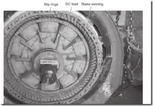
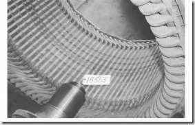
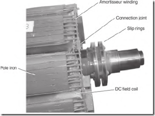
Synchronous motors are used on loads that need constant speed. These motors range in size from small to many thousands of horsepower. Figures 5.39 to 5.42 are various pictures of the synchronous motor and its components.
FIGURE 5.39 The synchronous motor. Smith Services.
FIGURE 5.40 Stator of a synchronous motor. Smith Services.
DC field coil pole iron FIGURE 5.41 Rotor of a synchronous motor. Smith Services.
FIGURE 5.42 Amortisseur winding (squirrel cage) embedded in the iron of the DC poles. Smith Services.
The synchronous motor doesn’t have good starting torque and must start with very little load. Common applications are refrigeration compressors and air compressors, because these units can be started with no load and then activated after the motor is up to speed.
The synchronous motor is often used to correct the power factor in industry.
Components of the Synchronous Motor
The synchronous motor has a three-phase stator and frame, as an induction motor or the wound rotor motor (described later) has. The stator winding is either wye or delta connected (or with multiple wyes or deltas) internally. They are usually connected one voltage. Most operate on high voltage (2400 volts and higher) and have form-wound coils (Fig. 5.40).
The rotor of the synchronous motor has DC field poles mounted on it (Fig.
5.41). There are as many poles on the rotor as there are in one phase of the stator. The DC coils get their power from two slip rings mounted on the shaft.
The DC field of the synchronous motor is similar to the shunt field of a DC motor. (The resistance of the coils limits the amperes.) The coils (mounted on the rotor) are well cooled.
The pole iron for the DC poles is laminated, like the stator poles. It’s fastened securely to a frame called a spider. The spider is mounted on the motor’s shaft.
Each pole has a squirrel cage winding embedded in it above the DC coils (Fig. 5.42). This is called the amortisseur winding. The bars in the pole iron have both ends connected to sections of an end ring. The end ring sections and bars stay with each pole iron piece when the rotor is disassembled. Additional end ring sections join the pole end ring sections to form a complete circuit. The ring sections are lapped and bolted together securely, both mechanically and electrically. Like any squirrel cage winding, the circuit has low voltage, and carries very high amperes when starting. When the DC field is energized and the rotor is at synchronous speed, there is no voltage or current


![clip_image002[5] clip_image002[5]](http://machineryequipmentonline.com/electric-equipment/wp-content/uploads/2017/04/clip_image0025_thumb1.jpg)
