BASIC STEADY-STATE EQUIVALENT CIRCUIT
When the IM is fed in the stator from a three-phase balanced power source, the three-phase currents produce a traveling field in the airgap. This field produces emfs both in the stator and in the rotor windings: E1 and E2s. A symmetrical cage in the rotor may be reduced to an equivalent three-phase winding.
The frequency of E2s is f2.
f11 −n p 1 = n1n−1 n n p1 1 = Sf1 (7.1) f2 = f1 −np1 = p
This is so because the stator mmf travels around the airgap with a speed n1 = f1/p1 while the rotor travels with a speed of n. Consequently, the relative speed of the mmf wave with respect to rotor conductors is (n1 – n) and thus the rotor frequency f2 in (7.1) is obtained.
Now the emf in the short-circuited rotor “acts upon” the rotor resistance Rr and leakage inductance Lrl:
E2s = SE2 = (Rr + jSω1Lrl )Ir (7.2)
ES2s = E2 = RSr + ωj 1Lrl Ir (7.3)
If Equation (7.2) includes variables at rotor frequency Sω1, with the rotor in motion, Equation (7.3) refers to a circuit at stator frequency ω1, that is with a “fictious” rotor at standstill.
Now after reducing E2, Ir, Rr,and Lrl to the stator by the procedure shown in Chapter 6, Equation (7.3) yields
E2‘= E1 = R ‘ R ‘r + r S1 −1 + ωj 1L ‘rl Ir ‘ (7.4)
E2 = Kw2W2 = K ; KE w2 =1, W2 =1/2 for cage rotors E1 Kw1W1
IIrr‘ = m Km K21 w2w1WW12 = K ; WI 2 =1/ 2, m2 = N for r cage rotors (7.5)
Rr = Lrl = KE (7.6) Rr’ Lrl’ KI
Kw1 = Kq1 ⋅Ky1; Kw2 = Kq2 ⋅Ky2 ⋅Kskew (7.7)
W1, W2 are turns per phase (or per current path)
Kw1, Kw2 are winding factors for the fundamental mmf waves
m1, m2 are the numbers of stator and rotor phases, Nr is the number of rotor slots The stator phase equation is easily written:
−E1 = Vs −Is(Rs + ωj 1Lsl ) (7.8) because in addition to the emf, there is only the stator resistance and leakage inductance voltage drop.
Finally, as there is current (mmf) in the rotor, the emf E1 is produced concurrently by the two mmfs (Is, Ir′).
E1 = − dψdt1m = − ωj 1L1m(Is + Ir ‘) (7.9)
If the rotor is not short-circuited, Equation (7.4) becomes
E1 − VSr ‘ = R ‘ R ‘r + r S1 −1 + ωj 1L ‘rl Ir ‘ (7.10)
The division of Vr (rotor applied voltage) by slip (S) comes into place as the derivation of (7.10) starts in (7.2) where
SE2 − Vr = (Rr + jSω1Lrl )Ir (7.11)
The rotor circuit is considered as a source, while the stator circuit is a sink. Now Equations (7.8) – (7.11) constitute the IM equations per phase reduced to the stator for the rotor circuit.
Notice that in these equations there is only one frequency, the stator frequency ω1, which means that they refer to an equivalent rotor at standstill, but with an additional “virtual” rotor resistance per phase Rr(1/S−1) dependent on slip (speed).
It is now evident that the active power in this additional resistance is in fact the electro-mechanical power of the actual motor
Pm = Te ⋅ π2 n = 3R ‘r S1 −1( )Ir ‘ 2 (7.12) with n = f1 (1−S) (7.13) p1
ωp1 Te = 3R ‘r S( )Ir ‘ 2 = Pelm (7.14)
1
Pelm is called the electromagnetic power, the active power which crosses the airgap, from stator to rotor for motoring and vice versa for generating. Equation (7.14) provides a definition of slip which is very useful for design purposes:
S = 3R ‘r ( )Ir ‘ 2 = PCor (7.15)
Pelm Pelm
Equation (7.15) signifies that, for a given electromagnetic power Pelm (or torque, for given frequency), the slip is proportional to rotor winding losses.
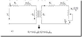
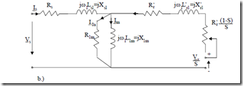
Figure 7.1 The equivalent circuit
Equations (7.8) – (7.11) lead progressively to the ideal equivalent circuit in Figure 7.1.
Still missing in Figure 7.1a are the parameters to account for core losses, additional losses (in the cores and windings due to harmonics), and the mechanical losses.
The additional losses Pad will be left out and considered separately in Chapter 11 as they amount, in general, to up to 3% of rated power in welldesigned IM.
The mechanical and fundamental core losses may be combined in a resistance R1m in parallel with X1m in Figure 7.1b, as at least core losses are produced by the main path flux (and magnetization current Im). R1m may also be combined as a resistance in series with X1m, for convenience in constant frequency IMs. For variable frequency IMs, however, the parallel resistance R1m varies only slightly with frequency as the power in it (mainly core losses) is proportional to E12 = ω12Kw12Φ12, which is consistent to eddy current core loss variation with frequency and flux squared.
R1m may be calculated in the design stage or may be found through standard measurements.
R1m = 3PEiron12 = 3XP1miron2Im2 ; Ioa << Im (7.16)
CLASSIFICATION OF OPERATION MODES
The electromagnetic (active) power crossing the airgap Pelm (7.14) is positive for S > 0 and negative for S < 0.
That is, for S < 0, the electromagnetic power flows from the rotor to the stator. After covering the stator losses, the rest of it is sent back to the power source. For ω1 > 0 (7.14) S < 0 means negative torque Te. Also, S < 0 means n > n1 = f1/p1. For S > 1 from the slip definition, S = (n1 – n)/n1, it means that either n < 0 and n1(f1) > 0 or n > 0 and n1(f1) < 0.
In both cases, as S > 1 (S > 0), the electromagnetic power Pelm > 0 and thus flows from the power source into the machine.
On the other hand, with n > 0, n1(ω1) < 0, the torque Te is negative; it is opposite to motion direction. That is braking. The same is true for n < 0 and n1(ω1) > 0. In this case, the machine absorbs electric power through the stator and mechanical power from the shaft and transforms them into heat in the rotor circuit total resistances.
Now for 0 < S < 1, Te > 0, 0 < n < n1, ω1 > 0, the IM is motoring as the torque acts along the direction of motion.
The above reasoning is summarized in Table 7.1.
Positive ω1(f1) means positive sequence-forward mmf traveling wave. For negative ω1(f1), a companion table for reverse motion may be obtained.
Table 7.1 Operation modes (f1/p1 > 0)
|
S |
– – – – |
0 |
+ + + + |
1 |
+ + + + |
|
n |
+ + + + |
f1/p1 |
+ + + + |
0 |
|
|
Te Pelm |
0 – – – – |
0 0 |
+ + + + + + + + |
+ + + + + + + + |
0 0 |
|
Operation mode |
Generator |
Motor |
Braking |

