When a conductor cuts or is cut by magnetic lines of force, a voltage is generated in it. The amount of voltage can be controlled by:
• The number of conductors in the armature
• The number of magnetic lines of force (or flux) from the stator
• The speed at which the armature conductors cut or are cut by the lines of force
The number of conductors is the same as the number of turns in the slot of an armature. Each turn of wire cuts lines of force and generates a given amount of voltage. The voltage generated in each turn is added to the next turn—this compares to flashlight batteries in series. The number of turns in the slots of the armature determines the basic voltage output of a generator.
The number of magnetic lines of force (being cut by the armature’s conductors) controls its voltage output value. As the number of lines of force increases, the voltage value also increases in the conductors. The number
of lines of force can be varied with a control that changes the number of amperes flowing in the stator fields. The output voltage will vary with the change in ampere flow through the stator fields. This control adjustment won’t make a large change in the voltage output of a generator.
The speed at which the conductors cut the lines of force is determined by the generator’s RPM. The recommended speed is on the generator’s nameplate. The voltage output value will change with the speed change.
The Shunt Generator
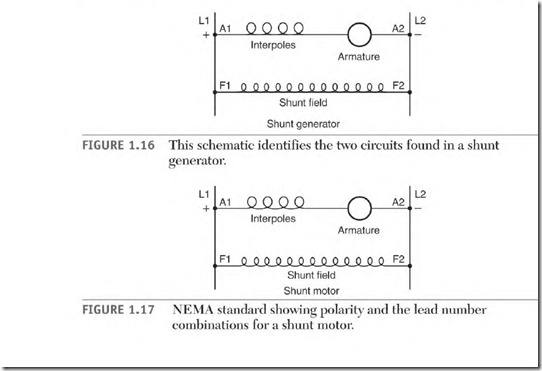
The shunt generator has two circuits (Fig. 1.16), the armature and interpoles
(Al and A2) and the shunt field (Fl and F2).
Figure 1.17 shows the NEMA (National Electrical Manufacturers Association) standard connection for counterclockwise rotation facing the end opposite the shaft.
The Armature and Interpoles
Armature leads are identified as Al and A2. The armature windings produce all of the generator’s power output. The number of turns of wire in the slots
of the armature determines its voltage output value. The ampere rating of the generator determines the armature winding’s wire size.
The armature circuitry consists of many coils that are connected to the commutator segments. The commutator segments control the direction of current flow in each coil of the armature. The basics of this
circuitry and a more detailed explanation are provided in the section, “Operation of a DC Motor. ‘![]()
Interpoles are poles strategically placed in the stator to decrease brush arcing. They will be covered in depth later in this chapter.
The Shunt Field
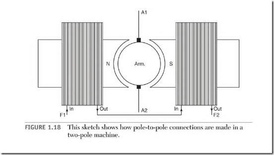
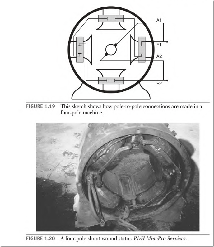
The shunt field (Fig. 1.18) consists of coils of wire and laminated iron. Each coil and its iron make a pole. Fig. 1.19 shows a four-pole sketch. The coils are connected so that each is the opposite polarity from the one next to it. The number of north poles always equals the number of south poles. Figure 1.20 shows a four-pole stator.
The purpose of a generator’s shunt field is to furnish magnetic lines of force (flux) for the armature conductors to cut. Power is produced as armature conductors cut the lines of force. The shunt field coils consist of hundreds of feet of wire. The total length of the wire in these coils controls the current. (Each wire size has a resistance value per 1000 feet.) The large quantity of wire in the shunt field circuit keeps its coils from overheating.


