Sound Mixer Architecture and Circuit Blocks
The largest, most expensive piece of capital electronic equipment in any professional studio is the main studio mixer. So much so that in publicity shots of a recording studio this component is always seen to dominate the proceedings! Perhaps that’s why there seem to be so many terms for it: mixer, mixing desk, or just desk, audio console, console, and simply “the board,” to name but a few. To many people outside of the recording industry, the audio mixer represents the very essence of sound recording. This is partially correct, for it is at the console that many of the important artistic decisions that go toward mixing a live band or a record are made. However, in engineering terms, this impression is misleading. The audio console is a complicated piece of equipment but, in its electronic essence, its duties are relatively simple. In other words, the designer of an audio mixer is more concerned with the optimization of relatively simple circuits, which may then be repeated many, many times, than he/she is with the design of clever or imaginative signal processing. But before we investigate the individual circuit elements of an audio mixer, it is important to understand the way in which these blocks fit together. This is usually termed system architecture.
System Architecture
There is no simple description of audio console system architecture. That’s because there exist different types of consoles for different duties and because every manufacturer (and there are very many of them) each has their own ideas about how best to configure the necessary features in a manner that is operationally versatile, ergonomic, and maintains the “cleanest” signal path from input to output. However, just as houses all come in different shapes and sizes and yet all are built relying upon the same underlying assumptions and principles, most audio mixers share certain system topologies.
Input Strip
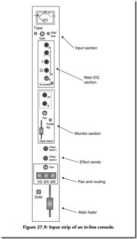
The most conspicuous “building block” in an audio console, and the most obviously striking at first glance, is the channel input strip. Each mixer channel has one of these and they tend to account for the majority of the panel space in a large console. A typical input strip for a small recording console is illustrated in Figure 27.9. When you consider that a large console may have 24, 32, or perhaps 48 channels—each a copy of the strip illustrated in Figure 27.9—it is not surprising that large commercial studio consoles look so imposing. But always remember, however “frightening” a console looks, it is usually only the sheer bulk that gives this impression. Most of the panel is repetition and once one channel strip is understood, so are all the others!
Much harder to fathom, when faced with an unfamiliar console, are the bus and routing arrangements that feed the group modules, the monitor, and master modules. These “hidden” features relate to the manner in which each input module may be assigned to the various summing amplifiers within the console. And herein lies the most important thing to realize about a professional audio console; that it is many mixers within one console. First let’s look at the groups.
Groups
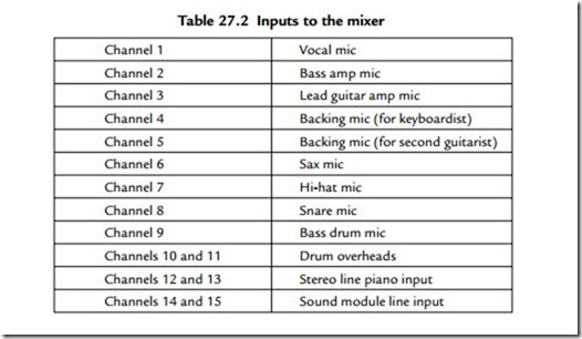
Consider mixing a live rock band. Assume that it is a quintet: a singing bass player, one guitarist, a keyboard player, a saxophonist, and a drummer. The inputs to the mixer might look something like this:
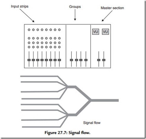
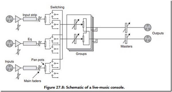
Clearly inputs 7 to 11 are all concerned with the drums. Once these channels have been set so as to give a good balance between each drum, it is obviously convenient to group these faders together so that the drums can be adjusted relative to the rest of the instruments. This is the role of the separate summing amplifiers in a live console, to group various instruments together. That’s why these smaller “mixers within mixers” are called groups. These group signals are themselves fed to the main stereo mixing amplifier, the master section. Mixer architecture signal flow is therefore channeled to groups and groups to master output mixer, as shown in Figure 27.7. A block schematic of a simplified live-music mixer is given in Figure 27.8 in which this topology is evident.
Pan Control
Stereophonic reproduction from loudspeakers requires that stereo information is carried by interchannel intensity differences alone, as there is no requirement for interchannel delay differences. The pan control progressively attenuates one channel while progressively strengthening the other as the knob is rotated, with the input being shared equally between both channels when the knob is in its center (12 o’clock) position. In the sound mixer shown in Figure 27.8, note that the channel pan control operates in a rather more flexible manner, as a control that may be used to “steer” the input signal between either of the pairs of buses selected by the routing switches. The flexibility of this approach becomes evident when a console is used in a multitrack recording session.
Effect Sends and Returns
Not all the functions required by the balance engineer can be incorporated within the audio mixer. To facilitate the interconnection with outboard equipment, most audio mixers have dedicated mix amplifiers and signal injection points called effect sends and returns, which make incorporation of other equipment within the signal flow as straightforward as possible.
The Groups Revisited
In a recording situation, the mixing groups may well ultimately be used in the same manner as described in relation to the live console, to group sections of the arrangement so as to make the task of mixing more manageable. But the groups are used in a totally different way during recording or tracking. During this phase, the groups are used to
route signals to the tracks of the multitrack tape machine. From an electronic point of view, the essential difference here is that, in a recording situation, the group outputs are utilized directly as signals and a recording mixer must provide access to these signals. Usually a multitrack machine is wired so that each group output feeds a separate track of the multitrack tape recorder. Often there are not enough groups to do this, in which case, each group feeds a number of tape machine inputs, usually either adjacent tracks or in “groups of groups” so that, for instance, groups 1 to 8 will feed inputs 1 to 8 and 9 to 16 and so on.
The Recording Console
So far, this is relatively straightforward. But a major complication arises during the tracking of multitrack recordings because not only must signals be routed to the tape recorder via the groups, tape returns must be routed back to the mixer to guide the musicians as to what to play next. And this must happen at the same time! In fact, it is just possible for a good sound engineer, using “crafty” routing, to cope with this using a straightforward live mixing desk. But it is very difficult. What is really required is a separate mixer to deal with the gradually increasing numbers of tape replay returns, thereby keeping the main mixer free for recording duties. Various mixer designers have solved this problem in different ways. Older consoles (particularly of English origin) have
tended to provide an entirely separate mixer (usually to the right of the group and main faders) devoted to dealing with the return signals. Such a mixer architecture is known as a split console. The alternative approach, which is now very widespread, is known as the in-line console, so named because the tape-return controls are embedded within each channel strip, in line with the main fader. This is the type of console considered in detail later. From an electronic point of view, very little difference exists between these approaches; the difference is more one of operational philosophy and ergonomics.
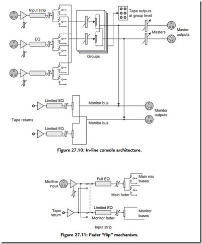
Both the split and in-line console are yet another example of a “mixer within a mixer.” In effect, in the in-line console, the tape returns feed an entirely separate mixer so that each tape return signal travels via a separate fader (sometimes linear, sometimes rotary) and pan control before being summed on an ancillary stereo mix bus known as the monitor bus. The channel input strip of an in-line console is illustrated in Figure 27.9. The monitor bus is exceptionally important in a recording console because it is the output of this stereo mix amplifier that supplies the signal that is fed to the control room power amplifier during the tracking phase of the recording process. (Usually, control room outputs are explicitly provided on the rear panels of a recording console for this purpose.) The architecture is illustrated in Figure 27.10. During mixdown, the engineer will want to operate using the main faders and pan controls, because these are the most operationally convenient controls, being closest to the mixer edge nearest the operator. To this end, the in-line console includes the ability to switch the tape returns back through the main input strip signal path, an operation known as “flipping” the faders. The circuitry for this is illustrated in Figure 27.11.
Talkback
Talkback exists so that people in the control room are able to communicate with performers in the studio. So as to avoid sound “spill” from the loudspeaker into open microphones (as well as to minimize the risk of howl-round), performers inside the studio invariably wear headphones and therefore need a devoted signal that may be amplified and fed to special headphone amplifiers. In the majority of instances this signal is identical to the signal required in the control room during recording (i.e., the monitor bus). In addition, a microphone amplifier is usually provided within the desk, which is summed with the monitor bus signal and fed to the studio headphone amplifiers. This microphone amplifier is usually energized by a momentary switch to allow the producer or engineer to communicate with the singer or instrumentalist, but which cannot, thereby, be left open, thus distracting the singer or allowing them to hear a comment in the control room that may do nothing for their ego!
Equalizers
For a variety of reasons, signals arriving at the recording console may require spectral modification. Sometimes this is due to the effect of inappropriate microphone choice or of incorrect microphone position. Sometimes it is due to an unfortunate instrumental tone (perhaps an unpleasant resonance). Most often, the equalizer (or simply EQ) is used in a creative fashion to enhance or subdue a band (or bands) of frequencies so as to blend an instrument into the overall mix or boost a particular element so that its contribution is more incisive.
It is this creative element in the employment of equalization that has created the situation that exists today, that the quality of the EQ is often a determining factor in a recording engineer’s choice of one console over another. The engineering challenges of flexible routing, low interchannel cross talk, low noise, and good headroom having been solved by most good manufacturers, the unique quality of each sound desk often resides in the equalizer design.
Unfortunately, this state of affairs introduces a subjective (even individualistic) element into the subject of equalization, which renders it very difficult to cover comprehensively. Sometimes it seems that every circuit designer, sound engineer, and producer each has his, or her, idea as to what comprises an acceptable, an average, and an excellent equalizer! A simple equalizer section—and each control’s effect—is illustrated in Figure 27.12.
