THE ABRIDGED PSYCHROMETRIC CHART
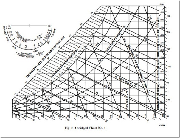
Figure 2 is an abridged form of Chart No. 1. Some of the scale lines have been removed to simplify illustrations of the psychrometric processes. Smaller charts are used in most of the subsequent examples. Data in the examples is taken from full-scale charts The major lines and scales on the abridged psychrometric chart identified in bold letters are:
— Dry-bulb temperature lines
— Wet-bulb temperature lines
— Enthalpy or total heat lines
— Relative humidity lines
— Humidity ratio or moisture content lines
— Saturation temperature or dew point scale
— Volume lines in cubic feet per pound of dry air
The chart also contains a protractor nomograph with the following scales:
— Enthalpy/humidity ratio scale
— Sensible heat/total heat ratio scale
When lines are drawn on the chart indicating changes in psychrometric conditions, they are called process lines.
With the exception of relative humidity, all lines are straight. Wet-bulb lines and enthalpy (total heat) lines are not exactly the same so care must be taken to follow the correct line. The dry-bulb lines are not necessarily parallel to each other and incline slightly from the vertical position. The purpose of the two enthalpy scales (one on the protractor and one on the chart) is to provide reference points when drawing an enthalpy (total
heat) line. The protractor nomograph, in the upper left corner, is used to establish the slope of a process line. The mechanics of constructing this line are discussed in more detail in the STEAM JET HUMIDIFIERS section.
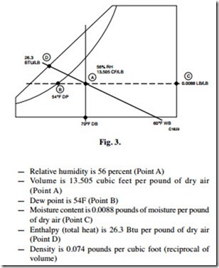
The various properties of air can be determined from the chart whenever the lines of any two values cross even though all properties may not be of interest. For example, from the point where the 70F dry-bulb and 60F wet-bulb lines cross (Fig. 3, Point A), the following additional values can be determined:
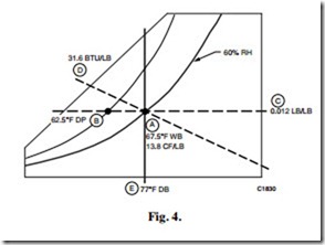
Figure 4 is another plotting example. This time the dry-bulb temperature line and relative humidity line are used to establish the point. With the relative humidity equal to 60 percent and the dry-bulb temperature at 77F (Fig. 4, Point A), the following values can be read:
— Wet-bulb temperature is 67.5F (Point A)
— Volume is 13.8 cubic feet per pound of dry air (Point A)
— Dew point is 62.5F (Point B)
— Moisture content is 0.012 pounds of moisture per pound of dry air (Point C)
— Enthalpy is 31.6 Btu per pound of dry air (Point D)
— Density is 0.0725 pounds per cubic foot (reciprocal of volume)
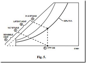
Figure 5 is the same as Figure 4 but is used to obtain latent heat and sensible heat values. Figures 4 and 5 indicate that the enthalpy (total heat) of the air is 31.6 Btu per pound of dry air (Point D). Enthalpy is the sum of sensible and latent heat (Line A to E + Line E to D, Fig. 5). The following process determines how much is sensible heat and how much is latent heat. The bottom horizontal line of the chart represents zero moisture content. Project a constant enthalpy line to the enthalpy scale (from Point C to Point E). Point E enthalpy represents sensible heat of 18.7 Btu per pound of dry air. The difference between this enthalpy reading and the original enthalpy reading is latent heat. In this example 31.6 minus 18.7 equals 12.9 Btu per pound of dry air of latent heat. When the moisture content of the air changes but the dry-bulb temperature remains constant, latent heat is added or subtracted.


