Converting the Program
Developing a program for a programmable logic controller is a little different than designing a circuit with relay logic. There are several rules that must be not physically exist. Any number of contacts can be assigned to this relay and they can be open or closed.
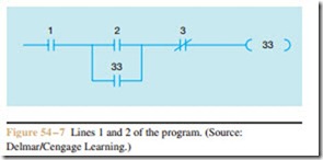
The #33 contact connected in parallel with input #2 is the holding contact, labeled CR-1 in Figure 54 – 2.
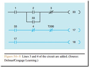
The next two lines of logic are shown in Figure 54 – 8. The third line of logic in the schematic in Figure 54 – 2 contains a normally open CR-2 contact, a normally closed float switch contact, a normally closed on- delay timed contact and solenoid coil A. The fourth line of logic contains solenoid coil B connected in parallel with solenoid coil A. Line 3 in Figure 54 – 8 uses a normally open contact, assigned the number 33 for contact CR-2. A normally closed contact symbol is assigned the number 4. Since the float switch is connected to input #4, it will control the action of this contact. As long as input #4 remains in a low state, the contact will remain closed. If the float switch should close, input #4 will be- come high and the number 4 contact will open. The next contact is timed contact TR-1. The chart in Figure 54 – 6 indicates that timers and counters are assigned numbers 200 through 264. In this circuit, timer TR will be as- signed #200. Line 3 ends with coil #17. When coil 17 becomes energized, it will turn on output 17 and con- nect solenoid coil A to the line.
The schematic in Figure 54 – 2 shows that solenoid coil B is connected in parallel with solenoid coil A. Programmable logic controllers do not permit coils to be connected in parallel. Each line of logic must end with its own coil. Since solenoid coil B is connected in parallel with A, they both operate at the same time. This logic can be accomplished by assigning an inter- nal contact the same number as the coil controlling output 17. Notice in Figure 54 – 8 that when coil 17 energizes it will cause contact 17 to close and energize output 18 at the same time.
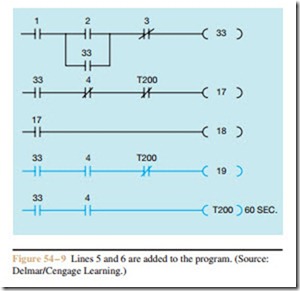
In Figure 54 – 9, lines 5 and 6 of the schematic are added to the program. A normally open contact as- signed number 33 is used as contact CR-3. A normally open contact assigned the number 4 is controlled by the float switch, and a second normally closed timed con- tact controlled by timer 200 is programmed in line 5. The output coil is assigned the number 19. When this coil energizes, it turns on output 19 and connects motor starter coil M to the line.
Line 6 contains timer coil TR. Notice in Figure 54 – 2 that coil TR is connected in parallel with contact TR-2 and coil M. As was the case with solenoid coils A and B, coil TR cannot be connected in parallel with coil M. According to the schematic in Figure 54 – 2, coil TR is actually controlled by contacts CR-3 and the normally open float switch. This logic can be accomplished as shown in Figure 54 – 9 by connecting coil T200 in series with contacts assigned the numbers 33 and 4. float switches do not normally contain this many contacts, but since the physical float switch is supply- ing a high or low voltage to input 4, any number of con- tacts assigned the number 4 can be used.
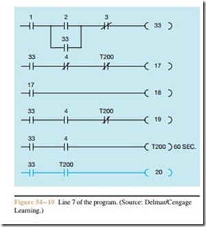
The last line of the program is shown in Figure 54 – 10. A normally open contact assigned the number 33 is used for contact CR-4, and a normally open contact controlled by timer T200 is used for the nor- mally open timed contact labeled TR-3. Coil 20 controls the operation of solenoid coil C.
The circuit shown in Figure 54 – 2 has not been converted to a program that can be loaded into a pro-
grammable logic controller. The process is relatively simple if the rules concerning PLCs are followed.


