Rotation
There are very few machines that do not include a rotating shaft at some place, and the sensing and measurement of rotational movement is therefore important. The quantities that are used to measure rotation correspond to the quantities that are used in the measurement of linear motion in such a way that the same types of equations can be used, substituting the rotational quantities for the linear ones. The quantity that corresponds
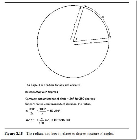
to distance for a rotation is the angle rotated. For a complete rotation of a shaft, this angle is 360o, and so, in terms of degrees, the total angle turned by a shaft is 360 x the number of complete turns. The degree, however, is an artificial unit that is not used in calculations, and most textbooks show the relationships between rotational quantities in terms of radians. The definition of the radian is illustrated in Figure 2.18, and it leads to the angle for one complete rotation being 27r radians. To convert from degrees to radians, divide the angle in degrees by 57.3; to convert from radians to degrees, multiply by 57.3.
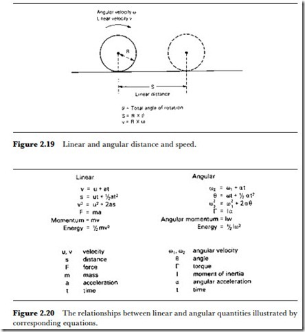
Because angle in rotational motion corresponds to distance in linear motion, rotational speed is defined as the angle through which a shaft turns per second, and corresponds to linear speed. If the rotating object is a wheel and is in contact with a surface, then Figure 2.19 shows how the linear distance and velocity are related to the angle turned and the angular velocity. The angular acceleration is defined as the rate of change of angular velocity, and the equations that relate these angular quantities, along with the linear counterparts, are illustrated in Figure 2.20. The sensors for angular motion are also very closely related to those that are used for linear motion.
Taking angular velocity first, the simplest form of sensor, which can also act as a transducer, is the AC or DC generator. For sensing and measurement purposes only a minimum of power must be used, so that a miniature AC generator called the tacho-generator is normally used. The construction
of the tacho-generator, usually abbreviated to tacho, is a more precision- built version of an AC generator and usually has rotating magnets with output from stator coils so as to avoid the need for slip-rings. The frequency of the output signal is proportional to the revolutions per second of the shaft that is coupled to the tacho, so that a frequency-sensitive detector can be used to give a DC output proportional to angular frequency. The tacho can be used over a wide range of angular velocity values, and if the frequency detector is reasonably linear then the readings can be of high precision. The drawback for some applications is the need to make a mechanical coupling between the tacho and the revolving shaft.
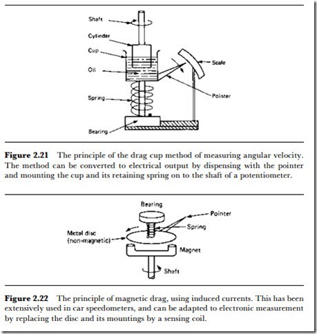
Another form of measurement depends on ‘drag systems’. A drag system involves a frictional coupling between the rotating shaft and some object that is restrained and whose displacement can be measured. One version of this is the drag cup, whose principle is illustrated in Figure 2.21. The end of the vertical rotating shaft dips into oil contained in a cup, and the cup is
held in a spring mounting so that its rotation can be measured by any type of sensor, which can be a potentiometer, capacitor system, rotary LVDT or digital encoder (see later). The motion of the shaft is communicated by the viscosity of the oil to a turning force (torque) on the cup, and the dis- placement of the cup against the spring is measured by the sensor. Since dis- placement should be proportional to torque, which in turn should be proportional to rotational speed of the shaft, output from the sensor is pro- portional to rotational speed over a small range of speeds. The range is small because the assumption that torque is proportional to rotational speed holds good for only a small range of speeds, and the system is best suited for slow rotations.
Another version of this method that is much more versatile is the magnetic disc type. A magnet on the end of the shaft will cause a rotating
field as the shaft turns, and if a metal disc (which need not be magnetic) is held close to this magnet (Figure 2.22) then the torque on the disc (caused by the interaction of the magnet and the eddy currents that are induced in the disc) will be proportional to the angular speed of the shaft. This is the scheme that has been used for many years for car speedometer heads, and it operates best at a medium range of angular speeds. One particular advantage is that no contact is needed, though there must not be any metal between the magnet and the disc.
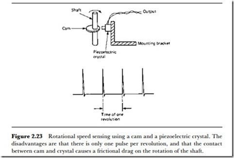
For some purposes, a signal that is sent out for each revolution of a wheel or shaft is sufficient for angular velocity sensing, and this can be achieved by the use of piezoelectric or magnetic pulsing. A piezoelectric pulse can be operated, as indicated in Figure 2.23, by a cam on a shaft that will cause the piezoelectric crystal to be compressed on each rotation of the shaft. Since the signal from the piezoelectric crystal can be of several volts amplitude, this type of sensor often needs no amplification, but the output
is at a high impedance. In addition, the friction on the shaft is fairly large compared to the alternative system of magnetic pulsing. The magnetic pulse system uses a permanent magnet mounted on a wheel or shaft and passing over a coil at one part of the revolution. As the magnet moves, a voltage is induced in the coil, so providing a signal for each revolution. The magnetic pulse system is not ideal if the rotation is slow, because the amplitude of the pulse is affected by the rotational speed, and there must not be any magnetic metal between the magnet and the coil.
Angular displacement measurement methods fall into two groups: those for very small angular displacements that are temporary, and those for large displacements. Temporary small displacements are of a degree or less, and the shaft or other rotating object returns to its original position following the rotation. Such small displacements are sensed by variants of the methods used for small linear displacements, such as capacitive, strain gauge and piezo sensors.
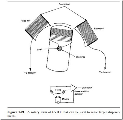
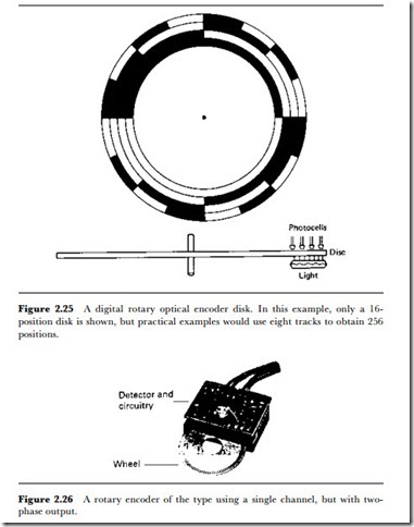
For larger displacements, inductive (particularly LVDT) methods are useful, and Figure 2.24 shows a typical method. Potentiometric methods are also useful, but if the normal type of potentiometer construction is used, the angle of rotation is restricted to about 270o. The rotary digital encoder can be used to provide a direct digital output, using a wheel of the form shown in Figure 2.25 that has transparent and opaque sectors drawn in a pattern that provides as many channels of digital bits as will be needed for the required resolution.
The digital encoder can also be used to measure angular velocity and acceleration, and this makes it particularly useful for a very wide range of
applications, assuming that suitable equipment is available to obtain the velocity and acceleration values from the angular position digital codes. This usually implies input to a computer that can run suitable software. If digital methods cannot be used, the changing output from another type of angular velocity measurement can be differentiated by means of an analogue computer stage using an operational amplifier.
In practice, optical encoders often use methods that are closer to
analogue than to strictly binary digital methods, employing a disk on which the sectors are equally spaced (Figure 2.26). Such encoders can be obtained in the open form, allowing the disk to be attached to any rotating object, or as sealed units with a shaft that must be coupled to the rotating object. The number of output pulses per revolution is typically 1000-2500, depending on the type, and the signal levels are arranged to be suitable for digital TTL circuits, with a low level at a maximum voltage of 0.4 V and a high level with a minimum of 2.4 V. Maximum permissible disk speeds for the larger enclosed types range from 2400 rpm for the high-resolution disks
to 6000 rpm for the lower resolution types, corresponding to a maximum operating frequency of 100 kHz. Miniature varieties can be used up to speeds of 30 000 rpm, and the unenclosed disks can typically be used up to 12 000 rpm.
The outputs of these optical encoders are not as a set of binary channels, but as two-phase signals, with the phase angle maintained at 90o.
Although the signals are square-waves at the lower speeds of rotation, they become approximately sinusoidal at higher speeds. In addition to the phase signals, a synchronization signal is available which allows a phase- sensitive detector to find the direction of rotation.
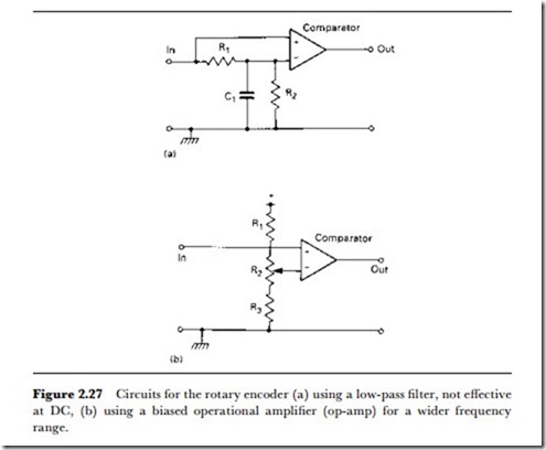
For the simplest applications in sensing shaft speed, either of the phase outputs can be fed into a comparator, Figure 2.27(a), with the AC signal fed to the positive input and the DC component (because of the low-pass filter) to the negative input. This circuit is applicable only to rotational speeds for which the frequency is high enough to allow the filter to be effective, and for response to zero frequency the circuit of Figure 2.27(b) is better, using a potentiometer to set the input level at the negative input of the operational amplifier to a level midway between the signal peaks. A counter can be connected to the output of the comparator in either case.
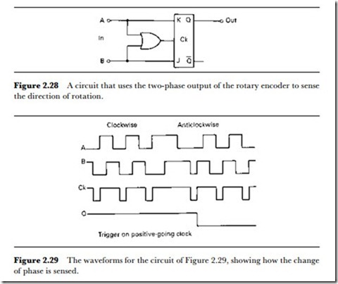
Vhere the direction of rotation must be sensed, the phase differences can be used in a circuit such as that of Figure 2.28, in which the output from a J-K flip-flop is used to indicate direction (other circuits being used to indicate speed). In this circuit, the OR gate (which can be made using two NOR gates) forms a clock input to the J-K flip-flop, and the A and B inputs from the encoder are each taken by way of a comparator to square the signals to an acceptable degree.
The waveforms for this circuit (Figure 2.29) show the action. The J-K flip-flop in this case is one that triggers on the positive-going edge of the clock, making use of the voltage levels at the J and K inputs just prior to triggering. Vhen the rotation is clockwise, the A signal is high and the B signal low just before the rising edge of the clock pulse (the delay in the OR gate will ensure that the clock is slightly delayed with respect to the signals at J or K), and this makes the Q output high. For anticlockwise rotation, the clock occurs when A is low and B is high, reversing the output of the flip-flop.
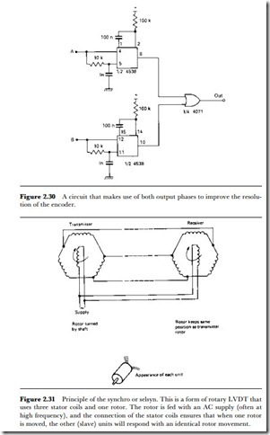
The resolution of an encoder which can produce as little as 100 pulses per second can be considerably improved by making use of the two-phase output, and a precision of 1o or better is possible by using a dual monostable in the circuit of Figure 2.30.
One particularly useful sensor for angular displacement is the synchro, also known as the seLsyn. This makes use of inductive principles, and a simple synchro system is illustrated diagrammatically in Figure 2.31. The aim is to sense an angular displacement, convert it to phase changes in electrical signals, and reproduce the same angular displacement at a receiver. As the diagram shows, a rotor is fed with an AC signal, typically a 1 kHz sine wave. The rotor is encased by a three-phase stator, with the coils equally
spaced so as to make the induced voltages at 120o to each other. The coils of this transmitter synchro are connected to the corresponding stator coils of a receiver synchro, whose rotor is fed with AC whose phase is locked to the phase of the AC used for the transmitter.
Any movement of the rotor of the transmitter synchro will cause a change in the amplitudes and phases of the voltages induced in the stator coils of the transmitter, and these same voltages and phases will exist across the receiver coils. The effect will be to cause a rotational force on the rotor of the receiver that will not reach zero until the rotor is at the same angular position relative to its stator coils as exists in the transmitter.
The device can have very low friction, and because the transmission is electrical, and because each unit is fed from a mains supply, the sensitivity can be high and the amount of torque fairly large. The device is used for diverse purposes, such as to transmit the angular position of a radar aerial, the direction of a wind vane, or the reading of a compass. The use of a synchro transmitter connected to a rotating radar aerial along with three- phase coils used for deflecting a cathode ray tube beam (with no rotor coil) was the main method of implementing the PPI (plan position indicator) type of radar for many years.
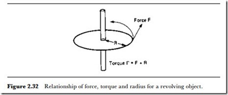
Finally, the most difficult of the rotational quantities to measure is torque, the rotational equivalent of force. As Figure 2.32 shows, torque can be obtained by using measurements of force or of angular acceleration. For static torque used, for example, to determine to what extent a nut or a bolt has been tightened, simple torque wrenches depend on a spring balance whose scale has been calibrated in terms of torque. Other static torque systems make use of a similar type of force measurement, using a strain gauge mounted on a shaft so as to measure strain in the direction of the circumference of the shaft. This is often the most practical arrangement for analogue measurements, since strain is proportional to stress caused by force. For a digital system, the use of an angular digital encoder and computer allows torque readings to be calculated.
Torque measurement on rotating shafts, as distinct from static measurement, is much more difficult. The conventional method of measuring torque on the shaft of a rotating motor uses a load with frictional coupling that can be adjusted so that the load remains still, but exerts torque on strain gauges. The measurement reliability can be improved by digitally processing the signals, but the method is not really useful for transient torque changes.
A more modern approach does not use mechanical coupling, and depends on the measurement of stator currents and voltages in an electric motor. The associated circuitry then computes the torque values, allowing for fast changes to be measured.
In addition to position, direction, distance and motion of an object, it may be necessary to sense the near presence of an object. This requires proximity detection, and the topic is discussed in Chapter 6.
