The Systems versus Components View of Electronics
A Fresh New Way to Learn about Electronics
In this Chapter:
● Systems defined.
● Examples of systems.
● Introduction to basic electronic components.
INTRODUCTION
When learning about electronics in the past, you started with basics of physics and math, and then went on to learn electrical theories. Next came instruction in how electronic components work, and then you combined them into circuits. Then you put the circuits together into specific pieces of equipment. Finally, at last, knowing the equipment, you could understand the application, such as TV or computers or audio or home system control or whatever. This approach to learning is called the bottom-up approach. You learned the details and added them all together to get to what you really wanted to know about—the applica- tion and its technology.
That is still the way you learn electronics in college today, and it is the approach taken by most other electronics books you may have seen. This book doesn’t take that old legacy path. Instead it skips most of the early background and theory, goes right for details on the circuits, and then builds to the applica- tions. It is a much more interesting way to learn electronics. And it is also far more relevant to how electronic equipment is implemented today. We call this way of learning the “systems view” of electronics.
WHY SYSTEMS AND NOT CIRCUITS?
What is the advantage of this approach? First, thanks to modern semiconductor technology, most electronic components and circuits are inside chips or inte- grated circuits (ICs). You can’t see them, and you can’t access, test, or replace
them. About all you can do is learn what they do, and then work with the vari- ous input and output signals. Since you do not have access to the components and circuits, there is some argument as to why you need to learn all that circuit theory detail. If you are an engineer designing ICs, you definitely need to know this. Otherwise, it is just a waste of time unless you want to know just for the heck of it. Some of it is nice to know, of course, but in most cases it is not nec- essary. What you really need to know is what the circuit is, what it does, what its characteristics are, and what the inputs and outputs should look like.
A good example is the power supply in a PC. If it goes bad, you just replace it with a $30 unit that you can buy online. Troubleshooting the power supply would take many hours and require some expensive test equipment and access to spare parts. The whole repair could take hours and at a typical rate of, say, $50/hour, or more, it could cost hundreds of dollars and take weeks to get the new parts. A quick replacement with the $30 unit takes only about a half hour at most. So for less time and money, you get your PC working faster. Not a bad deal at all.
A cell phone is the same. It takes hours of troubleshooting and very expen- sive test equipment to troubleshoot and repair one. A typical repair would cost hundreds of dollars. Consequently, it is rarely done. It is cheaper to get a new cell phone, and it will be a better one at that. And it may even be free if you renew your service contract. That’s electronics today.
The ability to analyze circuit operation by tracing electron flow through the various components used to be necessary. That made it necessary to know about all the components in detail and how they all come together to make a circuit. But with the systems view, you rarely need this knowledge unless you are an engineer designing the circuits or the equipment. In most cases you are not, so why invest the time?
The systems view is a better approach, as you do learn about the circuits and the equipment at a higher level. Later, if you want or need to, you can delve deeper into the circuit and component details, just for fun or to satisfy your curiosity. We won’t do that in this book. But you will get the system view and big picture that will serve you well in learning electronics.
The systems view is more important today because ICs have made it possi- ble to largely ignore the internal details. The ICs and systems on a chip (SoC) have resulted in the throw-away electronics society in which we live. It is no longer possible or economical to repair most electronic equipment thanks to ICs. The cost of labor, the cost of test instruments to troubleshoot equipment, and the difficulty of replacing ICs has made it more practical to just discard a bad piece of electronic equipment rather than repair it. It costs less and you get a newer and better replacement product as a result. Not a bad deal.
Yes, it is still possible to repair some equipment. For example, big expen- sive equipment such as a magnetic resonance imaging (MRI) machine is usually repairable, but it is done by replacing not bad components, but by replacing defective modules, subassemblies, or printed circuit boards.
You don’t have to know how to analyze circuits to do that. You just trouble- shoot by observing signal flow, measuring inputs and outputs, and replacing any module or subassembly that does not work. You get the equipment work- ing sooner and at lower cost.
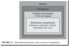
A good way to picture the systems view is shown in Figure 3.1. It all begins with the components that make up the circuits that in turn make up the modules and subassemblies, usually on printed circuit boards (PCBs). Those are put together to form pieces of equipment. Finally, multiple pieces of equip- ment may end up being interconnected to form some kind of system. A few system examples will show you the idea.
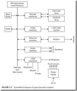
A personal computer (PC) is a great example of a system (see Figure 3.2). It is made up of modules including a mother board with its processor, mem- ory ICs, and input/output (I/O) interfaces. There is a power supply module, a hard disk drive, a CD/DVD drive, and perhaps a video card. Then the system is completed when it is connected to the video monitor, keyboard, printer, and Internet modem.
A consumer home entertainment system is made up of a big screen HDTV set, a cable or satellite box, a DVD/Blu-ray player, and an audio amplifier/ receiver with speakers. Other equipment may be involved. The TV itself or any of the other components are systems in their own right.
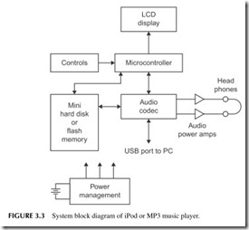
An iPod or MP3 player is a simple system. Shown in Figure 3.3, it consists of a memory, either a tiny hard disk drive or a solid-state flash memory that stores the music, an audio codec IC that does the digital music decompres- sion, digital-to-analog conversion and analog-to-digital conversion for storing music, a microcontroller that controls the whole thing including the selection controls, and the LCD readout. A pair of audio amplifiers and a headset com- plete the system. A power management system charges the battery and doles out DC to power the various ICs.
An MRI machine is a whole system. It is made up of the central bed sur- rounded by a superconducting magnet and radio frequency–sensing coils, high-power radio frequency (RF) amplifiers and detectors, the video imaging section, and a computer that runs the whole thing.
Anyway, you get the picture. There are big systems, little systems, and lots of in-between systems. Their main characteristic today is that you cannot get at the individual components and circuits, but there are exceptions.
In this book we look mainly at the circuits, equipment, and systems, not the components. We will give you a quickie introduction to the main components but move on to the circuits and systems.
ELECTRONIC COMPONENTS
Most systems today are collections of ICs wired together on printed cir- cuit boards and packaged in a housing of some sort. The MP3 player/iPod in Figure 3.3 is a great example. Each block in that diagram is an IC. In the past, systems were made with PCBs and other assemblies, but the circuits were made with discrete components, individual resistors, capacitors, diodes, transistors, and even some ICs. You will still see these here and there in modern equip- ment; just remember that most circuits and equipment are just a batch of ICs.
Just so you won’t be ignorant of components, here is a nutshell introduc- tion that should serve you well when learning electronics the system way. If you want to dig deeper, you can find many other books that will make your eyes glaze over with detail.
Switches
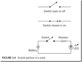
There is no simpler electrical component than a switch. It is just two (sometimes more) metal contacts and a mechanical device to open and close them. In one position the switch contacts are open and not touching so that no current will flow through them; the switch is “off.” Moving the switch lever, the contacts are made to touch making a path for current to flow; the switch is said to be “on.”
Figure 3.4 shows a switch in a circuit diagram called a schematic. This shows the switch connected to a battery and a light-emitting diode (LED) in a simple flashlight. The other component is a resistor to limit the current.
Resistors
Resistors are one of the most common components in electronics. These devices offer opposition to current flow; they limit or set the level of current in a circuit. The opposition to current flow is measured in ohms. The higher the ohms value, the more resistance it offers to electron flow.
Ohm’s Law
There is one key electrical relationship you should know, called Ohm’s law. It is simple and easy to understand. It says: The current in a circuit (I) is directly proportional to the voltage (V) and inversely to the resistance (R). It is usually expressed as a simple formula:
I = V/R
If you increase the voltage in a given resistance, the current increases. That makes sense since the voltage charge simply attracts and repels more electrons. Increasing the resistance makes the current decrease. Since resistance opposes current flow, more resistance with the same voltage will make the current decrease.
Keep this simple relationship in mind, as it is the heart of every electrical and electronic application.
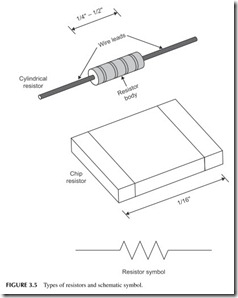
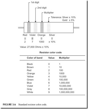
Today most resistors are made along with all the other circuitry in an IC. But discrete component resistors are also still fairly widely used. The most common ones are called chip resistors and look something like the one shown in Figure 3.5. They are small and you can just make them out when looking at a printed circuit board. Older but still used resistors are cylindrical like the one shown in Figure 3.5. The schematic symbol used to represent a resistor in a schematic diagram is shown in Figure 3.5. Color-coded resistors use a set of color bands with a special code to indicate their value (see Figure 3.6).
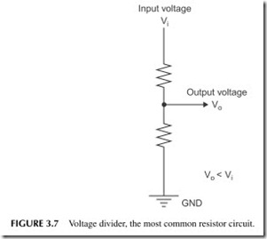
An example of a common resistor circuit is the voltage divider shown in Figure 3.7. It is used to attenuate a voltage or signal or make it lower. The two resistors of the voltage divider are connected in series. When current flows, a
voltage develops across the two resistors. The input voltage is divided between the two resistors according to their value. In any case, the output is taken from one of the resistors and it is lower in value than the input.
Capacitors
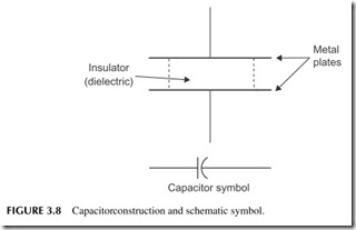
A capacitor is a device that stores an electrical charge. It is made up of two metallic plates separated by an insulator such as plastic or ceramic or even air (see Figure 3.8). The symbol for a capacitor in schematics is also shown.
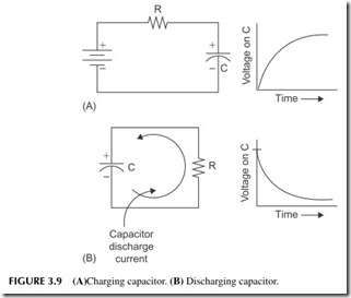
The basic function of a capacitor is to be charged or discharged. You charge the capacitor by applying a voltage to it as shown in Figure 3.9A. The electrons pile
up on one plate making it negative and are pulled away from the other plate mak- ing it positive. It takes a finite amount of time for the capacitor to charge as deter- mined by the values of capacitance (C), stated in farads (F), and resistance (R). That time is called the time constant (T). In the charged state, the capacitor stores the voltage. The capacitor in its charged state is almost like a battery, as it can sup- ply DC voltage to a circuit or load.
The energy stored in the capacitor is used by discharging it into a load such as a resistor (see Figure 3.9B). The electrons then flow from the negative plate through the resistor to the positive plate. Current flows until the charge is dis- sipated. Again, it takes time for the discharge to occur.
When capacitors are used with AC signals, they offer opposition to current flow called capacitive reactance. It is like resistance in that it determines cur- rent flow, but it varies with the frequency of the AC and capacitor value.
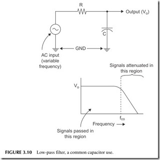
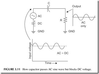
Capacitors perform all sorts of functions in electronic circuits. They are used for filtering and they are used to pass AC but block DC. Figure 3.10 shows a low-pass filter comprised of a resistor and a capacitor. This is a frequency-sensitive circuit that passes AC signals below a specific frequency called the cut-off frequency (fco) and attenuates the frequencies above the cut- off. Figure 3.11 shows how a capacitor passes AC but blocks DC.
A Word about Ground
In schematic diagrams like Figure 3.10, you will see the triangular-shaped symbol labeled GND. This means ground. Ground is an electronic term that refers to a common connecting point. It may be a common wire, a metal chassis, a copper area on a printed circuit board, or some other conductive part or area. In this fig- ure, it means that the bottom of the AC generator and the bottom of the capacitor are connected together.
Ground is also the common reference point for measuring all voltages.
Inductors
Inductors are mainly just coils of wire. When current flows through them, they produce a magnetic field and induce a voltage in themselves. This is called self- induction. The induced voltage has an opposite polarity of the applied voltage. The result is that the induced voltage causes opposition to the current flow. We often use that characteristic to control current flow in AC circuits. Like the capac- itor, the inductor is an opposition to AC called inductive reactance. Figure 3.12 shows the symbol of an inductor as used in schematic diagrams.
Transformers
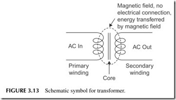
A transformer is usually comprised of two coils or windings on a common core. The schematic symbol is shown in Figure 3.13. A voltage applied to one winding called the primary causes current to flow and a magnetic field to develop. This magnetic field spreads out and induces voltage in the other
winding called the secondary, thereby transferring electrical energy for one coil to another by way of the magnetic field. Transformers are used to step up or step down voltage levels of AC signals. They are also used for signal isola- tion as well as impedance matching.
Diodes
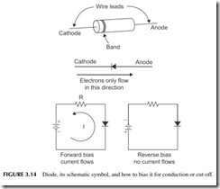
A diode is a semiconductor component that lets current flow through it in one direction but blocks current in the other direction depending on the polarity of the voltage applied to it. It acts like a polarity-sensitive switch. Figure 3.14 shows a typical diode, the diode schematic symbol, and how it is biased for current or no current.
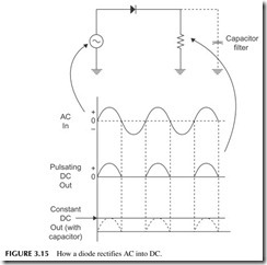
Diodes are used mainly for rectification, the process of converting AC into DC. Figure 3.15 shows how a diode converts an AC sine wave into DC pulses. If you put a capacitor across the load resistor, it will charge up to the peak sine voltage and store it. The result is that the output is a near-constant DC value. Most electronic power supplies work like this.
Special diodes are made to emit light (LED), regulate voltage (zener diode), act as a variable capacitor (varactor), or perform as a switch (PIN diode).
Transistors
A transistor is a three-terminal semiconductor device that uses a small input signal to control a much larger output signal. One type of transistor is the bipo- lar junction transistor (BJT) shown in Figure 3.16 . A small current applied to the base element is used to control a larger current flowing from emitter to collector.
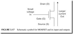
Another type of transistor is the metal oxide semiconductor-field-effect transistor (MOSFET). It too has three elements, as shown in Figure 3.17. A small voltage on the gate controls a larger current flowing from source to drain.
Transistors have two basic functions: amplification and switching. In ampli- fication, the small input variation causes larger output current variation. The small input signal isn’t really made bigger, but the larger output variation has the same shape and characteristics, resulting in the same effect. The transistor simply varies the larger DC current from the supply and shapes it like the input.
Amplifiers
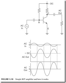
Figure 3.18 shows a simple BJT amplifier. The base resistor sets the base current turning the transistor on so that current flows from emitter to collec- tor. Its output voltage is a DC value at about half the supply voltage. Now, if a small AC signal is applied through the capacitor as shown, the base current will vary. This will vary the collector current and the voltage across the col- lector resistor. A small variation in the base current produces a larger variation in the collector current. The output voltage is an enlarged version of the input, except that it is reversed in phase. We say that the output is 180 degrees out of phase with the input, called phase inversion. The output is a DC signal, but to convert it to AC we pass it through a capacitor to the load. All amplifiers gen- erally work like this.
Switches
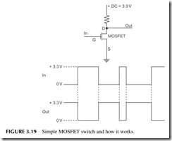
As a switch, the transistor output current is turned off or on by the smaller input current or voltage. A small input signal can switch a larger output cur- rent off and on. Switching transistors can switch very fast (in less than nano- seconds). Figure 3.19 shows a MOSFET switch. If the input voltage on the gate is zero, the MOSFET does not conduct. It acts like an open or off switch. The output then is just the supply voltage (+V) as seen through the resistor.
Now, if we apply voltage to the gate above a certain threshold level, the MOSFET will conduct. It acts like a closed or on switch so current flows in the resistor. The output is a very small value near zero. Figure 3.19 also shows what the inputs and outputs look like with a square wave applied.
Integrated Circuits
An IC is also called a chip. It is a complete circuit made on a single chip of silicon. All the components are made at the same time and interconnected to form an amplifier, microcomputer, memory, oscillator, radio transceiver, or
whatever the function. The IC is then connected to DC power and it works. All you do is apply the inputs, and new outputs are produced according to what the IC function is. Most circuits today are ICs.
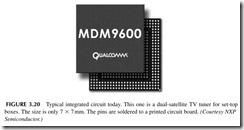
There are all sizes and types of ICs. There are linear circuits for analog sig- nals, digital circuits for binary signals, and mixed signal IC for both analog and digital signals. There are small ICs that are just an amplifier or logic circuit. Then there are even larger circuits like a computer memory or a microproces- sor that is the heart of every computer. Finally, there are complete systems on a chip (SoC). Each year, it is possible to make the components on a silicon chip smaller so you can put more on a chip economically. That is why we have
iPods, cell phones, and other really small devices that in the past would have been huge pieces of equipment. Figure 3.20 is representative of ICs today.
There are lots of other electronic components but these are the main ones.
A few others are introduced in later chapters.
While this book attempts to get you thinking about the big picture—the systems rather than the individual components—we cannot ignore discrete components completely. Well, actually we can, but you may be curious and want to have a bit more involvement with them. If so, the projects to follow will show you how individual parts are used. The circuits presented here are trivial compared with the sophisticated technology you use every day, such as big-screen LCD HDTV sets, laptops, cell phones, and your wireless Internet broadband router. Feel free to skip these if you wish.
Project 3.1
Setting Up a Simple Lab
If you want to play around with some components just to get the feel for how it used to be, you need to set up a simple lab. If you performed the previous projects, you already have a multimeter. Now you will need a way to interconnect parts in circuits and a power source.
The power source can be four AA cells in a holder. This will provide DC volt- age to power the circuits. Or you can use a common 9-volt battery. A battery clip with leads will allow you to connect the battery to the circuit.
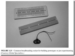
Next you will need a breadboard. This is a connector socket with multiple holes in it like that shown in Figure 3.21 . You plug the wire leads of the compo- nents into the holes to connect them to one another without soldering them.
Then you will need some components such as resistors, capacitors, and tran- sistors. In this project, the goal is to get the battery and the breadboarding socket. The remaining projects for this chapter are circuit experiments.
You can get the breadboard from a local Radio Shack or from a mail order house like Jameco. There are usually two sizes, large and small. The small one is adequate. Figure 3.21 shows a larger one.
Get a battery holder that will take four AA batteries. Again, Radio Shack or Jameco are good sources. Some battery holders also have an on/off switch but it is not necessary. They will have two leads for connecting the battery to the circuit. The 9-volt battery clip is shown in the figure.
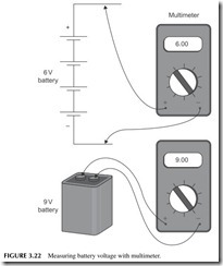
Once you get the parts, put the AA cells into the holder so that you connect the negative end (-) of one battery to the positive end (+) of the next so that the cells will be in series. That way their voltages will add together. The circuit should look like that in Figure 3.22.
Next, test the battery. Using your multimeter on the DC ranges, and measure the voltage across the battery holder wires. What do you get? You should read 6 volts or a bit more. The 9-volt battery should, of course,measure 9 volts.
Now you are ready for a few additional component projects.
Project 3.2
Light Emitting Diode
When you are buying your parts, get an LED and a set of resistors. Any old common red or green LED will work. The resistor set will be a package of all the most common values of resistors.
Project 3.2 (Continued)
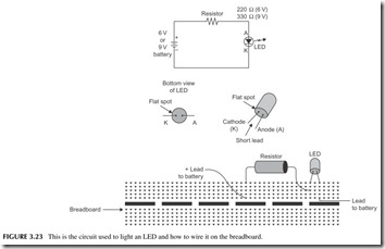
Now, wire up the circuit in Figure 3.23 . A pictorial is shown in the figure as well. Be sure to get the LED leads connected correctly, for if not, you will zap it. See the wiring details in the figure.
The resistor is needed to control or limit the current so that you do not blow out the LED. A value of 220 ohms is a good one if you use the 6-volt battery. The color code for that resistor is red-red-brown-gold. If you are using the 9-volt battery, use a 330-ohm resistor (orange-orange-brown-gold).
Wire the circuit and connect the battery. The LED should light. Now you are an electronic circuit genius.
Project 3.3
Capacitors
Capacitors store a charge and then release it. The charge is stored energy. You charge the capacitor by applying a voltage to it. Then you discharge the capacitor by connecting it to a load like a resistor. This brief project will illustrate that idea.
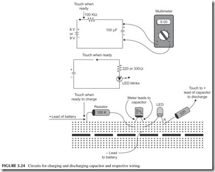
You will need the following parts from Radio Shack or another source. Get a 100-K ohm resistor (color code brown-black-yellow-gold) and a 100-μF (microfarad) electrolytic capacitor. This capacitor is polarized, meaning that you have to observe the polarity of the voltage applied to it. The wire leads are usually marked with either a + sign, or sometimes with a – sign.
Wire the circuit shown in Figure 3.24 on the breadboarding socket. Do not initially connect the positive lead of the battery to the resis- tor. Connect your multimeter across the capacitor. Now connect the 6 volts (or 9 volts) from the battery supply as indicated when you are ready to start charging the capacitor. You should see the voltage begin to rise slowly. It should take about 50 seconds for the capacitor to fully charge to 6 (or 9) volts.
Now disconnect the battery’s positive lead. The capacitor retains the charge, as you should see on the meter. It will probably begin to drop slowly as it discharges into the meter.
Now use the capacitor as a voltage source. Connect the capacitor to the resistor and LED you used earlier as shown in Figure 3.24. The capacitor will discharge quickly and you should only see the LED blink briefly. To see it again, recharge the capacitor and repeat.
Project 3.4
Transistor Switch
A transistor makes a good switch, especially a MOSFET. And it is easy to use. This project demonstrates how the MOSFET can be used to turn the LED off and on.
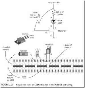
Acquire a MOSFET, such as the IRF510 or its equivalent. Then build the circuit shown in Figure 3.25 . Be sure to follow the guidelines for wiring the transistor. Use the LED and 220- (or 330-) ohm resistor that you used before.
Now, connect the battery. Touch the wire from the gate on the MOSFET to the
+6 volt or+9 connection like on the resistor. This will turn the transistor on and it will act as a switch to turn on the LED. Disconnect the gate from +6 volts and the transistor switch goes off, turning off the LED.
