How Microcomputers Work
The Brains of Every Electronic Product Today
In this Chapter:
● Microprocessors, microcomputers, and embedded controllers defined.
● The stored program concept.
● Central processors and how they work.
● Types of microcomputers.
● Modern examples of embedded controllers.
● Digital signal processing.
INTRODUCTION
Whenever you hear or see the word microcomputer, you probably think of a personal computer. A personal computer is, of course, one type of microcom- puter. But you may not be aware of other forms of microcomputers. For exam- ple, do you know that almost every piece of electronic equipment you own or use has a microcomputer in it? This type of microcomputer is called an embed- ded controller. It is usually a single integrated circuit that performs all of the basic functions of a computer but is dedicated to a specific task. Such micros (micro is short for microcomputer) are in TV sets, stereo receivers, microwave ovens, CD players, DVD players, cell phones, blenders, copiers, and most other types of electronic devices. You will find them in your car (several of them), your iPod, your bathroom scale, gasoline pumps, and dozens of other things you use every day. Microcomputers do indeed make your day—you cannot live without them.
CONCEPTS AND DEFINITIONS
A microcomputer is a small digital computer that can take several different forms. It can be a single integrated circuit, or it can be a module made up of several integrated circuits on a printed-circuit board.
The two most common types of microcomputers are the embedded micro- controller and the personal computer. One special type of microcomputer is the programmable logic controller (PLC) used for industrial control (Chapter 12).
The larger microcomputers, such as personal computers, are made with a microprocessor. A microprocessor is a large-scale integrated circuit that con- tains most of the digital logic circuitry usually associated with a digital com- puter. This logic circuitry is referred to as the central processing unit (CPU). A microprocessor is a single-chip CPU.
Another common micro is called a core. A core is a microprocessor or microcomputer integrated with some other circuits. The core is made on the same silicon chip as a cell phone or a security device. Today multicore micros are common. Two or more cores are used to get more processing power.
Embedded microcontrollers are complete micros on a single chip, including the CPU, memory, and input/output circuits. But in all cases, a microcomputer is an assembly of digital logic circuits, such as gates and flip-flops, that is used to pro- cess data. It is sometimes referred to as a data processor, or simply processor.
Data, of course, refers to the binary numbers and words the processor works with. Processing refers to the way the data is manipulated or handled. Types of processing include arithmetic, logic, sorting, translating, editing, counting, and searching. Any action taken on the data is called processing. Processing normally implies that the data is changed in some way or is used to create new data. Data that is not processed as suggested above is dealt with in other ways. Four common ways are storing, retrieving, input, or output. The data is not changed by any of these techniques.
Storing data means putting it in a safe place, like a semiconductor memory or disk drive, where it can be accessed later. Retrieving, of course, is the oppo- site of storing, or going to get the data for reuse.
Input means taking data into the computer to be stored or processed. Output means sending the data from the computer to some external device. Input and output (I/O) are ways to transmit data from one place to another.
Another feature of a microcomputer is its decision-making capability. During processing, the computer can make decisions and alter its sequence of operation. In other words, the computer can “make up its mind” based on the state of the data or outside conditions.
For example, the computer can tell if a number is less than, greater than, or equal to another. It can choose among alternative courses of actions or say yes or no, true or false, if given enough input facts.
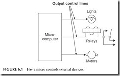
Another major application of computers is control. Computers can be used to actuate relays and solenoids or turn lights and motors off and on (see Figure 6.1). In control applications, the computer actually determines when external devices are turned on or off. The computer serves as an electronic clock to time various operations. One example is the embedded single-chip microcon- troller inside a microwave oven or a washing machine. Another example is a programmable logic controller (PLC), a special type of microcomputer used
in industrial applications, that is commonly used to sense, sequence, and time operations in a factory.
The most important thing to remember is that the control is automatic. The micro knows when to perform the various operations that it has been assigned because it has been programmed to do so.
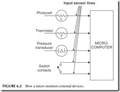
In order to implement certain control applications, the micro must also per- form a monitoring function. The micro “looks at” the process or devices being controlled to see what is happening. For example, the computer can monitor switch closures to determine physical state or position, pressure, and many other parameters. Transducers (sensors) convert the monitored physical char- acteristics, such as temperature or light level, into electrical signals that the computer can understand and respond to (see Figure 6.2 ). In most microcon- trollers or PLCs, the controlled output change takes place only if a specific
input condition is sensed or not sensed. For example, if a temperature sensor indicates that the temperature has risen to a specific level, the computer will turn on a cooling fan.
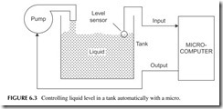
Micros sometimes change the control function in response to one or more of the inputs they are monitoring. For example, if the micro senses that the liquid in a tank exceeds a given level, it can automatically turn off the pump that is filling the tank. If the liquid level goes below a predetermined level, the micro detects this and automatically starts the pump (see Figure 6.3). The key point here is that the computer makes its own decisions based on the input data that it receives. The result is full automation of some process or device.
The micro’s ability to monitor and control operation may be used to auto- mate simple processes in a toy or to operate entire factories.
COMPUTER ORGANIZATION AND OPERATION
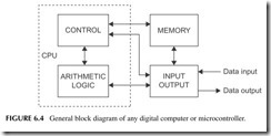
All microcomputers are made up of four basic sections: memory, control unit, arithmetic-logic unit, and I/O unit. A general block diagram of a microcomputer showing these four sections is given in Figure 6.4. These four sections commu- nicate with one another over multiple parallel electrical conductor data paths called a bus, as shown, to process the data or perform a control function.
Note that the control and arithmetic-logic unit (ALU) are shown together in a common structure. This is the central processing unit (CPU). The CPU is, of course, usually a microprocessor.
The memory is that part of the computer where data and programs are stored. The memory in any computer may contain thousands, millions, or even billions of locations used for storing numbers, words, or other forms of information.
Two primary types of information are stored in computer memory. The first type is the data to be processed. These are the codes, numbers, letters, and other forms of data to be manipulated.
The other type of data stored in memory is an instruction. Instructions are special binary numbers or codes that tell the computer what to do. Instructions specify the ways in which the data is to be processed. For instance, there are instructions that cause arithmetic operations to take place or data to be trans- ferred from one place to another.
The instructions listed in a special sequence form a program. A program is a list of instructions that causes data to be processed in a unique way. A program is a step-by-step procedure that solves a problem, performs a control operation, or otherwise manipulates data according to some recipe. Programs are stored in memory along with the data that they process. In some micros there are separate memories for data and instructions. The programs that a computer uses are called software.
Data and instructions can be stored in or retrieved from memory during processing. When data is stored, we say that it is written into memory. When data is retrieved, we say that it is read from memory. A typical write operation transfers data from an analog-to-digital converter and stores it in memory. A common read operation accesses data in memory to be transferred to an LCD screen.
Now let’s look at the operation of the CPU. The control unit is that portion of the digital computer responsible for the automatic operation. The control unit sequentially examines the instructions in a program and issues signals to the other sections of the computer that carry out designated operations.
Each instruction is fetched (read) from memory by the control unit, inter- preted, and then executed one at a time until the program is completed. This is called the fetch-execute cycle, which is repeated on each instruction until the program runs to completion. The execution of each instruction may call for accessing one or more data words in the memory or storing a data word in memory.
The ALU is the section of the computer that carries out many of the func- tions that are specified by the instructions. In other words, the ALU actu- ally processes the data. Specifically, the ALU carries out two main types of
processing: arithmetic operations (such as addition, subtraction, multiplication, and division) or logic operations (such as AND, OR, complement, or exclusive OR). For example, if an add instruction is stored in memory, the control sec- tion will fetch it, interpret it, and send signals to the ALU that cause two num- bers to be added.
The ALU also performs data movement operations. It can move data or instruction words from one place to another inside the CPU or it can carry out memory read/write or input/output operations. These are called load and store instructions.
A key part of the CPU associated with the ALU is the registers. Most ALUs have two or more registers. High-powered CPUs may have a group of 16 or more registers, called general-purpose registers (GPRs). The reg- isters are used to temporarily store the data being processed by the ALU and the results of the computations. Other registers in the CPU store a number called an address where the data or instructions are stored, store the instruction being executed, or act as a stop-off place for data into or out of the CPU.
The control section, ALU, and the registers in all micros are very closely related. They operate together and are always considered as a single unit. As indicated earlier, the combination of the control and the ALU sections is called the CPU (see Figure 6.4). In addition, microprocessors are single-chip CPUs. Besides being called CPUs, microprocessors are sometimes called MPUs or microprocessing units. You will also see the expression μP used to refer to a microprocessor. The μ is the Greek letter mu, which means micro; theP means processor.
A microcomputer consists of a microprocessor (the CPU) plus external memory and I/O circuits. Or it could be an embedded controller with every- thing on one chip. The memory is either SRAM or DRAM for data and pro- grams and EEPROM or flash for the program.
The I/O unit of the computer is the set of logic circuits that permits the CPU and memory to communicate with the outside world. The I/O circuits are referred to as interfaces. All data transfers into and out of the computer pass through the I/O interfaces.
The external peripheral devices, or peripherals, connected to the I/O unit are electronic or electromechanical units that are used for data entry or data display. Data is most commonly entered into the computer through an input keyboard or a disk drive.
The output data is usually displayed on a video monitor or small LCD screen. “Hard copy” on paper is created by a printer. There are a wide variety of other external input/output devices such as scanners, voice synthesizers, and barcode readers.
In an embedded microcontroller, the peripheral devices include keyboard, ADC, sensors, magnetic stripe readers, barcode scanner, and so on. Outputs go to relays, motors, lights, and liquid crystal displays (LCDs).
OPERATIONAL DETAILS
Registers and the ALU
The main circuit element in a CPU is the register. Usually the data to be pro- cessed by the CPU is taken from memory and stored temporarily in a register. Like a memory location, a register usually has a fixed length such as 8, 16, or 32 bits. But unlike a memory location, registers are often used to manipulate data as well as store it. That is, the register can alter or process the data in some way.
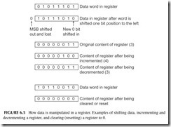
Examples of how a register can process data are shown in Figure 6.5. A binary word in a register can be shifted one or more bit positions to the right or left, or the register may be connected as an up/down counter so that it can be incremented (add one to the content) or decremented (subtract one from the content). A register can also be reset or cleared, thereby erasing any data in it and leaving the content zero.
Data transfers and manipulations performed on a register are initiated by individual computer instructions. For example, one instruction may cause the register to be loaded from a memory location. Another instruction may cause the word in the register to be transferred to a memory location. All data trans- fers are parallel, meaning that all bits are moved simultaneously from the source to the destination.
The main working register in most digital computers is called the accu- mulator. It may also be called the A register, W register, or something else.
The accumulator can hold one word whose bit length is equal to that of a memory location. An 8-bit microprocessor has an 8-bit accumulator. The accu- mulator is part of the ALU.
The accumulator can be loaded from memory or the accumulator content can be stored in any memory location. I/O operations with peripheral units sometimes also take place through the accumulator.
Data to be processed by the arithmetic/logic section is usually held in the accumulator. This data is fed to the ALU. The ALU is a digital logic circuit that can add, subtract, and perform a wide variety of logic operations.
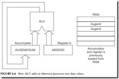
The ALU is capable of processing two inputs, one from the accumulator and one from the memory of another register (see Figure 6.6). Let’s assume that you wish to add two binary numbers. To do this, you first load one of the numbers (the augend) into the accumulator. This is done with a load- accumulator instruction that takes the number from a memory location and puts it into the accumulator. Next, an ADD instruction is executed. This causes another word (the addend) to be taken from memory and placed in register B. It is then added to the content of the accumulator. The sum is usually stored back in the accumulator, replacing the augend originally there.
Some microprocessors have two or more accumulator registers that share a single ALU. Two accumulators provide greater flexibility in the manipula- tion of data than a single accumulator. Such multiple registers simplify, speed up, and shorten a program to perform a given operation. Some sophisticated CPUs have 4, 8, 16, or even more accumulators. Usually they are referred to as GPRs or a register file. These registers can each use the ALU and act as tem- porary storage locations for data and the intermediate results of calculations. Instructions are provided to move data from one register to another.
In most micros, the GPRs share a single ALU. The ALU accepts only two input words and generates a single output word. The two words to be processed by the ALU usually come from any two GPRs or any GPR and a designated memory location. The destination of the ALU output can also be one of the GPRs in some CPUs.
Control Unit
CPUs also have several other registers, including the instruction register; the program counter, also called the instruction counter; and the memory address register, also called the address buffer.
The instruction register (IR) is used to store the instruction word. When the CPU fetches an instruction from memory, it is temporarily stored in the IR. The instruction is a binary word or code that defines a specific operation to be performed. The instruction word is also called the op code or operation code. The CPU decodes the instruction, and then executes it.
The program counter (PC) is really a counter and a register. It stores a binary word that is used as the address for accessing the instructions in a program. If a program begins with an instruction stored in memory location 43, the PC is first loaded with the address 43. The address in the PC is applied to the memory, causing the instruction in location 43 to be fetched and executed. After the instruction is executed, the PC is incremented (add 1) to the next address in sequence, or 44. The instructions in a program are stored in sequential memory locations.
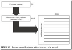
The memory address register (MAR) or address buffer also stores the address that references memory. This register directly drives the address bus and the memory address decoder in RAM or ROM. The MAR gets input from the PC when an instruction is to be accessed (see Figure 6.7 ). The MAR can also be loaded with an address that is used to access data words stored in memory. To retrieve a data word used in an arithmetic operation, the MAR is loaded with the binary word that points to the location of that word in RAM. This address is often a part of the instruction.
It is important to note that the PC and the MAR (address buffer) have a fixed length of so many bits. And that limits the amount of memory that can be accessed. For example, with a 16-bit address register, the address bus has 16 bits to address RAM and ROM. With 16 bits, a maximum of 216 = 65,536 words can be addressed.
There are usually two other registers, the flag and stack pointer registers. The flag or F register is an 8-bit register whose individual flip-flops are set and reset by the ALU as the various arithmetic and logic operations are carried out. Each flip-flop is called a flag. As an example, there are zero (Z) and carry (C) flags. If the accumulator content is zero after an operation is performed, the Z flag is set indicating this condition. If an arithmetic operation (addition) results in a carry from the MSB of the accumulator, the C flag is set indicating this
condition. These flags can be monitored or tested by the control circuitry to change the sequence of processing.
The stack register is a 16-bit or larger register used to address a selected area of RAM known as the stack. This memory is used to store register con- tents and status information when subroutines and interrupts are used.
Instruction-Word Formats
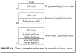
There are three types of instruction formats used in typical 8-bit microproces- sors, illustrated in Figure 6.8. In the single-word format, the instruction is a single 8-bit word. This word is called the op code. The op code tells the ALU, the registers, and other elements of the system what to do. In this format, no address is used. The focus of the instruction is implied in the instruction. That is, the data to be processed is already in a location designated by the instruc- tion. Usually the data is in a register. Typical instructions using this format are register-to-register transfer, shift data left (or right), or clear to zero.
The two-word instruction format in Figure 6.8 requires two 8-bit words to define the operation. These two words are stored in sequential memory loca- tions. The first word is the op code. The second word is usually an address that specifies a memory location where the data word to be processed is stored. For example, if the op code calls for an add operation, the address word designates the location in RAM of the number to be added to the contents of the accumu- lator. The 256 bytes of RAM can be addressed with 1 byte of address.
In some 2-byte instructions, the second byte is not the address. Instead, it is the data itself. This is called an immediate instruction since it is not necessary to address the data that is available immediately within the instruction itself.
The three-word instruction format in Figure 6.8 is comprised of an 8-bit op code and two 8-bit address words stored in sequential memory locations. The second and third bytes together form a 16-bit address word that designates the location in RAM of the data to be processed. In the 3-byte instruction for- mat, the first byte is the op code, the second byte is the least significant half of the address, while the third byte is the most significant part of the address. Different formats are used by other micros.
To access a word in RAM, the instruction address word must be stored in the MAR. This happens during the instruction fetch operation. When an instruction is fetched from memory, the op code is stored in the instruction register while the address is stored in the MAR. The instruction is then executed. The MAR usually gets its input from the PC. Once an instruction is fetched and executed, the PC is incremented.
The PC may be incremented once, twice, or three times, depending on the length of the instruction just executed. If a 2-byte instruction is executed, the PC is incremented twice so that the PC points to the address of the next instruction op code.
Program Execution Example
Now let’s illustrate how a typical CPU executes a simple program. Here are a few common instructions similar to those found in any micro.
Move A to B (MOV B,A): This is a 1-byte instruction that causes the content of the accumulator (A) to be moved to register B. The content of the accumulator is not erased.
Load Accumulator (LDA): This is a 3-byte instruction that takes the content of the address specified by the second and third bytes and loads it into the accumulator.
Add Immediate (ADI): This is a 2-byte instruction that takes the content of the second byte of the instruction and adds it to the content of the accumu- lator. The sum is stored in the accumulator, replacing the number that was there previously.
Halt (HLT): Halt is a 1-byte instruction that stops processing.
Note that we refer to each instruction by a three-letter abbreviation called a
mnemonic.
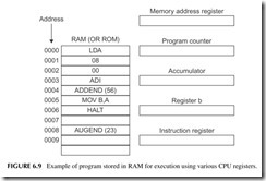
Figure 6.9 shows a complete CPU and the RAM containing a simple pro- gram. The first instruction in the program is the LDA stored in location 0000.
To begin the execution, the address of the first instruction is loaded into the PC that points to the location of the instructions in RAM.
Next, the content of the PC is transferred to the MAR that addresses RAM. The LDA instruction op code is fetched and stored in the instruction register. The address bytes of the LDA instruction in locations 0001 and 0002 are then trans- ferred to the memory address register. The address of the data to be loaded into the accumulator in bytes 2 and 3 is 0008. The desired data word in location 0008 is retrieved and loaded into the accumulator. This is the augend (23).
After the LDA instruction is executed, the number 23 is stored in the accumulator. Next, the PC is incremented three times. The ADI instruction is then fetched and stored in the instruction register. The number to be added is stored in location 0004.
This is an ADD immediate instruction where the second byte contains the data, in this case the addend (56). The number in location 0004H is 56, which is added to 23 in the accumulator, creating the sum 79. The mnemonic of the next instruction to be executed is MOV B,A in location 0005.
The sum in the accumulator is then moved to the B register by the MOV B,A instruction. The content of the accumulator is not changed when data is transferred to the B register.
The PC is incremented once since the HLT is a 1-byte instruction.
As you can see by this step-by-step analysis of the execution of a computer program, there is nothing mysterious about its operation. The CPU simply fetches and then executes the sequentially stored instructions at very high speed until the operation is complete. This process is sometimes referred to as the stored program concept.
Microcomputer Buses
Data transfers inside a microprocessor take place in parallel. This means that all bits in a word are transferred simultaneously from one place to another. It takes only a few nanoseconds (one billionth of a second) for all data bits in one register to be moved to another register.
The parallel data transfers take place over a data bus. A bus is simply mul- tiple parallel electrical connections from a source to a destination. A number of these buses are contained within the CPU and are known as internal buses.
Microprocessors usually have three major buses—a data bus, an address bus, and a control bus. These are made available to external circuits in some micros. A typical 8-bit CPU has an 8-bit data bus and a 16-bit address bus. The data bus sends data to and from the CPU, RAM, ROM, and I/O sections. All data transfers between the CPU and memory or I/O sections take place over the data bus. The address bus drives all of the memory and I/O devices.
When an instruction is fetched from RAM or ROM, it is transferred over the data bus from the memory into the instruction register. Any data word retrieved from memory or a peripheral device via the input section also passes over the data bus into the accumulator or GPR.
When a store instruction is executed, the word in the accumulator is transmitted over the data bus into RAM. Data can also be transferred from the accumulator over the data bus to an external device such as an LCD. Or, data from an input device such as a keyboard passes over the data bus and is placed into the accumulator. The important point here is that data can move in either direction over the data bus. We say that it is a bidirectional bus.
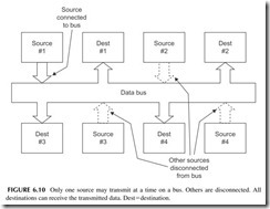
Another key point is that the data bus can be connected to only one data source at a time. Data can originate only at a single source, but it can be sent to one or more destinations. To accomplish this, circuits called bus multiplexers, or three-state line-driver circuits, are used to connect or disconnect the various data sources to or from the bus. Figure 6.10 illustrates this concept.
The address bus is a unidirectional bus. It transfers an address from the CPU to all external circuits (memory and I/O). Address words are produced in the CPU. The PC generates the address that points to the instruction to be fetched. The content of the PC is transferred over a parallel 16-bit internal
address bus to the memory address register or address buffer. The output of the MAR or address buffer is the address bus.
The control bus consists of numerous signals generated by the micropro- cessor and used to initiate various memory or I/O operations. The control bus also contains input lines from external circuits that tell the CPU what to do and when. The number of control signals varies from CPU to CPU.
POPULAR MICROS
The first practical microprocessors and microcomputers became available in the mid-1970s. Over the years lots of different models have been developed. As semiconductor processing technology has improved over the years, it has become easier and cheaper to put more circuits on a chip plus the memory that earlier was always external. And processing speeds have multiplied many times over. Today’s embedded controllers are indeed complete computers on a chip and they run at very high clock rates. And their cost is low. In high-volume manufacturing, an embedded controller can cost less than $1.
Most of the initial processors were 8-bit devices. These are still popular today. Larger, faster processors are available for not much additional cost. Sixteen- and 32-bit processors are commonplace. Even 64-bit devices are available if needed. Many are individual chips, while others are available only as cores on a larger systems chip. Following is a summary of a few of the most widely used processors.
8- and 16-Bit Microcontrollers
8051
The 8051 is one of the oldest but still widely used. It was originally developed by Intel in the late 1970s and 1980s. It is still around and available from a half dozen or more companies. The more recent versions are faster and have more memory and I/O features than the original. Original clock speeds were only 8 to 12 MHz, but today you can get models with a clock rate up to 100 MHz.
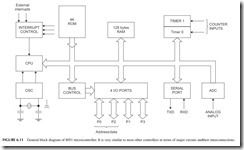
A general block diagram of the 8051 is given in Figure 6.11. The 8051 features an internal RAM of 128 or 256 bytes but can handle 64 or 128 KB of RAM externally. The internal ROM can be had from 512 bytes to 128 KB. Some models also feature flash memory. As for I/O ports, the figure shows four 8-bit parallel I/O ports. You can get a standard serial port called a UART, and more specialized I/O ports such as SPI and I2C. See the Interfaces sidebar in this chapter. Many models also come with an internal 10- or 12-bit ADC.
A few other items in this diagram that were not previously discussed are the clock, interrupts, and timers. The clock is an oscillator that controls all operations in the micro. Its frequency is usually set by an external crystal that maintains a precise and stable frequency. The higher the frequency, the faster the operations. Fast is good.
An interrupt is, as its name implies, an external signal that can interrupt the CPU when an important event occurs. It can signal the CPU of the event and even cause the CPU to stop executing the current program and jump off to another program to deal with the interrupt.
Timers are usually just one or more up/down counters than can be pro- grammed with various count values. These are used to implement count functions in programs and to provide timing operations for I/O operations. Most controllers have one or more timers.
68HC11
Another widely used 8-bit controller is the Freescale 68HC11 and its various versions. There are dozens of offshoots and variations. It has two 8-bit accu- mulators and one 16-bit accumulator. Total memory space is 64 KB with 128, 256, or 512 bytes of RAM, and up to 48 KB of ROM program memory. Different versions have all the interfaces, both parallel and serial, and some models have a built-in 8-bit ADC. A 16-bit version called the 68HC12 is also part of the product mix.
PIC Processors
Microchip Technology makes one of the most widely used 8-bit controllers. Called PIC processors, they are extremely simple and cheap. There are hun- dreds of versions with different memory sizes and configurations and various mixes of interfaces. One of the simpler versions is the 16C54. It has a single
working register, W, that is the accumulator. It uses a bank of 24 to 73 regis- ters for RAM. ROM for program storage ranges from 512 bytes to 2 KB. I/O occurs via 4- or 8-bit parallel ports. Larger versions have more RAM and more ROM, higher clock speeds, a built-in ADC, and special network interfaces like CAN. Several 16-bit versions are also available.
MPS430
A typical 16-bit microcontroller is the Texas Instruments MSP430. It has 16 GPRs and a clock speed of 16 MHz. On-chip RAM is SRAM, and can be had in versions with 128 bytes to 10 KB. ROM for the program is flash from 1 KB to 120 KB. It has an ADC on board, a DAC, timers, and all the common serial interfaces. It is a popular chip because its low power consumption makes it ideal for portable and battery-powered devices.
32- and 64-Bit Processors
As it turns out, it is almost as cheap and easy to make a 32-bit processor as it is to make an 8-bit device. For that reason, for a few cents more, designers can make their products faster and more powerful by selecting a 32-bit device. With this many bits being processed at the same time, it is possible to move more data faster, compute with increased resolution, and to perform much more complex operations faster and easier. Thirty-two-bit processors can also address much more memory. A few years ago, 32-bit processors were reserved for only the largest or most critical of needs. Today, the 32-bit processor is almost as widely used as the 8-bit processor.
Three devices account for most applications. They are made by ARM Holdings, Freescale, and MIPS. ARM is the name of a British company that invented a super-simple, fast, and flexible 32-bit processor that does every- thing well at very low cost. It is referred to as a reduced instruction set com- puter (RISC) processor. It has a few simple instructions but is extremely fast. ARM does not actually make chips, but instead licenses the design to others. There are several vendors of ARM processors but most of them are actually cores that are integrated on-chip with other circuits to form a system on a chip (SoC). With over 75% of the market share, you are sure to encounter an ARM device sooner or later. Chances are you own at least one inside a product such as a cell phone, which is where most are used.
Freescale ’s PowerPC is another popular 32-bit processor. It was originally used in Apple Macintosh computers but no more. IBM used it widely and still does in some products. Many embedded versions have since been made. Its primary usage is in communications, networking, automotive, and industrial applications.
For really super processing power, the MIPS processors are a popular choice for certain embedded applications. These devices come in 32-bit as well as 64-bit models, in case you really have a hot application for which nothing else will do. The MIPS processors are great at advanced math and have excellent resolution.
Microcontroller Interfaces
An interface is the circuitry that connects an embedded controller to the outside world. Initially, all I/O in early micros was just the parallel data and address buses extended to accommodate additional I/O circuitry. Today, much of the I/O inter- face circuits are put right on the same chip with the rest of the micro. Following are the most widely used interfaces you are likely to encounter. All of these are serial interfaces. Parallel I/O is still used, but today the preference is serial I/O because of fewer interconnecting lines.
RS-232/UART—This universal asynchronous receiver-transmitter is actually the physical circuitry implementing a popular serial interface standard referred to as RS-232. It was originally developed for connecting computers to teletype machines and early video terminals. It is still used today, especially for con- necting to industrial equipment for monitoring or control.
The RS-232 interface sends and receives data in bytes (8 bits) plus two extra bits, called Start and Stop bits, that tell the receiving device when the data begins and ends (see Figure 6.12 ). The logic levels are- 3 to- 25 volts for a binary 1 and
+3 to + 25 volts for a binary 0. Typical voltage levels are in the 5- to 12-volt range. The data rate is slow, typically from 300 bps to 115.2 kbps. Standard data rates are used, so no clock signal is needed. Common speeds are 2400, 9600, and 19,200 bps. The physical communications medium is a two-wire (signal plus ground) cable that can be up to 50 feet long. Special 9- and 24-pin connectors are part of the standard. Many PCs and laptops still have a 9-pin RS-232 port.
I2C—Shorthand for inter-integrated circuit or I squared C, this is a low-speed serial bus that is used for sending data from one chip to another on the same PC board or over short cables between two pieces of equipment. The data rate is typically in the 10 kbps to 400 kbps range, but a faster version (3.4 Mbps) is
Microcontroller Interfaces (Continued)
available. Speeds rarely exceed 100 kbps. Only three wires are needed, data, a clock signal that controls the data transfer, and a ground.
SP—I This is the serial peripheral interface. It uses four wires, data in, data out, clock, and a select signal that determines whether a device is a master or slave and either sending or receiving data. A fifth connection is ground. It is much faster than the I2C interface, with speeds up to 20 Mbps.
CAN—This is controller area network serial bus in an interface used to link micros together in small networks. It is used in automotive and industrial applications. The usual cable is twisted pair and a ground. Speeds range from 10 kbps to 1 Mbps with 20 kbps being typical. The data is sent in specifically formatted frames as determined by a standard protocol. It uses start and stop bits like the RS-232 and some similar control codes defined in ASCII. It also includes error detection and correction capability, so it is very reliable.
USB—The universal serial bus is the most common PC interface for peripherals including keyboard, mouse, printer, flash drive, external disk, and so on. It is also used in some embedded micros. The interface uses two wires but also includes
+5 volts DC and ground. Version 2.0 provides speeds to 480 Mbps over cables no longer than 16 feet. A new higher-speed version 3.0 is also available with speeds up to 5 Gbps. Data is sent in bytes in packets according to a unique protocol.
RS-485—This is an interface widely used in industrial applications. It uses twisted pair cable that can be up to 4000 feet long. The cable is actually a bus to which many devices can be attached. Data rates can be up to 10 Mbps for shorter lengths. Various protocols may be used.
A WORD ABOUT SOFTWARE
The microcontroller can perform almost any digital function from the simplest logic operation to a complex mathematical calculation. The only problem is that you have to tell it to do what you want. And you do that by programming. A program is the sequence of instructions that detail the order in which you do the various processing steps that lead to your application. The controller chip itself is a dumb piece of hardware waiting for its program. What this means is that today, designing an electronic product is as much about writing programs as it is building electronic hardware.
Software is the name given to all the programs that a processor uses for devel- oping and executing a program. The program that implements your application is the applications program. Other types of software used with the processor follow:
Languages—A programming language is a set of rules or syntax that defines how you tell the processor what to do. A language is the tool that you actually use to create your application program. It is a kind of short- hand code that lets you express the operations in simple terms.
Editor—An editor is like a word processing program that lets you type in your program. You then save it as a file that the compiler or assembler uses to create machine code.
Compiler—A compiler is the program that translates your program code into binary code that can be stored in the memory and used by the processor. Processors only understand binary code but humans are not good with such code. So, you write your program in a language you can understand and the compiler converts it to the code that the processor understands.
Operating system—For large complex programs or for applications that require the processor to execute multiple programs at different times, you need a piece of software that manages the multiple programs and opera- tions. The operating system (OS) oversees things like memory usage and access, timing, and I/O operations. Not all embedded controllers need an OS, just the more powerful ones with multiple functions. For example, most cell phones have an OS.
Development environment—This is a complete package of software tools that facilitates your software development. It consists of languages and compilers, as well as programs for testing and debugging your code.
Subroutines—These are short sections of code that perform a specific opera- tion. It may be a math operation, some type of I/O process, or other function that is performed multiple times. You only write the subroutine once, and then access it when you need to do that operation. Many development systems have libraries of subroutines that you can tap so you do not have to program common functions yourself. Subroutines shorten your development time and speed execution.
Programming Languages
There are dozens of languages used from programming embedded controllers. The more popular ones are assembly language, C, and BASIC.
Assembly Language
Assembly language uses shorthand mnemonics such as three- or four-letter designations for the instructions that the processor can execute. Instead of programming with binary code, you use the mnemonics. In addition, you use names that you make up to identify memory locations, I/O ports, and other things normally referenced by a binary code. Following is what a simple assembly program looks like:
ORG $0000 LDAA FIRST MUL SECOND STA PRODUCT OUT PORT 1 END
This programs loads one number from a memory location given the name FIRST, multiplies it by another number in memory location named SECOND. It then stores the result in another memory location called PRODUCT. It next out- puts the value to an I/O port called PORT 1. The ORG $0000 simply says to start the program whose first instruction is in memory location 0000, a hex address.
The software that converts the assembly language program to binary code is the assembler. The assembler gives actual binary assignments to the memory locations named as well as the instruction op codes.
C Language
The C language is referred to as a higher-level language in that the various syntax and terminology of the language usually translates into multiple binary machine instructions. The C language lets you write the program in a more conversational or casual format using English instead of cryptic mnemonics and other terms. The language is a bit of a challenge to learn, but after that programming goes much faster. A compiler converts the C-language program code into binary code.
A simple C program may appear like this:
int x, y, z x = 38
y = 57
z = 57 – 38
printf z
The first line identifies three integer values x, y, and z; 38 is assigned to x, and 57 to y. Then the difference between the two is designated z. Finally, the printf line accesses a subroutine that causes z to be printed.
BASIC Language
Some embedded controllers use a simplified version of BASIC. BASIC was invented before personal computers and initially became the main language of personal computer programming. Microsoft still sells its Visual BASIC soft- ware for program development. BASIC is very simple higher-level language that is easy to learn and use. The program created is then translated into binary code by a compiler. Alternately, the controller runs a program called an inter- preter that resides in memory and executes the program a command at a time.
The following program is written in PBASIC, a simple version of BASIC used with an embedded controller called the BASIC Stamp made by Parallax. It uses a PIC microprocessor and stores a program in flash memory. The pro- gram causes an LED to flash off and on.
Flash Output 7
High 7
Pause 500
Low 7
Pause 500
Goto Flash
The name of this program is Flash. The first line tells the controller to make pin 7 the output port. The next line tells pin 7 to go high or to binary 1. The next command says pause for 500 milliseconds. Next, pin 7 is made to go low or to binary 0 via the Low command. Pause makes it stay there for another 500 milliseconds. Finally, the Goto command causes the program to look back and repeat itself again and again. The result is an LED that turns off and on at a 1000-millisecond (1-second) rate.
DIGITAL SIGNAL PROCESSING
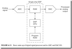
Digital signal processing (DSP) is the technique of programming a microcom- puter to perform operations normally carried out by analog or linear circuits. The method is illustrated in Figure 6.13. Assume you want to process an ana- log signal by filtering. You could use a hardware filter made up of inductors and capacitors or resistors and capacitors. Another way to do it is with DSP. The analog signal to be filtered is first digitized with an ADC and the resulting data stored in a RAM. This data is then acted upon by a processor programmed to perform a filter function. Special mathematical algorithms have been developed to do this. The resulting calculations generate new data that is also stored in the RAM. This new data is then sent to a DAC where it is converted back to an analog signal. The result is that the signal is filtered as if were processed by an electronic circuit of capacitors and inductors. The processing was mathematical. There are many other operations that can be performed by DSP. Filtering is the main application, but you can also do things like modulation and demod- ulation as needed in wireless applications. It will perform other things such as data compression, equalization, tone control, and even frequency analysis.
Using a program called the fast Fourier transform (FFT), the DSP can analyze a signal and tell you exactly what frequency components are in it. It identifies the harmonic frequencies and their various amplitudes and phases just as in a frequency-domain plot.
The big question is why use a complicated technique such as DSP when you can do it with simple analog/linear hardware? Probably the best answer is “just because we can.” With cheap single-chip processors, DSP is often no more expensive than an equivalent analog circuit. Since everything else is dig- ital these days, it makes some sense to do as many analog functions digitally as well. But the best reason is that DSP provides superior results over analog methods. Filtering is substantially improved with better selectivity that was not possible with analog filters.
While DSP can be programmed on any processor or controller, it is best done on special DSP chips designed for the purpose. They use special archi- tectures and processing schemes to speed up and improve the processing over standard conventional processors. A good example is that DSP chips imple- ment a multiply and add or accumulate function, called MAC, that is common to most DSP processes. The MAC has to be programmed in a standard proces- sor, but in a DSP chip it is implemented with special hardware that speeds up the process and simplifies programming. Some more conventional processors also incorporate DSP instructions to facilitate DSP operations.
Now that DSP chips are cheap despite their complexity and speed, DSP is widely used. It is found in most electronic products today, such as TV sets, cell phones, MP3 players, cable modems, and many other common products.
Project 6.1
Use a Microcontroller
One of the fastest ways to get familiar with a microcontroller is to use the BASIC Stamp made by Parallax. It comes as a complete unit with a microchip technology PIC processor and I/O circuits. One is a USB port to a personal computer. The soft- ware provided lets you program the controller in PBASIC. You write the program on a personal computer and download it to the EEPROM in the PIC. Then you run the program. It is ideal as a way to monitor and control lots of simple devices. And it is a fast and easy way to see firsthand what a controller does.
Go to the Parallax website at www.parallax.com and find the BASIC Stamp info and just order one. There are various models, from the ultra simple to the complex, and lots of accessories to help you implement various applications.
Project 6.2
Learn More about DSP
Go to the Texas Instruments website at www.ti.com. TI is the leader in DSP chips and has lots of useful information for your learning purposes.
