Radio/Wireless
The Invisible Cables of Modern Electronics
In this Chapter:
● The oldest electronic application.
● What are radio waves?
● The electromagnetic frequency spectrum.
● The hardware of radio: transmitters, receivers, and antennas.
● Two-way radio applications.
● Satellites.
● Radio telescopes.
INTRODUCTION
First they called it wireless. Then they called it radio. Today, the term wireless is trendy again. Whatever you call it, radio is communication over a distance without any physical connection. Radio is cool because it is completely silent and invisible. It can occur over a distance of only a few feet, all the way around the world, or between planets and spacecraft. Radio, despite the fact that it has been around for over a century, and the fact that we take it for granted on a grand scale, is truly black magic. When you finish reading this chapter, you will know how this magic works.
RADIO COMMUNICATION SYSTEMS
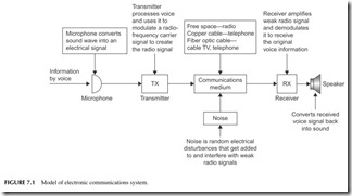
Radio is an electronic communications system. All electronic communica- tions systems have the basic form shown in Figure 7.1, whether it is a wired or wireless system. The information to be communicated, usually voice, is first converted into an electrical signal by a microphone. That signal is then processed by the circuits in a transmitter (TX), and then sent via a commu- nications medium to a receiver (RX) that processes the signal and converts it back into voice by a speaker or headphones. In the telephone system, the communications medium is a cable made of copper wire. In a cable TV sys- tem, the medium is a coaxial cable, twisted-pair cable, or fiber optic cable. But in radio, the communications channel is free space. The radio signal travels from one place to another almost instantaneously and it passes right through
most obstructions like walls, buildings, smog, trees, and even people. Note that noise is added to the signal as it passes through the channel or medium.
Noise
Noise is any random electrical voltage that interferes with the weak radio signal. Noise comes from the atmosphere, space, human-made objects, and electronic components. Atmospheric noise is lightning. Space noise comprises random signals from the Sun and remote stars. Human-made noise comes from electri- cal power generation, distribution, and switching. It also comes from fluorescent lights, motors, auto ignitions, and many other sources. The worst noise comes from the electronic components that actually process the weak radio signal. Resistors, transistors, and integrated circuits generate random noise because of thermal agitation. Heat produces random movement of the electrons in the com- ponents, and that produces a noise voltage which is added to the radio signal. Even though noise voltages are very small (microvolts or nanovolts), they are still large enough to interfere with and in some cases obliterate the very small received radio signal. In most radio systems, it is noise that limits intelligibility, transmitted data speed, and transmitted distances.
THREE BASIC WAYS OF COMMUNICATIONS
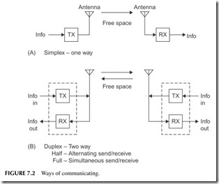
Radio communications systems work in one of three basic ways, simplex, half duplex, and full duplex (see Figure 7.2).
Simplex
Simplex is one-way communications. Examples are radio broadcasting, pag- ing, and remote control. A radio telescope is also one-way: there is a transmit- ter at one end and a receiver at the other.
Half Duplex
Duplex means two-way, and most radio communications are really two-way affairs. There is a transmitter and a receiver at both ends of the communica- tions system. Both parties can send and receive. And there are two types of duplex systems, half duplex and full duplex.
In half-duplex systems, only one party can transmit at a time. Those com- municating with one another take turns talking. This is the kind of radio where you have to say “over” or “come back” after you finish speaking to let the other party know that it is time for her or him to talk. CB radio is like this. Most two-way communications services (police, fire, taxi, aircraft, marine, etc.) use this method because it is cheap and simple. Fax machines are half duplex. Most computer modems are half duplex.
Full Duplex
Full duplex is more complex and expensive. This is two-way radio where both parties can both send and receive simultaneously. Probably the best example of this is a cordless or cellular telephone. It is great to be able to talk and listen at the same time.
WHAT IS A RADIO WAVE ANYWAY?
Any discussion of radio always gets around to this basic question. How do you describe something that you cannot see, feel, or hear? You imagine it.
Electric and Magnetic Fields
A radio wave is an invisible force field that is made up of both a magnetic field and an electric field. In combination, we call them an electromagnetic field. We can’t see or feel them, but we can experience their effects. In Chapter 2, electric and magnetic fields are described briefly. To review, a magnetic field is a force generated by a magnet, either a permanent magnet or electromag- net. Current flow in a wire or other conductor produces the magnetic field. Invisible magnetic flux lines emanate from the magnet and may influence objects in or near them.
An electric field derives from a voltage, or what we call a potential, across two conductors. The attraction of the positive and negative charges across an
open space introduces another kind of invisible field that can also influence external objects.
Now if you combine these two types of fields into a self-supporting entity, you would have an electromagnetic field or radio wave. We create a radio sig- nal with the circuits in a transmitter, but it is the magic of a device called an antenna that produces the combined electric and magnetic field that we refer to as a radio wave.
In the 19th century, a British scientist named James Clerk Maxwell figured out that if you generate a changing electric field, it would, in turn, generate a magnetic field. If the magnetic field is changing and moving forward, it will generate an electric field. The two fields support or regenerate one another as they change and move outward from the antenna that produces them. Maxwell expressed his theories in his famous mathematical equations that form the foundation of radio and light transmission.
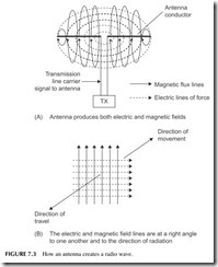
Trying to draw a picture of a radio wave is somewhat like trying to draw a picture of the wind. Nevertheless, Figure 7.3A is an attempt. Try to think in three dimensions. Current flow in the antenna wire creates the magnetic field lines. The voltage across the two segments of the antenna produces the electric field lines. The picture is somewhat simplified if we just show the field lines as in Figure 7.3B. The electric and magnetic field lines are always at right angles (90 degrees) to one another. The radio wave moves in a direction at a right angle to both field lines, in this case either into or out of the page. As it gets some distance from the antenna, it becomes self-supporting. That is, the mag- netic field sustains the generation of the electric field and vice versa.
Polarization
Polarization of a radio wave means how it is oriented with respect to the surface of the Earth. If the electric field is vertical to the surface of the Earth, the wave is verti- cally polarized. If the electric field is horizontal to the Earth, the wave is horizon- tally polarized. It is the orientation of the antenna generating the radio signal that determines the polarization. A vertical antenna produces vertical polarization, and a horizontal antenna produces horizontal polarization. For the best reception, the transmitting and receiving antennas should both be either vertical or horizontal.
There is also circular polarization. Some antennas make the signal rotate clockwise or counterclockwise as the signal travels from transmitter to receiver. Clockwise rotation, as viewed from the transmitter, is called right-hand circular polarization (RHCP). Counterclockwise rotation is called left-hand circular polari- zation (LHCP).
Signal Speed
Radio waves travel at the speed of light in space. That is 300,000,000 meters per second or 186,410 miles per second. So while radio transmission is not
instantaneous, it is pretty fast. Just as an example, to transmit a signal to the moon that is 250,000 miles away takes 250,000/186,400 = 1.34 seconds.
Signal Strength
As the radio wave gets farther and farther from the antenna, it gets weaker and weaker. The power in a radio wave, in fact, decreases by the square of the distance from the antenna. For example, doubling the distance decreases the received power by two squared (22 ) or four. Even when the transmit- ter puts many hundreds or thousands of watts of power into the antenna, the signal received at a distance is many times smaller. Typical radio signals are usually expressed in terms of microwatts (1-millionth of a watt) or nanowatts (1-billionth of a watt).
As the radio wave encounters a receiving antenna, the magnetic and elec- tric fields induce a voltage into the antenna. This tiny voltage is then amplified and translated back into the original information signal by the receiver.
ELECTROMAGNETIC FREQUENCY SPECTRUM
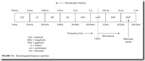
The radio signal applied to the antenna by the transmitter is a sine wave. Remember that all sine waves have both an amplitude and a frequency. Frequency is stated in terms of cycles per second or hertz (Hz). Radio trans- missions can take place over a very wide frequency range. We call this range the electromagnetic frequency spectrum. It extends from approximately 10 kHz to 300 MHz. Figure 7.4 shows a diagram designating the major divisions of the electromagnetic spectrum.
The electromagnetic spectrum is in free space, not only here on Earth but throughout the universe. The spectrum space may be used by anyone and, in fact, on Earth we all share it. The spectrum is divided up and used for many different radio services. It is also partitioned such that various frequency ranges are assigned to or used by different countries for their various radio services. In many cases, portions of the frequency spectrum are shared concur- rently among several countries. This allocation of the frequency spectrum is necessary to prevent radio stations from interfering with one another.
In the United States, the frequency spectrum is regulated by the Federal Communications Commission (FCC). Congress established the Communications Act of 1934, which has subsequently been amended to permit the FCC to reg- ulate all forms of radio and wired (telephone, cable TV, etc.) communications services. The National Telecommunications Information Administration (NTIA) manages the spectrum for the government and the military. Throughout the world, the frequency spectrum is allocated and managed by a worldwide organi- zation known as the International Telecommunications Union (ITU).
Major Segments of the Frequency Spectrum
30 kHz to 300 kHz—Low frequencies (LF)
300 kHz to 3 MHz—Medium frequencies (MF)
3 MHz to 30 MHz—High frequencies (HF) or shortwaves 30 MHz to 300 MHz—Very-high frequencies (VHF)
300 MHz to 3 GHz—Ultra-high frequencies (UHF) 3 GHz to 30 GHz—Super-high frequencies (SHF)
30 GHz to 300 GHz—Extremely high frequencies (EHF)
The various areas of the frequency spectrum are assigned to different types of communications services. For example, in the low-frequency (LF) range, most communications services are navigational systems used by the Coast Guard and military. The AM broadcast band (530 kHz to 1710 kHz) is in the
medium-frequency (MF) range. Shortwave (SW) radio broadcasts, CB radio, amateur radio, and a variety of other communications services are in the 3 to 30 MHz or high-frequency (HF) range.
One of the most widely used areas of the spectrum is the VHF range from 30 to 300 MHz.Virtually all two-way radio communications for marine, aircraft, mobile, and other services are in this range. FM broadcasting (88 to 108 MHz) and TV channels 2 through 7 are also in this region.
The UHF frequency range, from 300 MHz to 3000 MHz (3 GHz), also con- tains a wide variety of communications services. It includes two-way mobile radio, TV, and cellular telephone.
Frequencies above 1 GHz are designated as microwaves. In the microwave region between 1 and 3 GHz are satellite and navigational systems. For exam- ple, the widely used global positioning system (GPS) operates in this range. This area is also occupied by the newer cellular telephone service and wireless networks such as Wi-Fi and Bluetooth.
The frequencies from 30 GHz to 300 GHz are called millimeter waves because their wavelength is in millimeters. These frequencies are typically used only by satellite and radar systems. Other services are point-to-point wireless data services and cellular backhaul. Some short-range wireless devices have also been defined for the 60-GHz range. These will be used in consumer applications as well as in faster wireless networks.
Critical Issue: Spectrum Space
There is only so much radio spectrum space and we must all share it. It is a true natural resource. That’s why spectrum space is regulated by governments. But we have just about used it all up. Virtually every hertz of space is spoken for. Diverse radio services compete for space. In some cases, an old service must die before a new one can begin. Sometimes space is stolen from one service to give to another, such as in the mid-1980s when the upper UHF TV channels were sacrificed to make room for cellular telephones. Lately, the U.S. government has been selling space to the highest bidders for new cell phone and other wireless services. During the recent switchover to digital TV in the United States, a huge chunk of the spectrum was freed up (108 MHz, from 698 to 806 MHz) as TV stations abandoned this region. Known as the 700-MHz band, it was auctioned off by the government for $19.6 billion for more cell phone spectrum as well as broadband wireless services and cell phone TV. The trend has been to push higher and higher in the frequency range to find more space. During the past several decades, the microwave region (above 1 GHz) has been developed. This region, in the UHF, SHF, and EHF ranges, was previ- ously used only for radar and satellites. But now it is being used and developed for digital cell phones, navigation, high-speed networking, broadband (Internet)
wireless, and digital TV.
Beyond the millimeter wave range above 300 MHz is the optical spectrum. That is, above 400 GHz, the electromagnetic radiation becomes light, namely infrared, visible light, and ultraviolet light. But that’s another story altogether.
Wavelength
While we normally use frequency to refer to location of a radio signal in the spec- trum, sometimes you will hear about frequencies or ranges of frequencies desig- nated by wavelength.
Wavelength is the actual physical length of a radio wave. It is the amount of space the wave occupies. Specifically, wavelength is the length of one cycle of the sinusoidal variation of the electromagnetic fields. If we could see the electric and magnetic fields, we could measure the distance between the maximum inten- sity points in meters (1 meter = 3.28 feet or 39.37 inches). This is the wavelength. Wavelength is also the distance that the radio wave travels in the time of one cycle.
You can determine the wavelength of a radio signal with the following simple formula:
λ= 300,000,000/f
Wavelength is represented by the Greek letter lambda (λ) and frequency in hertz is designated by the letter “f.” The value 300,000,000 is the speed of light of a radio wave in meters per second in free space. (This translates to a speed of 186,410 miles per second.)
A radio signal with a frequency of 150 MHz is expressed in hertz as 150,000,000 Hz. Therefore,
λ= 300,000,000/150,000,000 = 2 meters
If we give the frequency in megahertz, the formula can be shortened to:
λ= 300/f
For example, we can calculate the wavelength of the shortwave or high- frequency part of the spectrum (3 to 30 MHz) as follows:
λ= 300/3 = 100 meters
λ= 300/30 = 10 meters
If you rearrange the formula, you can also find the frequency if you know the wavelength:
f = 300/λ
What is the frequency of the 25-meter band? f = 300/25 = 12 MHz
RADIO WAVE PROPAGATION
Propagation refers to the way in which a radio signal travels from the transmit- ting antenna to the receiving antenna. The way the signal behaves is directly related to its frequency.
Low and Medium Frequencies
For example, in the low-frequency and medium-frequency ranges, the radio signals tend to hug the Earth as they move from transmitter to receiver. These ground wave signals can only travel relatively short distances because they are
absorbed and attenuated by the Earth, trees, buildings, and other obstructions. Depending on the frequency of operation, transmitter power, and the nature of the terrain, distances are limited to several hundred miles. Distances can be extended with greater power or if the signal travels over water.
High Frequencies
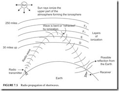
In the HF or shortwave frequency range, the ground waves are extremely weak and travel only short distances, usually several miles. Instead, propagation is by way of refraction of the ionosphere. The ionosphere is an electrified area above the Earth located from approximately 30 miles to 250 miles above the Earth. The Sun ionizes the gases in the air, thereby giving them electrical char- acteristics. The closer the ionosphere to the Sun, the greater the degree the ion- ization. The ionosphere is actually several different layers or ionization levels as shown in Figure 7.5 . The upper layers have greater ionization than the lower layers. Obviously, the degree of ionization is determined by whether it is day or night. During the daylight hours, the ionosphere is highly charged electri- cally. At night, the ion layers essentially disappear.
A radio wave in the 3- to 30-MHz range is transmitted up to the ionosphere where it is refracted or bent by ionization. The degree of bending depends on the frequency of operation and how high in the ionosphere the radio wave penetrates. In most cases, the radio wave is bent so much that it actually returns to Earth. The effect appears to be similar to that of a light beam being reflected from a mirror.
As you can see, the radio wave actually returns to the Earth at some dis- tance from the transmitter. Receiving stations in the area of the refracted signal can receive it. In some cases, if the signal is strong enough and the character- istics of the Earth are right, the radio signal may actually be reflected by the Earth back up to the ionosphere where it is again bent and returned to Earth. Under the right conditions, the radio signals can make several hops, thereby greatly extending the distance of communications. With the optimum fre- quency, power level, and time of day, communications halfway around the world can easily be achieved. That is why it is easy for you to listen to world- wide radio broadcasts that occur in the shortwave frequency bands.
VHF, UHF, and Microwaves
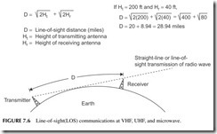
Radio wave propagation in the frequency range above 30 MHz occurs essen- tially by direct antenna-to-antenna space waves. This is usually called line- of-sight (LOS) communications. Further, the higher the frequency of the radio wave, the less it is affected by the ionosphere. UHF and microwave signals penetrate the ionosphere, making satellite and long-distance spacecraft com- munication possible.
LOS communications means that the transmitting antenna must be able to “see” the receiving antenna. If the distance of the receiving antenna is beyond the curvature of the Earth, the transmitted signal will simply pass over the antenna. To receive the signal, the receiving antenna or transmitting antenna can be increased in height, thereby extending the total range of communica- tions. Figure 7.6 shows this idea. The simple formula along with it allows you to calculate the maximum LOS communications if you know the height of the receiving and transmitting antennas. That’s why at VHF, UHF, and microwave
frequencies, the height of the antenna is the most critical determining factor in overall communications distance.
MODULATION
A radio wave is a sine wave of voltage that has been converted into electric and magnetic fields by the antenna. The transmitter generates the sine wave and amplifies it to a high power level. The question is, how does the informa- tion to be transmitted fit into this?
The information or intelligence to be conveyed is usually a voice signal produced by a microphone. Other forms of intelligence signals include pic- tures or video and digital (binary) data from a computer. The purpose of the high-frequency sine wave radio signal is to give the intelligence signal a ride. That’s why the radio signal generated by the transmitter is called the carrier. Modulation is the process by which the information is impressed on or embed- ded in the carrier. Modulation causes the carrier to be modified by the informa- tion signal.
There are three basic forms of modulation used to put information on a carrier: amplitude modulation (AM), frequency modulation (FM), and phase modulation (PM).
Amplitude Modulation
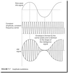
In amplitude modulation, the voltage or power level of the information sig- nal changes the amplitude of the carrier in proportion (see Figure 7.7 ). With no modulation, the AM carrier is transmitted by itself. When the modulating information signal (a sine wave) is applied, the carrier amplitude rises and falls in accordance. The carrier frequency remains constant during amplitude modulation.
Amplitude modulation is widely used in radio. AM broadcast stations are, of course, amplitude modulated. So are citizens band radios, aircraft radios, and the video modulation of a TV broadcast transmitter. A special form of amplitude modulation, known as quadrature modulation (QAM), is also widely used in modems to transmit digital data over cable or wireless.
Sidebands
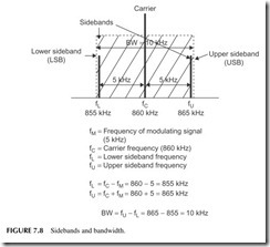
The modulation process causes new signals to be generated. These new sine wave signals are called sidebands. Their frequencies are the sum and differ- ence of the carrier and modulating signal frequencies. For example, in an AM radio station, audio frequencies as high as 5 kHz can be transmitted. If a 5-kHz sine wave tone is to be transmitted, the modulation process causes sidebands 5 kHz below and 5 kHz above the carrier to be produced. This is illustrated in Figure 7.8. For an AM radio station with a carrier frequency of 860 kHz, the
lower sideband (LSB) would occur at 860 – 5 = 855 kHz, while the upper sideband (USB) occurs at 860 + 5 = 865 kHz. The carrier and the sidebands combined produce the composite waveform shown at the bottom of Figure 7.7.
Bandwidth
This brings up the very important concept of bandwidth. Bandwidth refers to a range of frequencies over which a radio signal operates. This is also referred to as a radio channel. As you can see from Figure 7.8, the AM signal consists of the carrier and the sidebands. Together these signals occupy a bandwidth of 10 kHz. You can figure out the bandwidth of any signal by simply subtracting the lower sideband frequency from the upper sideband frequency.
BW = USB – LSB = 865 – 855 = 10 kHz
All of the receiver circuits must be set to pass signals in this 10-kHz range in order to avoid distortion of the signal or lost information.
Frequency Modulation
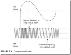
In frequency modulation, the carrier amplitude remains constant but its fre- quency is changed in accordance with the modulating signal. Specifically, the higher the amplitude of the information signal, the greater the frequency change. The actual carrier frequency deviates above and below the center car- rier frequency as the information signal amplitude varies. Figure 7.9 shows fre- quency modulation with a sine wave information signal. Note that the carrier frequency gets higher on the positive peaks and lower on the negative peaks of the information signal.
Like AM, FM also produces sidebands. But unlike AM, which produces a single pair of sidebands for each frequency in the modulating signal, the frequency-modulation process produces an infinite number of pairs of side- bands for each frequency in the information signal. As a result, the bandwidth occupied by an FM signal is enormous. Luckily, the number of sidebands produced can be controlled by properly selecting the amount of deviation per- mitted in the carrier. Small deviations result in fewer sidebands. Further, some of the higher-order sidebands are extremely low in amplitude and, therefore, contribute little to the FM signal. But while the bandwidth of an FM signal can be controlled and established to fit a desired frequency range, it does neverthe- less usually take more room in the spectrum than an AM signal.
The primary benefit of FM is that it is less sensitive to noise, which con- sists of undesirable amplitude variations that get involuntarily added to a signal. Noise is easily eliminated in an FM system where a constant carrier amplitude is used. Some of the most common applications of FM include FM radio broadcasting, and two-way mobile and marine radios.
Phase Modulation
The third type of modulation is phase modulation. Remember that phase shift is a time shift between two sine waves of the same frequency. We can use the information signal to shift the phase of the carrier with respect to the carrier ref- erence. The result of this, however, is a signal that looks virtually the same as an FM signal (Figure 7.9). Phase modulation is usually a little easier to implement electronically than FM, so most so-called FM systems typically use phase modu- lation instead. Both FM and PM are often referred as types of angle modulation.
Digital Modulation
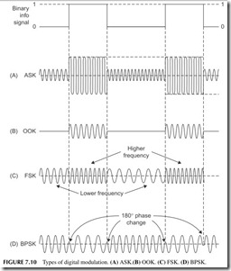
All of the three basic types of modulation, AM, FM, and PM, can also be used to transmit digital or binary data. However, they are usually given different names. Amplitude modulation of a carrier by a binary signal is usually referred to as amplitude shift keying (ASK). This is illustrated in Figure 7.10A . The binary signal simply shifts the carrier amplitude between two specific levels. A special form of ASK is called on–off keying (OOK). This is illustrated in Figure 7.10B. Here the binary signal simply turns the carrier on for a binary 1 and off for a binary 0.
Frequency modulation of a carrier by a binary signal is called frequency shift keying (FSK). Here the binary signal shifts the carrier between two dis- crete frequencies (see Figure 7.10C).
Phase modulation of a carrier by a binary signal is referred to as phase shift keying (PSK). The term binary PSK (BPSK) is also used. The phase of the carrier is changed as the binary signal switches from 0 to 1 or 1 to 0 (see Figure 7.10D). Phase shift is 180 degrees, which is easily detected at the receiver.
One of the most widely used forms of digital modulation is QAM, which is really a composite of both AM and PSK. The binary signal is converted into a multilevel digital signal that simultaneously modifies both the amplitude and the phase of the signal. QAM is used in digital data transmission in satellites and in modems sending digital data in audio form over telephone lines or cable
TV systems. It is also widely used in the newer digital wireless networks. See Chapter 8 for more detail.
Because binary signals contain many higher-frequency harmonics, the resulting signals produced by modulation have an enormous bandwidth. Many schemes have been developed to limit the spectrum of the modulating signal and, as a result, to reduce the amount of bandwidth occupied by a binary mod- ulated radio signal.
Spread Spectrum
Spread spectrum (SS) is unusual in that it is not only a form of modulation but also a system for encrypting the information signal for security purposes and for multiplexing multiple signals over a range of frequencies.
Spread spectrum was originally developed during World War II as a way to prevent the enemy from interpreting radio transmissions. For years the govern- ment and military protected the concepts of SS modulation. However, today it is widely used in radio and telephone communications. Most of the newer cel- lular telephones are based on this concept, specifically code division multiple access (CDMA) cell phones.
When using SS, the analog information signal is converted into a digital signal before transmission. The digital voice signal is then used to modify the carrier in a special way. The two most common ways of modifying the carrier are referred to as direct-sequence (DS) and frequency-hopping (FH) spread spectrum. In direct-sequence SS, the serial digital signal representing the voice is chopped up into random sequences and then used to PSK the carrier. In frequency-hopping SS, the carrier is rapidly switched from one frequency to another for a short dwell time. The result of SS modulation is that the sig- nal itself is broken up at random, and spectral energy is spread over a very wide frequency range. Because of the random sequences of the coding and fre- quency hopping, such a radio signal is nearly impossible to put back together at a receiver without knowing the code. SS receivers designed to pick up the SS signal know the code, and can unscramble the signal and reassemble it into the original modulating information signal.
RADIO HARDWARE
All radio communications systems consist of three basic pieces of hardware: transmitter, receiver, and antenna. In some systems, the transmitter and receiver are packaged and used separately, while in others they are combined into a single package and called a transceiver.
Transmitters
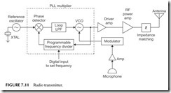
The radio signal is produced by the transmitter. A general block diagram that applies to virtually every transmitter is shown in Figure 7.11. The radio signal
is generated at a low power level by a frequency synthesizer. This uses a phase-locked loop (PLL) with a crystal (XTAL) oscillator reference. A variable-frequency divider is used to set the frequency of operation. The FCC is really fussy about the frequency at which transmitters work and, therefore, the frequency must be precisely set and extremely stable. A quartz crystal ref- erence oscillator is normally used to achieve this objective.
The low-level signal produced by the voltage-controlled oscillator (VCO) is then amplified by one or more driver amplifiers to boost the power level. Next, the microphone signal is fed to the modulator. The modulator changes the fre- quency or phase of the RF signal in accordance with the voice, digital data, or other information to be transmitted. That signal is applied to the PLL VCO.
The modulated signal is sent to additional RF power amplifiers, usually referred to as drivers. Each succeeding stage boosts the signal power by a spe- cific amount. A final RF power amplifier produces the desired amount of out- put power. From there, impedance (Z) matching circuits are used to match the high-power amplifier to the antenna for maximum power radiation.
The physical realization of the transmitter can vary all the way from a sin- gle integrated circuit chip the size of a postage stamp to something that can fill up a moderately large building. The size depends on the operating frequency and the amount of output power desired. Very-low-power, high-frequency radio transmitters for garage door openers and remote keyless entry systems on cars are fully self-contained within a single integrated circuit. High-power radio broadcast transmitters at low frequencies may fill a small room. The higher the power and the lower the frequency, the larger the transmitter.
Receivers
The job of the receiver is to translate the weak radio signal picked up by the antenna into an output that fully recovers the originally transmitted information.
By the time the radio signal reaches the receiving antenna, it is extremely weak and, therefore, the primary job of the receiver is to boost the signal level. Therefore, the receiver consists mainly of a series of amplifiers that increase the level of the small signal to a point where the original information can be recovered.
The amount of amplification provided by a receiver determines itssensitiv- ity. Another job of the receiver is to provide selectivity so that the desired signal can be picked out of the thousands of signals being transmitted simultaneously by other transmitters. The receiver’s job is to select just the desired one and to reject all of the others. This is what we refer to as the selectivity of the receiver. A third function of the receiver is to recover the original information. A circuit called a demodulator removes the voice, video, or digital data from the carrier. Finally, output amplifiers reproduce the signal as desired, such as a voice signal in a speaker.
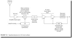
Figure 7.12 is a block diagram of a superheterodyne receiver. The incom- ing signal is usually amplified by an RF input amplifier often called a low-noise amplifier (LNA) and then fed to a circuit called amixer. The mixer is a frequency-translation circuit that converts the incoming signal, regardless of its frequency, along with its modulation to a lower intermediate frequency (IF). This allows the receiver to use a fixed-frequency amplifier system where most of the gain and selectivity of the receiver is achieved. The mixer takes the input signal and mixes it with a high-frequency sine wave signal generated internally in the receiver by what is called a local oscillator (LO). The LO is usually a frequency synthesizer. The result of the mixing is output signals that are the sum and difference frequencies of the input and oscillator signals. The IF amplifier is normally tuned to select only the difference frequency. Tuning is accomplished by changing the local oscillator frequency. The local oscillator in most channelized receivers is some type of PLL frequency synthesizer.
The IF amplifier boosts the signal level considerably. Its selectivity ensures that signals whose frequencies are above or below the desired signal are effec- tively eliminated. The IF amplifier also has a built-in feedback control circuit that automatically adjusts its gain to the level of the incoming signal. This feature is called automatic gain control (AGC). AGC permits the receiver to pick up both strong local signals and very weak distant signals. When very strong signals are received, the AGC automatically reduces the gain of the IF amplifier to minimize circuit overload and signal distortion. When very weak signals are received, the AGC adjusts the gain of the IF amplifier for higher amplification.
The demodulator circuit, sometimes called the detector, follows the IF amplifier. It removes the carrier and recovers the desired information signal. From there, additional processing takes place to either boost the signal level or to shape it before it appears at the output.
Most receivers that we are familiar with have a speaker as the primary out- put. But there are exceptions, such as the picture tube in a TV set or the motor in a garage door opener. The receiver may also put out digital data that goes straight to a computer.
Transceivers
Most communications systems use both a transmitter and a receiver. In two- way radio, both send and receive capability is needed at both ends of the com- munications channel. Therefore, the receiver and transmitter are packaged together in the same housing to create a transceiver. Small portable transceiv- ers are called hand-helds, walkie-talkies, or cellular telephones.
The transmitters and receivers are typically the same as those described earlier. However, in some cases, the transmitter and receiver may share cir- cuits. They virtually always share the antenna and a common power supply like a battery. In some cases, a single-frequency synthesizer may generate both the receiver LO signal as well as the transmitter carrier.
ISM Band Transceiver
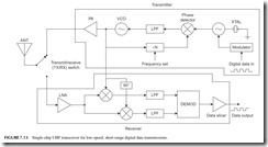
The ISM band refers to specific frequencies set aside for wireless industrial, scientific, and medical (ISM) applications. The most common frequencies in the United States are 315, 433, and 915 MHz. The frequency 868 MHz is widely used in Europe. These unlicensed frequencies are used for simple monitor and control applications using low-speed digital data over short ranges. Some com- mon examples are garage door openers, remote keyless entry on cars, remote thermometers, tire pressure gauges, security and fire alarms, home automation, and any telemetry or remote control application. The radios used for this are typically single ICs to which an antenna, a battery, a housing, and the input data are added. The devices are available as a receiver, a transmitter, or a com- plete transceiver. Figure 7.13 is a block diagram of a typical transceiver.
The transmitter section uses an external crystal to serve as the reference to an internal PLL frequency synthesizer to set the frequency. The PLL actually multiplies the crystal frequency by some N value to get the desired output. If the crystal frequency is 6.77 MHz and the divide ratio is 64, the output would be 433.28 MHz. The serial digital data input coming from a sensor, an ana- log-to-digital converter (ADC), or a computer frequency modulates the crystal oscillator to create the FSK signal. A power amplifier (PA) after the transmit VCO boosts the power up into the 1- to 100-milliwatt range. The output goes to the antenna. A transmit/receive switch allows the antenna to be shared in a half-duplex system.
The receiver is a special version of a superheterodyne. The input signal from the antenna is boosted in amplitude by the LNA and applied to the mixers. The local oscillator is set to the incoming signal frequency (also the transmit fre- quency), so the mixers generate a difference of zero. This is called direct conver- sion or zero IF. Two mixers are used and the local oscillator is shifted 90 degrees in phase between the two. This gives two zero IF outputs that are filtered. Zero IF does not mean a nonexistent output signal. It just means that the FSK sig- nal is recovered directly at its data rate. The I and Q signals are 90 degrees out
of phase and this allows the digital data to be more easily demodulated. A data slicer, a circuit like a comparator, is used to shape the signal into a clean binary bit stream. With this kind of radio, the range is limited. It may be only a few feet or up to a mile or so depending on the antenna, environment, or application.
ANTENNAS
The antenna takes the voltage and current produced by the transmitter and converts it into the electromagnetic wave we know as a radio wave. At the receiver, the antenna converts the electromagnetic field back into a voltage we know as the radio signal. The radio waves pass over the receiving antenna, inducing a voltage that causes current to flow in the receiver.
Antennas can have an amazing variety of shapes. Essentially an antenna or aerial is some arrangement of electrical conductors whose size and length are critical. For optimum operation, the antenna length must be related to the wavelength (λ) of the signal. Common antenna sizes are one-quarter (λ/4) and one-half (λ/2) wavelength at the operating frequency. The higher the frequency, the shorter the wavelength and thus the smaller the antenna. For example, one wavelength at 150 MHz, a popular two-way radio frequency range measures 2 meters. A half wavelength is 1 meter and a quarter wavelength is 0.5 meter. Since 1 meter is 39.37 inches, a half wavelength is 19.68 inches. At 900 MHz, the frequency range of cell phones, one wavelength is 0.3333 meter. A quarter wavelength antenna would be 0.3333/4 = 0.08333 meter or 3.28 inches.
Ground-Plane Antenna
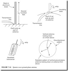
Antennas can be anywhere from a long horizontal copper wire to a vertical steel or aluminum tower several hundred feet tall. Or it may be an array of short con- ductors like those in a TV antenna. One of the most common antennas is a short quarter wavelength vertical that is widely used in mobile radios, cell phones, and other hand-held units (see Figure 7.14). The quarter-wave or ground-plane antenna as it is sometimes called, radiates equally well in all directions, making it omnidirectional. We say that its radiation or reception pattern is a circle.
Dipole
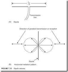
Another common antenna type is the dipole, which is one-half wavelength long and usually mounted horizontally. Figure 7.15 shows an example. Its radiation or reception pattern is a figure 8. The greatest radiation or strongest reception occurs at a right angle to the dipole element itself.
Yagi
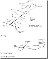
A variation of the dipole is the Yagi, a multielement antenna based on the dipole shown in Figure 7.16. To the dipole is added a reflector element that is
slightly longer than one-half wavelength, and one or more director elements that are progressively shorter than the dipole. The directors and reflector make the Yagi highly directional. The extra elements, called parasitic elements, con- centrate and aim the beam of radiation over a narrow range. At the transmit- ter, this has the effect of increasing the transmitted power, making the signal stronger at the receiver as if the transmitter power had been increased. A simi- lar gain effect occurs at the receiver.
Other Antennas
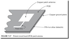
There are many other antenna variations. Antennas formed with copper pat- terns on a printed circuit board (PCB) are widely used. One example is the patch antenna (see Figure 7.17). It is simply a square area of copper about one-half wavelength on a side made on a PCB. Another is the loop antenna that is just a loop of copper on the PCB. A popular cell phone antenna is the
inverted F, which is an F-shaped pattern on the PCB. Antennas also come as components. For microwave frequencies, there are special antennas made on a ceramic base that are small and can be soldered to a PCB.
Transmission Lines
The antenna is usually connected to the transmitter or receiver by way of a coaxial cable (see Figure 7.18 ). It consists of a copper center conductor sur- rounded by an insulator, such as Teflon. Around that is a shielded copper braid or foil. The whole thing is covered with a plastic insulator. Coaxial cable is the most commonly used transmission line to connect the equipment to the antenna. It provides an efficient method of transferring the voltages and currents to and from the antenna while providing a certain amount of shielding from noise. For PCB antennas, the transmission line is just a short pair of cop- per lines from the transceiver IC to the antenna.
Microwave Antennas and Waveguides
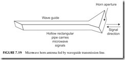
Antennas used at microwave frequencies are quite different from those used at the lower frequencies. Perhaps the most common is the horn antenna. It looks
like the flared end of a musical horn, only most of them have an opening or aperture that is rectangular rather than round.
As seen in Figure 7.19, the horn is directional and has gain. The microwave energy is fed to the horn by a transmission line. Coax can be used for the lower microwave frequencies, but at the higher microwave frequencies, coaxial cable loss is too high for long runs. A high percentage of the signal power is lost in the coax cable itself. This problem is overcome by using a waveguide. A waveguide is nothing more than a hollow copper pipe, usually with a rectangu- lar cross-section through which the microwave energy passes from transmitter to antenna or from antenna to receiver.
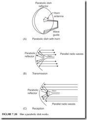
The most effective and widely used microwave antenna is the parabolic dish (see Figure 7.20). This is usually a horn antenna combined with a reflec- tor shaped like a dish. Its shape is a mathematical parabola. Signals transmit- ted by the horn are reflected forward by the parabolic dish shaping the radio waves into a very narrow beam. Received energy is reflected by the dish into the horn antenna. The highly directional nature of the dish gives it a very
narrow beamwidth and enormous gain. These are widely used in satellite TV and radar.
TWO-WAY RADIO
Two-way radio communications between individuals are by far the most wide- spread use of radio. And there are many forms of it. You have seen such radio communications as they take place and you have no doubt engaged in some form of it yourself. In any case, this section takes a look at some of the diverse uses of such two-way communications.
Most two-way radios operate in the VHF and UHF bands. The simplest two-way radios operate on multiple frequencies usually selected by a fre- quency synthesizer. Virtually all two-way radio communications are half duplex, meaning that one party transmits while the other receives.
Aircraft
All airplanes from the smallest single-prop planes to the largest jumbo super jets use two-way radio to communicate with airport towers and the major air traffic management centers across the country. Two-way radio is absolutely essential to the safety of any flight.
Most aircraft radios are transmitters installed in front of the pilot or co-pilot. They usually operate in the 108- to 135-MHz band and use amplitude modulation (AM). Specific channels are assigned for different regions and for different communications functions. The pilot or co-pilot uses front panel switches to select the desired communications frequency. Hand-held micro- phones with a push-to-talk switch are the most commonly used input devices, but other forms of microphones such as throat mikes or microphones attached to headsets are also widely used. Most transceivers operate at very low power and transmission distances are considerable. The height of the airplane gives the radio transceiver an enormous transmission range even with low power at VHF frequencies.
Citizens Band
You have no doubt heard of citizens band (CB) radio and perhaps even used one yourself. Anyone can buy and use a citizens band radio for two-way com- munications. The FCC has allocated 40 frequencies or channels in the 27-MHz frequency range for citizens band operation. The maximum transmission power is restricted to 5 watts, although some hand-held units use less. AM is used.
Citizens band radio has enjoyed wide popularity with individuals and sportsmen as well as truckers. While the advent of the cellular telephone has reduced the number of individuals using citizens band radio, it is still widely used. The primary limitation of most CB radios is the antenna. Since CB radios operate in the 27-MHz range, the required minimum antenna length is approx- imately 9 feet. This can be shrunk somewhat by the use of coils attached to the antenna, but effectiveness is reduced. A CB radio antenna of 5 or 6 feet is common and certainly manageable on a car, truck, or boat. In hand-held trans- ceivers, any antenna longer than about 18 inches is a nuisance.
A 27-MHz frequency allocation of CB radio also gives it some peculiar transmission characteristics. While communications is reliable over short dis- tances of up to several miles, at certain times of the day or evening, worldwide communication is also possible. This is probably more a disadvantage than an advantage, primarily because interference can be received from stations liter- ally anywhere in the world.
Amateur Radio
Amateur or ham radio is a hobby. Technically knowledgeable individuals are licensed by the FCC to use selected frequency bands across the spectrum for
personal communications. Hams use voice as well as CW (continuous wave) or Morse code transmissions. Hams talk to one another about their equipment, the weather, and other common matters. Communication is worldwide and helps to promote good international relationships. Hams frequently design, build, and experiment with their own equipment, although many hams prefer commercially manufactured radios. Hams experiment with digital radios, satellites, and TV.
Family Radio
Family radio is another radio service recently instituted by the FCC for the purpose of short-range personal communications. It supplements CB radio in a wide range of personal communications needs. Because of a different fre- quency allocation, family radios are smaller, more portable, and have more reliable communications over distances of several miles.
All family radios are hand-helds using FM and operating in the 450-MHz range. Only several frequencies in the 450 MHz band are allocated to the Family Radio Service. While many users will share these frequencies, the short communication distances minimize interference between stations using the same frequency. The transceivers are restricted to 2 watts in power. At a fre- quency of 450 MHz, a quarter-wave whip antenna is only about 6 inches long. Communications are extremely reliable up to 1 mile and even farther if transmis- sion takes place outdoors.
You can use family radios in a variety of ways. They are particularly handy when you are camping, hiking, or doing other outdoor activities. Many families use them in shopping malls and even around the house to keep in touch. They are great on farms and ranches and for communications between two nearby cars.
Marine
The very first application of two-way radio in the world was on ships at sea. Ships were always in danger without any form of communication. If a ship was disabled or began sinking, no one would know for a long period of time or maybe never. With a two-way radio or even a one-way radio on a ship, the operator could com- municate with a shore-based radio station to signal danger with the familiar SOS.
Today, a radio is a necessity on virtually every boat and ship. While small boats are not required to carry radios, most larger boats are. And what seaman would be without a radio for safety reasons?
Marine radios have operated on a wide range of frequencies over the years. Ocean-going liners have operated on shortwave frequencies so that long- distance communications are possible. Ships also operate on lower frequencies for exchanging messages and at the higher frequency for reliable communica- tions near land and in port.
The typical marine radio for communicating near ports is a transceiver of 25 to 40 watts of power operating with frequency modulation in the 150- to 170-MHz
range. Most of these units transmit on multiple frequencies, making it always pos- sible to find a clear channel. Channel 16, operating on a frequency of 156.8 MHz, is used for emergency calls. This frequency is typically monitored by other boat- ers and always by the Coast Guard.
Mobile Radio
Mobile radio refers to two-way radios mounted in cars and trucks. These are widely used by police, fire, and other civil services. They are also widely used by taxis, buses, and by companies using fleets of cars or trucks for convenient communications. The typical unit is mounted in the vehicle and provides rela- tively high power in the 25- to 50-watt range. Most communications take place in the 150- to 170-MHz range. Other mobile radio frequency ranges are 450 to 470 MHz. Most radios today are hand-held types.
SATELLITES
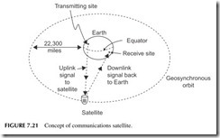
A satellite is a space station that is designed to orbit the Earth and provide a remote radio signal relaying station for the purpose of extending the range of communications worldwide. See Figure 7.21 . Such communications satel- lites contain both a receiver and transmitter that operate simultaneously. The receiver picks up signals from the Earth on one frequency and retransmits them simultaneously on another frequency. In this way, the transmitter and receiver in the satellite do not interfere with one another.
Most communications satellites are geosynchronous. These are satellites positioned to orbit directly around the Earth’s equator at a distance of 22,300 miles from Earth. When located in this position, the satellite rotates in exact synchronization with the Earth’s rotation. Thus, the term geosynchronous. Because the satellite and the Earth are rotating together, it appears as though
the satellite is stationary overhead to an observer on Earth. With the satellite in a fixed position with respect to the Earth, the satellite becomes a near-perfect radio repeater station.
Figure 7.22 shows a general block diagram of a satellite. The communica- tions part of a satellite consists of a combined receiver and transmitter called a transponder. Satellites operate in the microwave region. The C band from 4 to 6 GHz and the Ku band from 11 to 18 GHz are the most popular operating ranges. A low-noise amplifier (LNA) picks up the very small 6 GHz uplink sig- nal from Earth. It is mixed with a 2-GHz LO signal and down-converted to a 4-GHz downlink signal, which is then amplified by a high-power amplifier (HPA) and retransmitted back to Earth. Most satellites contain many transpond- ers with wide bandwidth capable of handling many signals simultaneously.
The satellite power source is batteries combined with a system of solar cells. The solar cells convert light from the Sun into electrical energy that is used to recharge the batteries. This system gives the satellite long life in space. Communications satellites are used primarily in long-distance telephone communications and for distribution of TV signals. Some satellites are used for navigation, a good example being the global positioning system (GPS) widely used by the military and commercial organizations. It is also widely used by individuals as they find their way with personal navigation devices (PNDs) like those from Garmin and Tom Tom. The GPS system uses 26 satel- lites about 10,800 miles above the Earth orbiting in overlapping patterns so that at least three of four are “visible” by wireless at any point on the Earth.
Other satellites are used for surveillance. Spy satellites only 102 miles high pick up radio signals as well as infrared images and photographs. Weather sat- ellites monitor cloud formations and movements. There are also two satellite telephone networks with low-Earth-orbit satellites to permit communications to/from any point on the planet.
RADIO TELESCOPES
Observation of the planets and stars is usually done with an optical telescope. However, in 1932 researchers discovered that distant stars or suns emit- ted radio waves. All stars, like our Sun, emit radio frequencies. Most of this energy occurs in the microwave region at 1.4218 GHz. This is the frequency of ionized hydrogen. By building a highly sensitive radio receiver and coupling it to a large highly directional radio antenna, it is possible to plot the position of distant stars just as effectively as an optical telescope. Radio telescopes are, in fact, even more effective in that they can more easily detect distant stars that cannot be seen even by the best optical telescopes.
Radio astronomy observatories consist of an enormous parabolic dish antenna usually 60 to 250 feet in diameter, which can be rotated and tilted so that it scans the skies. An array of multiple smaller dishes can also be used as in the SETI (search for extraterrestrial intelligence) project in New Mexico. The antennas are coupled to one or more very sensitive radio receivers. These
receivers have very high gain so that they can sufficiently amplify very small signals received from stars that are many light years away. Often special cool- ing systems are used to reduce the temperature of the receiver front end to minimize noise, thereby permitting even weaker signals to be received. The largest radio telescope is a parabolic dish reflector built of screen mesh 1000 feet in diameter. The dish is built into the valley between adjacent mountains near Arecibo, Puerto Rico. The horn antenna is moveable on a long cable so it can be positioned to see any part of the sky.
Wireless Everything
It seems like everything is going wireless these days. Cordless telephones, wireless local area networks, and your TV remote control. But wireless has always been around just not by that name. Most radio applications are old and well known. A few examples you may have encountered follow.
Garage door opener. A tiny transmitter in your car transmits a binary coded message to the receiver in your garage hooked up to the door motor.
Remote keyless entry. A miniature transmitter on your key ring transmits a sig- nal to a receiver in your car that opens the door locks. Some even turn on lights and start your car from 10 to 30 feet away.
Wireless data acquisition. Remote transmitters are set up with solar batteries at remote sites to gather data from sensors and transmit it back to a collection center. A good example is electric, gas, and water utilities that use such systems to moni- tor critical conditions at remote sites and transmit the data back to a central moni- toring facility where decisions can be made. Home wireless thermometers are very common.
Radio control of models. This is very common in toy cars, model airplanes, and boats.
RFID. Ultra miniature radios are being embedded in shipping labels, cars, and other objects for identification purposes. The units transmit their unique ID code when scanned by a nearby receiver.
HD radio. This is digital radio broadcasting in the United States. Most U.S. AM and FM stations now transmit a digital version of their signals on the same fre- quencies as their analog transmissions. They use a form of digital modulation called OFDM (see Chapter 8). It produces greater frequency response than the regular analog broadcasts, making AM sound more like FM and FM sound more like a CD. A special radio is needed to receive it. The digital technology makes noise and fading less of a problem. And it permits each station to add several additional channels thanks to the multiplexing capabilities of the HD technology. Security tag.sThe plastic tags clipped on new clothes to prevent their being stolen contain a tiny antenna and electronic circuit that make their presence known at a nearby transmitter/receiver unit.
Surveillance and bugging, or secret monitoring or electronic spying. This is not just something you see in the movies or on TV. It is more widely used in private investigation, police work, and industrial espionage than you may think. Scary. Face it, wireless is truly everywhere.
Project 7.1
Investigate HD Radio
HD radio is digital radio in the United States that shares the same frequencies as the regular AM and FM bands. You can buy stand-alone HD receivers, and some stereo receivers include it. HD radio is also available in some cars. To learn more about this technology, go to the website of the developer iBiquity or www.ibiquity.com. Also try a Google/Bing/Yahoo search on HD radio.
Project 7.2
Become Familiar with ISM Radio
ISM radio is the term used to refer to short-range data radios used in the FCC’s unlicensed spectrum designated for industrial-scientific-medical (ISM) applica- tions. Got to the FCC website www.fcc.gov and find the most commonly used ISM frequencies of operation in Part 15 of the rules and regulations. Do a general search of ISM to determine some common applications.
Project 7.3
Radar
Radar (radio detection and ranging) is a type of wireless. It has many uses, mainly military but also commercial and civilian. Marine and aircraft navigation are key applications. Police radar is widely used. Radar is also showing up in automobiles as detectors of distance between vehicles for automatic braking. You may wish to learn more about this technology. Do a search on radar.
Project 7.4
Shortwave Radio
Buy a low-cost shortwave radio and experience listening to international broad- casts and amateur radio operation.
Project 7.5
Experience CB or FRS
Go to your local Radio Shack and buy a pair of Family Radio Service walkie-talk- ies. Then test them to determine maximum range. As an alternative, buy a CB radio and listen to what is going on with the truckers or other locals.
