Video Technology
TV and Video Is All Digital Now
In this Chapter:
● How scanning works to create video.
● Basic color TV principles.
● U.S. and other standards for digital and high-definition TV.
● How a digital TV set works.
● TV screen technologies.
● Cable TV.
● Satellite TV.
● Cell phone TV.
● DVD players.
INTRODUCTION
Nothing in electronics has affected us more than the development of television. Okay, I haven’t forgotten the PC and the Internet, which have also seriously impacted our lives. But TV came first and has been working its magic on us for far longer. The impact of television or video on our lives is signifi- cant in that we spend more than half our waking hours in front of a TV screen, either watching TV or working with a video monitor on a computer. The social and political impact has been enormous. And, of course, you also interact with the liquid crystal display (LCD) screens on cell phones, laptops, and personal navigation devices. For this reason it helps to understand a little bit about how video works. Video is perhaps one of the most complex segments of electron- ics, but this chapter makes those fundamentals easy to understand.
VIDEO FUNDAMENTALS FOR THE IMPATIENT
The main feature of any video device is the screen. The first video or TV screens were cathode ray tubes (CRT) and those are still used in older TV sets and com- puter monitors. The most commonly used TV and video screen today is the LCD. LCD screens are used in the newer TV sets and in most personal computers.
They are also used in laptops, netbooks, cell phones, personal navigation devices, and anything else that has a screen on it. TV sets also use plasma, dig- ital light-processing (DLP) projection technology, and other methods to display very large pictures. There is more detail on TV screens later in this chapter, but for now, the most important part of understanding video is to learn the method- ology used to create and present video regardless of the screen type.
A video system is a method for converting a picture or scene into an elec- tronic signal that can be transmitted by radio or cable or stored electronically. Some type of device is needed to take in the light and color information from a picture or scene and convert it into an electrical signal. Once in electrical form, the video can be modulated onto a radio carrier for transmission or electroni- cally stored. The process of converting the scene or picture into an electrical signal is known as scanning.
Scanning Fundamentals
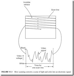
A video signal is usually generated by a video camera. The camera takes the scene and scans it electronically, dividing it into hundreds or even thousands of very thin horizontal lines (see Figure 11.1).
The horizontal scan lines comprise a sequence of light and color variations. The camera produces an analog signal whose frequency and amplitude vary with the brightness and color changes along the scan line. The whole idea in video is to transmit the video signal one scan line at a time at very high speeds. If you are not transmitting the signal by radio or cable, you can store it, such as recording it on magnetic tape. In any case, the received signals are then converted back into scan lines and applied to the screen by scanning the lines across the receiving screen very fast from left to right and top to bottom.
The secret to producing a high-quality video picture is to use enough scan lines with enough detail in each so that the color, brightness, and fine detail in the picture are retained. Note in Figure 11.1 that the analog signal for one scanned line is such that the higher-amplitude voltages are closer to black while the lower-amplitude signals are closer to the white level. This is what a scan line from a monochrome or black and white (B&W) video system pro- duces. It is called the brightness or Y signal. Color will be covered later.
Aspect Ratio
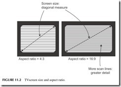
When talking about TV screens, the key factors are size and aspect ratio. The sizeis usually the diagonal measure of the screen in inches. The aspect ratio is the ratio of the picture width to the picture height. Standard TV sets and video monitors use an aspect ratio of 4:3 as shown in Figure 11.2 . Most of the newer TV screens and video monitors have an aspect ratio of 16:9. This wider format was chosen because it is a better fit with the wide-screen movie formats used by Hollywood.
Persistence of Vision
When you think about it, it just doesn’t seem possible that a complete picture or scene can be reproduced in electronic format by scanning. The scanning process just breaks the picture or scene down into hundreds or perhaps thou- sands of scan-line signals, and the only way that a picture can be created is for those scan lines to occur at a very high rate of speed. Luckily, this technique works because we all have a visual characteristic known as persistence of vision. Persistence is that characteristic of the eye which prevents it from fol- lowing very high-speed changes in light variations. In other words, if the scan lines are traced across the screen at a very high rate of speed, your eye simply cannot follow them one at a time but instead puts the whole thing together and sees a single steady picture. If you scan at too low a rate, you will actually begin to see the scan lines and your eye will interpret this as a kind of flicker.
The concept of persistence of vision has been known for decades. Motion picture films take advantage of this characteristic of our eyes as well. Remember that movies are just a high-speed sequence of individual still pictures recorded on film. If you can get the frame rate up to a level of approx- imately 24 frames per second or faster, your eye will translate the changes from one still frame to the next as motion.
Analog TV
As you probably know, the Federal Communications Commission eliminated analog TV broadcasts in the United States as of June 12, 2009. But while ana- log TV has been replaced by digital TV, that doesn’t mean that it isn’t still around. You will still find analog TV in many other countries of the world, and it is also still widely used in closed-circuit television. In any case, it is such a widely used standard that understanding it is useful.
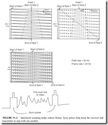
Back in the late 1940s and early 1950s, the United States created what is called the National Television Standards Committee (NTSC) TV standard. It basically specifies that a picture is made up of 525 horizontal scan lines, known as a video frame. As it turns out, one frame is actually made up of two fields of 262.5 scan lines. The scene or picture is first scanned 262.5 times from top to bottom, creating one field. This field is then transmitted at a rate of 60 fields per second. Then the scene is scanned again with another 262.5 lines and these are transmitted next. The second field is interlaced with the first field to form the complete 525 line picture. See Figure 11.3 . The result is that you will see 30 complete 525-line frames per second. This is fast enough for per- sistence of vision to work nicely. The interlacing helps significantly in reduc- ing any perceived flicker.
One thing that you may be wondering is how do you keep the TV receiver screen in step with the video camera or other video source? This is solved by creating synchronizing pulses that are transmitted before and after each scan line (see Figure 11.3). After one field is scanned, a larger group of synchronizing pulses occurs between fields to cause the receiver to start the scanning back at the top again. The synchronizing pulses are transmitted or stored along with the analog video signal for each line. These synchronizing pulses are then used to trigger the receiver’s circuitry to make sure that the scene is sequenced prop- erly on the screen.
Other World TV Systems
The U.S. NTSC analog system is used in Canada, Mexico, and Japan. But other analog systems are used throughout the world. In Europe, specifically the UK, Germany, Italy, and Spain, the PAL (phase alternation line) standard is used. It uses 625 scan lines with a frame rate of 25 frames per second. In France and in some other countries, a system called SECAM for Sequenteil Couleur a Memorie (or sequential chrominance and memory) is used. It too uses 625 scan lines and a 25-frame-per-second rate. PAL and SECAM systems have a better vertical resolu- tion for picture detail because of the greater number of scan lines, giving a per- ceptibly improved picture over the NTSC system. Most of the other countries of the world have adopted one of these three systems.
Digital TV
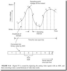
Most TV and video now is transmitted and stored in digital or binary format. Scanning is still the process used to convert the scene into an electrical signal, in this case a stream of binary numbers representing the brightness and color detail. Each scan line is still essentially an analog signal but that is converted into a sequence of binary numbers by an analog-to-digital converter (ADC). The basic process is illustrated in Figure 11.4 . The ADC samples are measures of the analog signal at a constant rate, as shown by the dots along the curve
in Figure 11.4. Remember that in order to retain the information in an analog signal when it is converted into digital, the signal must be sampled at a rate at least twice as fast as the highest-frequency signal contained in the analog sig- nal. Since video signals contain extremely high frequencies, the sampling rate is very fast. Most video contains scene details with frequencies beyond 4 MHz. That means a sampling rate of at least 8 MHz to capture the detail. In any case, each sample results in an 8-bit binary number. These bytes, one representing each of the sequential samples, are sent one after another in a serial binary data stream as shown. The video data can then be transmitted or stored.
Each of the binary numbers produced by sampling produces what we call a pixel or picture element. This particular binary number will ultimately translate to a specific analog voltage value and produce a specific brightness level along the scan line.
One way to visualize a digital video display is to think of it as an array, or horizontal scan lines, each made up of a sequence of pixels (see Figure 11.5). Each pixel is a dot of light or, in this case, a square. That pixel is derived from a specific binary number developed during the scanning and sampling process. Each of those pixels represents a specific brightness level from white to black. A digital-to-analog converter (DAC) converts the binary brightness value back into a specific shade of gray.
Digital TV (DTV) uses the interlaced scanning principles described ear- lier to help minimize flicker. But it also uses a faster progressive scan. This is where each scan line making up the screen is scanned sequentially one after the other from top to bottom. To minimize flicker, progressive scanning must be done at a higher rate of speed than interlace scanning. Progressive scanning
is used simply because it creates a sequence of digital numbers that is more conveniently stored and processed one after the other than in a two-step inter- laced process.
DTV uses a variety of different formats. In the basic format, it produces 480 scan lines with 640 pixels per line. This is roughly the equivalent of what you would see with an analog TV signal. This is what we call the DTV standard- resolution format. Both interlaced and progressive scanning formats can be used with rates of 24, 30, and 60 frames per second.
Picture Resolution
One thing that you should understand about video is the concept of resolution. This refers to how much fine detail you can see on the screen. In analog TV, brightness and color detail results in very-high-frequency analog signals. The older original analog TV was limited to frequencies of approximately 4.2 MHz. Modern HDTV uses much higher-frequency responses up to about 10 MHz. To see that picture detail, you must transmit the analog signal over a channel that has suf- ficient bandwidth. Most radio channels and cable systems have bandwidth limita- tions, and essentially act as a low-pass filter that will remove some of the higher frequencies. While you will still see a picture, it will lack some of the fine detail that your eye may or may not notice.
Resolution as it relates to DTV is a combination of how many scan lines plus how many pixels per line are used. Obviously, the greater the number of scan lines and the greater the number of pixels, the more detail you are going to be able to transmit and ultimately see.
A higher-resolution format to produce what we call high-definition (HD) TV uses 720 scan lines with 1280 pixels per line. The ultimate high-definition format uses 1080 horizontal lines with 1920 pixels per line. Both of those high- definition formats can use either interlace or progressive scanning at rates of 30, 60, 120, and 240 frames per second. Just remember that the frame rate sim- ply refers to the number of times per second that each frame is presented on the screen. The earlier slow frame rates of 30 and 60 frames per second often produces a kind of picture smearing when the scenes are changing at a high rate of speed. This is noticeable in action movies or in sports events. The newer 120- and 240-frames-per-second scan rates essentially eliminate this problem.
Color Video Principles
Thus far, the signals we have described are what we call monochrome or black-and-white video. In monochrome video, all we capture and transmit and reproduce is the brightness variations along a scan line that range from black to white and an infinite number of shades of gray in between. But, of course,
today most video is color. Capturing, transmitting, processing, and displaying color is a far more complex process than monochrome.
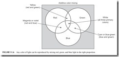
One physics principle that makes color video possible is the concept that any color of light can be reproduced by simply mixing the right combination of red, green, and blue light. Take a look at Figure 11.6 . Mixing red and green creates yellow. Mixing red and blue produces violet (magenta), while mixing green and blue produces the color cyan. In any case, as it turns out virtually any color can be created using just the right mix and intensities of red, green, and blue. Strangely enough, there is one unique combination of the three colors that creates white. Black is produced, of course, by just turning off all the light sources. The color TV problem is how do you capture the individual colors and then how do you reproduce them?
Most video cameras use a light-sensitive imaging chip called a charge- coupled device (CCD). An optical lens focuses the scene on the chip. The chip itself is made up of millions of tiny light-sensitive elements that are charged like a capacitor with a voltage depending on the brightness level reaching them. The analog video signal for a scan line is then created by sampling those light- sensitive elements one at a time horizontally. The result is an analog signal whose amplitude is proportional to the light level. The result is a black-and- white brightness or Y signal.
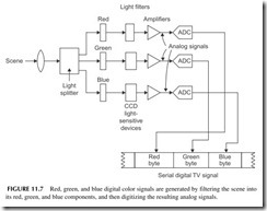
Figure 11.7 shows how the color signals are produced. The scene is actu- ally passed through a lens and a beam splitter that divides the scene into three identical segments. Each is passed through individual red, green, and blue fil- ters. Three light-sensitive imaging chips (CCDs) then produce three separate analog signals for the red, green, and blue elements in a scene. The red, green, and blue analog signals are then individually amplified and sampled by an ana- log-to-digital converter (ADC) to translate them into a binary sequence. The three binary streams are then transmitted serially as a sequence of red, green, and blue for each picture element on the imaging chip. Each of these RGB colors will then later form a pixel on the viewing screen.
Video Compression
Generating a color video signal produces a serial bitstream that varies at a rate of hundreds of millions of bits per second. Consider these calculations:
● For each pixel, there are three color signals of 8 bits each making a total of 8 X 3 = 24 bits per pixel.
● For a standard DTV screen, there are 480 lines of 640 pixels for a total of 307,200 pixels per frame or screen.
● For one full screen or frame, there are 307,200 X 24 = 7,372,800 bits.
● If we want to display 60 frames per second, then the transmission rate is 7,372,800 X 60 = 442,368,000 bits per second, or 442.368 Mbps. That is extremely high frequency.
● To store one frame of video of this format, you would need a memory with 55,296,000 bytes or 55.296 MB. And that is just one frame.
● To store 1 minute of video you would need a memory of 3,317,760,000 bytes or just over 3.3 gigabytes (GB). And that is just 1 minute. Multiply by 60 to get the amount of memory for an hour.
Imagine the speeds and memory requirements for 1080p or a 120 frames- per-second format. And we have not even factored in the stereo audio digital signals that go along with this. Anyway, you are probably getting the picture here. First, data rates of 442.368 Mbps are not impossible, but they are imprac- tical as they require too much bandwidth over the air and on a cable. And they are expensive. Furthermore, while memory devices like CDs and DVDs are available to store huge amounts of data, they are still not capable of those fig- ures. Therefore, when it comes to transmitting and storing digital video infor- mation, some technique must be used to reduce the speed of that digital signal and the amount of data that it produces.
This problem is handled by a digital technique known as compression. Digital compression is essentially a mathematical algorithm that takes the individual color pixel binary numbers and processes them in such a way as to reduce the total number of bits representing the color information. The whole compression process is way beyond the scope of this book, but suffice it to say that it is a technique that works well and produces a bitstream at a much lower rate. And, the compressed video will take up less storage in a computer memory chip.
The digital compression technique used in digital TV is known as MPEG-2. MPEG refers to the Motion Picture Experts Group, an organization that devel- ops video compression and other video standards.
What you have to think about when you consider the transmission of digital video from one place to another is that it is typically accompanied by audio. The audio is also in serial digital format. Those digital words will be transmit- ted along with the video digital words to create a complete TV signal.
TV Transmission
The compressed audio and video of a TV signal are assembled into packets or frames that look like that in Figure 11.8. The 4 bytes up front provide synchro- nizing bits for the receiver. The ID header tells the packet number, sequence, and video format used. The remaining bits are the serial compressed video and audio.
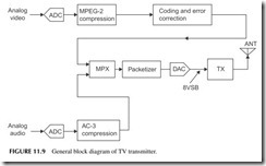
Figure 11.9 shows a simplified TV transmitter. The serial digital video is put through the MPEG-2 compression process. This is followed by additional
bit manipulation and coding for error correction and improved signal recov- ery by the receiver. This serial data is then multiplexed with the serial com- pressed audio data. Then the packets are formed. This is what will modulate the transmitter.
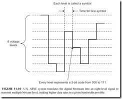
The modulation begins by translating the fast serial bitstream into an eight- level signal with a DAC. Each 3-bit segment of the serial data is assigned a specific voltage level as shown in Figure 11.10. Since each level represents 3 bits, you can transmit more bits per second in the same time period. It is this eight-level signal that modulates the transmitter carrier. The modulation is AM, where all of the upper sidebands are transmitted but only part of the lower sidebands. This saves spectrum. The modulation is referred to as 8VSB for vestigial sideband, where vestigial refers to part of the lower sideband. The signal is then up-converted to the final frequency by a mixer. A high-power amplifier in the transmitter sends the signal via coax cable to the antenna. Typical TV station range is about 70 miles maximum, and that is determined by tower height and terrain.
In the United States, each TV channel is 6 MHz wide. There are 50 channels starting at channel 2 from 54 to 60 MHz. Channels 3 through 6 range from 60 to 88 MHz. Channels 7 through 13 run from 174 to 216 MHz. Channels 14 through 51 run from 470 MHz and ending with channel 51 from 692 to 698 MHz.
TV Receiver
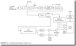
Figure 11.11 shows a general block diagram of a modern digital TV receiver. The signal from the antenna or cable TV box is sent to the tuner where the signal is amplified and sent to a mixer along with a local oscillator signal to down-convert the signal to a lower frequency called the intermediate fre- quency. This is commonly 44 MHz. The local oscillator is a frequency syn- thesizer that selects the desired channel, usually with a remote control. The IF signal is filtered to select only the desired 6-MHz channel.
The IF is then sent to an ADC for digitizing. The 8VSB signal is then recovered in the demodulator. It is then translated into the original bitstream, and any coding or error correction is removed. The signal is then demul- tiplexed into the video and audio streams. The video goes to an MPEG-2 decompression circuit for recovery of the original video. The individual RGB components are sent to DACs to recover the picture detail. The RGB signals are then amplified and sent to the screen for display. The audio is also decom- pressed and sent to the DACs and amplifiers and speakers.
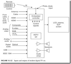
The whole TV set looks something like Figure 11.12. Note all the possible inputs. The set gets its RF inputs from the antenna or cable box. The cable box may also have a digital signal output, meaning the cable box does all the decod- ing, demultiplexing, and decompression. The output comprises a serial data stream of the video and audio. A special high-speed digital interface called the high-definition media interface(HDMI) is used. It uses a special cable no more than 15 feet long and with a special 19-pin connector. The HDMI carries video and audio from the TV to cable box or DVD player or vice versa.
Most TV sets also accept analog video inputs from other sources like VCRs, video cameras, and digital cameras. A special fiber optic cable input called TOSLINK serves as the interface for TV sets, cable boxes, and DVD players.
Finally, some TV sets include standard computer interfaces like USB ports or the IEEE 1394 interface, a fast digital serial interface for video and audio developed by Apple.
TV set outputs, of course, are sent to the screen and the speakers. A remote control sends signals to an embedded controller that tells the set what to do.
TV Screen Technology
As indicated earlier, there are several ways that the video signal is translated back into a viewable picture. The cathode ray tube is still present in older sets, but LCD screens are by far the most popular and most widely used today. Plasma screens are still available but slowly fading away, and DLP projection screens are popular because of their low cost. There are other emerging tech- nologies that we may see in the future. In any case, what we need is a light source to reproduce the varying intensities of red, green, and blue light.
Color video screens are made up of a very large number of tiny red, green, and blue light sources. These are used to make up the pixels or dots of light
that re-create the picture. These pixels are very small, so that your eye cannot actually see them even when you are relatively close to the screen.
Figure 11.13 shows some of the screen pixel formats in use today. Cathode ray tubes were made up of a group of three color phosphor as shown in Figure 11.13A. These color triads were grouped tightly together to form the complete screen. When an electron beam strikes each of the red (R), blue (B), and green (G) pixels, they cause the phosphor dots to glow. The eye automatically mixes the individual red, blue, and green colors to reproduce the desired color.
LCD and plasma screens use a pixel format somewhat like that shown in Figure 11.13B. These are usually rectangular red, green, and blue areas that are backlighted with the appropriate degree of intensity.
One pixel is not necessarily equal to the three color group shown in Figure 11.13A. Instead, 1 pixel as displayed on the screen might actually be made up of a collection of these individual groups. The actual pixel size may be something like Figure 11.13B, made up of multiple groupings of red, blue, and green elements as shown.
The actual format displayed on the screen is determined by the TV dis- play standards. As indicated earlier, a standard DTV screen uses 480 horizon- tal lines with 640 pixels per line. That creates a screen with a total of 307,200 pixels. The 720 X 1280 screen puts 1280 pixels on 720 lines for a total of
921,600 pixels. The big daddy of all screens uses 1080 lines with 1920 pixels per line for a total of 2,073,600 pixels. Just remember that the pixels are turned on one at a time from left to right and top to bottom on the screen at a very high rate of speed.
Summary of Screen Technologies
The actual technical details of each of the different types of screens are way beyond the scope of this book, but a summary might be useful. A quickie review of each of these screen types follows.
CRT—A cathode ray tube contains three electron-beam guns, each one driven by the analog color signals from the DACs. The intensity of the electron beam depends on the intensity of the light and color signal being fed to it. These electron beams are aligned so that they strike the red, green, and blue phosphor dots covering the screen. Each dot emits light with an intensity pro- portional to the strength of the electron beam striking it. The electron beams are scanned simultaneously across the screen at very high speed, stimulating the pixels in the right proportion to reproduce the desired color.
LCD —Liquid crystals are, as their name implies, a liquid made up of mol- ecules whose physical orientation can be changed by the application of an elec- tric signal. Different voltages change the polarization of the light through the liquid. By applying one level of voltage to the liquid crystal, it can be made almost totally transparent where maximum light passes through it. Another level of voltage will twist the molecules and practically block all light from being passed. In this way, the liquid crystal acts almost like a camera shutter but in this case with varying degrees of transparency being possible. The liquid crystal material is contained within glass plates. A bright light source such as a fluorescent lamp or high-brightness LEDs are placed behind the liquid crystal.
In front of the liquid crystal is another transparent sheet containing the red, blue, and green pixels described earlier. The whole thing is sandwiched together in a very thin screen. The electrical signals applied to a matrix of wires cause the liquid crystals to be properly oriented for each pixel and to allow the correct proportion of light through to each of the red, blue, and green light filters.
Plasma—A plasma screen is also made up of many tiny light sources. Each light source or subpixel is actually a small chamber containing xenon and neon gases. When a voltage is applied to each of these chambers, the gases ionize and emit ultraviolet light. The ultraviolet light then actually strikes a phosphor coated inside the chamber. The chamber then emits red, green, or blue light. The degree of ionization determines the brightness of each subpixel. In any case, electrical signals are then applied in sequence to the subpixels to turn them on with the correct degree of brightness to produce the desired color.
DLP—Digital light processing is a technique invented by Texas Instruments. The heart of it is an integrated circuit chip made up of hundreds of thousands or millions of tiny mirrors. The mirrors can be moved to one of two positions. This is an example of a microelectromechanical system (MEMS). MEMS is a tech- nique for making mechanical moving objects using semiconductor manufactur- ing techniques.
Each of the tiny mirrors can be moved so that in one position it will reflect maximum light (representing white) and the other position where no light is reflected (representing black). You can then produce any shade of gray simply by switching the individual mirrors off and on at a high rate of speed. The light source is shined on the mirror and the resulting monochrome scene produced on the DLP chip is then focused on a screen from the rear by a lens system.
To produce color, the light source is passed through a rotating disc with alter- nating red, green, and blue segments. The speed of rotation and the frequency of each color on the disc allow each mirror to then reflect a specific color of light. In the newer DLP screens, high-intensity red, green, and blue LEDs are used to send light to the mirrors, which are then mixed and projected onto the screen.
LED —The newest TV screens are made of tiny red, green, and blue light emitting diodes arranged in a pixel matrix as described earlier. The LED screens are the brightest available and respond fast to action scenes. However, they are the most expensive screens.
3D TV
Yes, you actually can buy a 3D TV set that gives you that same 3D “coming- at-you” feeling of theater 3D. As this is written, these sets are very expensive and there is very little 3D material to see. Right now it is only available on DVD. Eventually it may be available by cable or satellite or over the Internet. And, yes, you still have to wear the special glasses. These glasses are not the red and green lens type but a special electronic version. The lenses use elec- trical polarization like a shutter that turns the left and right lenses off and on in synchronization with the two alternating sets of frames on the screen. A wireless signal (IR or radio) signals the glasses when to switch. The switching occurs at very high speed so the effect is to see the 3D scene. Only time will tell if this is just a gimmick or niche TV product.
Which Screen Type Is Best?
It is very difficult to find a new TV set with a CRT. You can still buy them, but they are typically only available in the smaller screen sizes such as 9, 13, and 19 inches.
LCD screens are available in a wide range of sizes, but the minimum today for a TV set is about 19 inches. Remember that these dimensions are the diago- nal dimension from an upper corner of the screen to the lower diagonal corner. The most popular LCD screen size is 32 inches, but they are available in a wide range of sizes from about 42 to 65 inches. Even bigger ones are available. Plasma screens come in sizes from about 42 inches to about 70 inches. A DLP screen can be had in sizes from 50 to 100 inches.
As for prices, LCD and plasma screens are approximately comparable. DLP projection screens are significantly less expensive for the same size.
There are a couple of other factors to consider in evaluating screen types. As far as brightness goes, they are all very good, with the DLP probably slightly less bright than the other two types. Contrast, meaning the ratio of the brightest white to the darkest black, is also excellent on all types of screens, a little bit less so on the LCD.
Viewing angle means whether you can see the picture from any angle. Most screens are viewed directly straight on, but many viewers are off to the side or at an angle. DLP screens generally have poor viewing angles: when you get too far off to the side, you will not be able to see the picture or it will fade away. LCDs have this problem but to a lesser extent. Plasma screens have the widest viewing angles.
Finally, the ability of a screen to produce high-speed motion is generally excel- lent on plasma and DLP screens. LCDs did produce some smearing, but recently the higher scan rates of 120 and 240 frames per second have essentially elimi- nated this problem.
LCD screens dominate TV today and are gradually replacing all other types as their price continues to drop with better manufacturing methods. Plasmas and DLP are still available but are gradually fading. LED screens are growing in popu- larity and will become more widely used as prices come down in the future.
CABLE TELEVISION
It is estimated that about 15% of all U.S. citizens get their TV over the air with an antenna. But over 70% get TV via cable. The remaining 15% get satellite TV. Why? Mainly because cable offers not only better, more reliable signals than by antenna, but also offers hundreds of channels of programming. But that’s not all. Most of those who have cable also use the cable connection for
high-speed Internet access service. Of course, you pay for all that, and it has become like a monthly utility bill. With the cable industry being so big, it pays to know a little more about it.
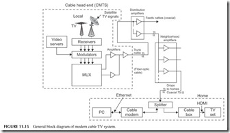
It all starts with a facility called the cable head end. Another name you might hear is cable modem termination system (CMTS), which specifically is the equipment at the head end. This is a place where the company collects video and programming from many different sources. It snatches signals off the air, it receives premium programming like HBO, ESPN, Showtime, and Fox via satel- lites, stores movies on its large computers called video servers, and may even do some of its own local programming. The result is a hundred channels or more.
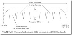
Now each of those TV signals—video plus audio—is modulated onto car- riers that are spaced 6 MHz apart just like the regular over-the-air TV channels. Then all of those modulated carriers are added together to form a very com- plex signal. That signal is then amplified and put on the outgoing cable. Figure
11.14 shows what the spectrum looks like. Most cables have a bandwidth from about 50 MHz up to about 860 MHz to 1 GHz, which will accommodate up to about 130 6-MHz channels. We call this process frequency-division multiplex- ing, where a single cable can carry many separate channels of data, each on a different frequency and bandwidth. And since the cable is shielded, it does not radiate, so it, in effect, duplicates the free-space electromagnetic spectrum.
Since most TV today is digital, digital modulation methods are used to put multiple TV signals within each 6-MHz channel. Using 16-QAM or 64-QAM, a cable company can squeeze several channels of video/audio into each 6-MHz chunk of spectrum, providing hundreds of additional slots for programming. That is why cable companies can advertise up to 500 channels of entertain- ment, news, and so on.
All of the digital video/audio signals are then remodulated onto differ- ent channel assignments. All of these 6-MHz channels are added together or linearly mixed in a multiplexer (MUX) to create a massively complex compos- ite signal. This is what goes out on the cable (see Figure 11.15).
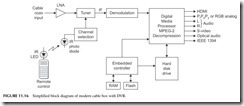
The signal distribution network is called a hybrid fiber cable (HFC) system. This multiplexed signal is applied to a fiber optic cable, called a trunk cable. It is routed around the city and it terminates at selected points where the signal is divided into multiple paths of coax cable. These so-called feeder cables are connected to amplifiers along the way to overcome the large attenuation of the cables. At some point, the feeder cables come into your neighborhood and are further amplified and split into multiple signals. These signals are then sent to your house by a coax drop cable. The most common type is 75-ohm RG-6/U coax with F-connectors. The cable comes into your home and is usually split two or more times and sent to wall connectors in the various rooms. These connectors connect the signal to a cable box and/or a cable modem for the PC. The cable box is like a tuner in that its main job is to select one of the many channels and send it to your TV set. Figure 11.16 shows a simplified block diagram of a typical cable box, usually called a set-top box (STB). The input is a TV tuner with channel selection via a frequency-synthesizer local oscillator by way of your remote control. The selected signal is then demodulated and decompressed by a digital media processor chip, and then sent to the TV set via one of the many possible interfaces, usually the HDMI or high-definition multi- media interface. This is a very fast digital interface with special cable and con- nector. Most TV sets have this as the most common input. Other video format interfaces such as RGB, PrPbPy, or S-video, are usually provided to accommo- date older analog TV sets. An additional feature of many of the newer STBs is a built-in digital video recorder (DVR). This is essentially a computer hard discdrive that records the program you want to save for viewing later.
Other Wired TV Distribution Systems
There are a couple of other ways that digital video is distributed to homes. One is a fully fiber optic system. The fiber cables go all the way from the head end to the homes. This was once too expensive, but today, thanks to improved fiber and other technologies, it is cost effective. Such systems are generally referred to as passive optical networks (PONs). “Passive” simply means that the signals are strong enough and the cable runs short enough so that no amplification is needed along the way. The digital video and audio are modulated onto infrared (IR) light beams and sent down the cable. Because fiber has such wide bandwidth, data rates are extremely high, over 1 GB/second in the newer systems. This allows not only digital video to be transmitted but also very-high-speed Internet service. Such systems use standards like Ethernet PON or GPON for gigabit PON. A typical U.S. system is Verizon’s FiOS.
Another new system is called IPTV for Internet protocol TV . This is video dis- tribution via putting the compressed video on a fiber optic cable using the famil- iar TCP/IP protocols. The signals travel via fiber to the neighborhoods. From there they are split off and the signals travel via in-place twisted-pair telephone lines.
Other Wired TV Distribution Systems (Continued)
New forms of modems using a form of OFDM called discrete multitone (DMT) transmit the signal over the twisted pair at high speeds. These lines are now used just for high-speed Internet service and are referred to as asynchronous digital subscriber lines (ADSL or just DSL). Newer versions called ADSL2 and ADSL2+ or VDSL for video DSL provide data rates from 26 to 52 Mbps on standard phone lines. An example of a system in the United States is AT&T’s U-verse system.
For Internet access, you connect a cable modem to the coax cable and it automatically selects the channel where the data services are assigned. The modem goes to your computer via an Ethernet cable. Access to the Internet is by way of your computer’s browser.
SATELLITE TV
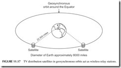
Satellite TV technically is also over-the-air TV or radio, but instead of the sig- nals coming from one or more local TV stations, broadcast towers, the signals emanate from a geosynchronous satellite 22,300 miles away orbiting around the Equator (see Figure 11.17 ). The satellite transponders operate in the Ku band with frequencies of 10.95 to 14.5 GHz. This system is referred to as direct broadcast satellite (DBS).
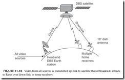
The satellite TV company gets its TV like the cable companies, and brings it all together at a single Earth station head end where it is all collected and transmitted on an up-link to the satellite in the 14- to 14.5-GHz range (see Figure 11.18). The signals are then amplified in the satellite and rebroadcast on the down-link frequencies at 10.95 to 12.75 GHz. A high-gain antenna focuses the signals on the United States or other country of interest.
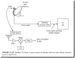
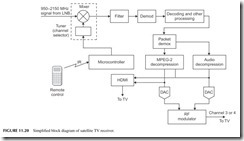
Down on Earth, satellite TV subscribers have a special receiver and antenna. These are illustrated in Figure 11.19 . The antenna is usually a small dish or parabolic reflector antenna about 18 inches in diameter. The antenna is usually a small horn. Also inside the antenna assembly is a low-noise amplifier (LNA) to boost the small signal from the satellite. This is then sent to a mixer along with a local oscillator signal to down-convert the signals into the 950- to 2100-MHz range. This signal is then routed by coax to the satellite receiver. The LNA/mixer assembly at the antenna is called a low-noise block (LNB) converter. This receiver signal processing at the antenna is necessary because the Ku band frequencies of 10.95 to 12.75 GHz are so high they would be far too greatly attenuated by the antenna coax cable to the receiver. So down- converting to the lower frequency allows coax to be used to the receiver.
The satellite receiver is like the cable box in that it is used to select the desired channel and demodulate it for the TV set. The satellite signals are all digital and transmitted in packets 147 bytes long. A satellite receiver is shown in Figure 11.20. MPEG-2 video decompression is used. The recovered signals
are then sent to a digital TV receiver, typically via an HDMI port. Or in older systems, the video and audio are remodulated on a channel 3 or 4 TV carrier and sent to an analog TV set.
CELL PHONE TV
You knew it would come. Actual TV on your cell phone. You can easily get video via the Internet connection on a 3G phone over the network or via a Wi-Fi hot spot. Typical video is like that from YouTube or just video clips that users attach.
Some cellular carriers also offer several video channels over the network for an extra fee each month. Such video is available from AT&T and Verizon, and consists mainly of news, weather, sports, and a few comedy channels.
Since video is so data intensive and requires lots of extra bandwidth and high speeds, too much video service can overload most cellular networks. It has been decided that the best way to deliver TV service to a cell phone is to broad- cast it. Several methods are being implemented. For example, in Europe the DVB-H system is being used to broadcast programming to handsets. Similar systems in Japan and Korea are also used. Both are digital. In the United States, MediaFLO broadcasts video to handsets on the old TV channel 55 (716 to 722 MHz). It uses OFDM and about 15 to 20 channels are available. The ser- vice is provided for a monthly fee.
In the near future, standard ASTC digital TV will be available in the United States. A special version for mobile handsets has been developed and will likely be adopted by existing TV stations for broadcast to cell phones. This is expected to be free TV, but no doubt ads will be used to pay the bills. If mak- ing a phone call or texting by cell phone is distracting to drivers now, wait until TV is available. (Now that is something to look forward to.)
CLOSED-CIRCUIT TV
Closed-circuit TV (CCTV) is used primarily for surveillance. You have seen the small wall- or ceiling-mounted TV cameras in stores, airports, companies,
and today on the streets. The video signals are routed to a central point where multiple TV sets or monitors are set up for observation.
In many installations, the video is transmitted directly over coax cable to the monitors. There is no modulation involved. However, in some cases, when remote cameras are used, a wireless link via 2.4 GHz is typical. Of course, modulation is then used in the transmission so that a receiver is needed at the viewing end to recover the video.
Many installations also have video recorders (VHS tape or DVD) to cap- ture several minutes or hours of video. In the past, most cameras were black and white, but today more and more use color.
DIGITAL VIDEO DISCS
The formal meaning of DVD is digital versatile disc. Its main use is video but it can also store computer data or audio. It is the storage medium of choice for movies, music videos, and other video programming. It has virtually replaced the VCR.
The basic DVD storage medium is a disc that is almost identical to the CD discussed in Chapter 10. The disc is the same size (120-mm diameter), but it is formatted differently to store many more bits and bytes of data. While the CD can store up to about 700 MB, the DVD can store about 4.7 GB, that is, gigabytes or billions of bytes. And that is just the basic one-sided disc. There are also single-side/double-layer discs, double-sided/single-layer, and double- sided/double-layer versions that can store even more, up to 15.9 GB.
The storage method is the same. A laser beam burns pits into a spiral track. The data is represented as pits and lands as described earlier in the CD discus- sion (see Figure 10.6). The big difference is that the size of the pits is signifi- cantly smaller and the track spacing is less than half the CD spacing, that is,
microns (1600 nanometers) versus 740 nanometers (nm). A nanometer is 1-billionth of a meter. With smaller pits and tighter spacing, the disc can hold significantly more data.
But that is not the whole story. The video is also compressed. Unlike the audio on a CD, which is not compressed, digital video is compressed with the MPEG-2 standard described earlier. This gives roughly a 40-to-1 compression. In that way, a full 2 hours of video can be stored.
As for audio, the format is as described in Chapter 10 for CDs, but DVD audio is Digital Dolby Surround Sound 5.1 using six channels of 16-bit, 44.1-kHz digital sound. Audio DVDs are also available with 192-kHz sampling of the audio with 24-bit ADCs, giving even greater fidelity and low-noise performance.
How a DVD Player Works
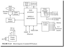
Figure 11.21 depicts the block diagram of a typical DVD player. First, note the motor that drives the disc. It is a variable-speed device that changes speeds as the pickup mechanism moves from inside to outside as it reads the spiral track.
The pickup head uses a laser that shines on the disc to read the pits and lands. Because of the closer spacing, a higher-frequency (shorter wavelength) laser is used. CD players use a 780-nm laser, while DVD players use a 640-nm laser that has a smaller focused beam.
The photodetector in the head picks up the laser reflections and sends the 10 Mb/second data stream to the processing chips. In some players, a single- chip application-specific device handles all of the digital processing from demultiplexing, to error detection and correction, decoding, and MPEG-2 decompression. All this may be in separate chips in some players.
In any case, the MPEG-2 data goes to a video decoder and to multiple DACs that re-create the original analog RGB signals. Various video formats are used, such as RGB, YCrCb, and YPrPb, each of which needs three DACs each. Most DVD players also decode regular composite video and S-video.
The separated audio signals go to an audio codec that contains the DACs which recover the audio content either in basic stereo or 5.1 surround sound. As for interfaces, an HDMI output is provided. Most players also have an Ethernet port, IEEE 1394, and USB connections.
Don’t forget that some of the later models are also DVD recorders. They play DVDs but also burn new ones with video from the TV set, cable box, sat- ellite box, or a built-in tuner.
A Word about Blu-ray
Blu-ray is the next generation of DVD medium and players. The discs are the same size but thanks to even smaller pits, lands, and track spacing, even greater
storage capacity is available. With 320-nm track spacing and a 405-nm (blue light wavelength) laser, the single-sided disc can hold up to 25 GB of data. That is enough to store two full-length high-definition movies or 13 hours of standard-definition video. A double-layer version is also available that doubles those storage figures. Blu-ray uses MPEG-2 compression, but also supports other video compression standards such as MPEG-4/H.264 and VC-1.
For a while, there were several other video disc standards competing for dominance. The most notable was HD-DVD, which did bring players to mar- ket. Most movie companies and other media sources selected Blu-ray as the distribution medium, making Blu-ray players the de facto standard and elimi- nating HD-DVD.
Project 11.1
Look at a Pixel
Get a magnifying glass and hold it up to your TV screen to see the individual color pixels or subpixels. Are they triads or rectangular areas?
Project 11.2
Diagram Your Own TV System
Draw a block diagram of your own home TV setup. Just draw a box for each and indicate how each of them is connected. Identify the type of cable, connector, and interface between each box.
Project 11.3
Try Over-the-Air TV
If you get your TV by cable or satellite, try receiving local channels on an antenna. Use an indoor antenna for simplicity. You can buy a set of “rabbit ears” from a local Radio Shack. Or try an outdoor antenna from Radio Shack. You can get some channels on a simple loop of wire 1 yard long.
If you still have an older analog TV, you probably also have a cable box and went through this process before.
