Chapter 5: SCSI Bus
Overview
The Small Computer System Interface (SCSI) bus is used to attach various small devices to a computer. Devices that can be attached include data-storage devices with random access (hard disks) and sequential access (streamers), CD-ROM and CD-R/RW drives, automatic media changers, printers, scanners, communications devices, and processors. A SCSI device can be either a host-adapter, which connects the SCSI bus with an internal computer bus, or a target controller, which connects a device to the SCSI bus. There can be more than one host-adapter on a bus: This allows peripheral sharing by several computers connected to one SCSI bus.
The bus treats all devices as peers that can function as both exchange initiators and target devices. In most cases, however, the host-adapter is the initiator. Each target device can have up to eight independently addressed logical devices that have their own logical unit numbers (LUN) representing peripheral devices or their parts. The exchange initiator sends a command-containing message to the target device. Commands are used to control devices and, of course, to exchange data. Data exchange is controlled by the target device that receives a command. During this process, it occupies the bus only during the active data transfer, relinquishing it while it searches for the data. During this time, other devices can use the bus to exchange data, which makes the SCSI bus highly practical for working with a large number of devices under the control of multitask or multithread operating systems.
The SCSI command system has been meticulously standardized, which makes for a high level of compatibility between devices of the same class from different vendors or of different models. Devices are classified according to their functional purpose and the commands needed to interact with them. Every device must support commands mandatory for its class. There are also commands mandatory for devices of all classes. In mass storage devices of different classes (random access magnetic discs, serial access tapes, optical discs, etc.), SCSI uses only one type of addressing, Logical Block Addressing (LBA): This makes it possible for devices of different classes or storage capacity to interact in a uniform way. Moreover, this allows blocks of data to be copied from one SCSI device to another directly, without the intermediate step of placing them into the computer’s main memory. There also are keyword data search commands for mass data storage devices. SCSI supports command chains up to 256 commands long, in which execution results of a previous command (the address of the found block in a data search, for example) can be used as parameters for the next command. This makes it possible to unload the host even when performing quite sophisticated data storage and retrieval procedures. True, far from all of these advanced features are actually used by operating systems and applications. But even without them, the ability of SCSI devices to work independently of each other gives SCSI unarguable advantages over ATA as an interface for high-end data storage systems.
The first version of the bus, later called SCSI-1, was standardized by ANSI in 1986 (X3.131-1986). It was an 8-bit parallel bus with a maximum switching frequency of 5 MT/sec1, to which up to 8 devices could be attached. Data transfer was carried out at up to 5 MBps in the asynchronous mode. Later, in 1991, the SCSI-2 (X3.131-1994) specification appeared, expanding the capabilities of the bus. The Fast SCSI-2 bus has a switching frequency of up to 10 MT/sec, while the Ultra SCSI-2 reaches frequencies of up to 20 MT/sec. Bus width can be increased to 16 bits. The 16-bit version is called Wide SCSI-2; the 8-bit version is called Narrow SCSI-2. The SCSI-2 standard also defined a 32-bit version of the interface that has not yet been applied in practice. The synchronous data-transfer mode and a different version of the interface have also been introduced. The SCSI-2 specification defines a command set including the common one that all peripheral devices are required to support. It also defines specific command subsets to support peripheral devices of various classes. The standard completely describes the device-interaction protocol, including the structure of the transmitted information.[1]
The SCSI-3 specification is a further development of the standard, aimed at increasing the number of attached devices, broadening the command set, and supporting plug-and-play technology. As an alternative to the parallel SPI (SCSI-3 Parallel Interface) interface, the possibility of employing serial interfaces, including fiber-optic interfaces with speeds of 100 MBps, has been made available. SCSI-3 is a plentiful collection of documents defining separate aspects of the interface on the level of the physical connections, transport protocols, and command sets. On the transport level, various protocols that have the appropriate support for physical connections can be used:
-
SCSI Parallel Interface (SPI) deals with the parallel interface (connectors, signals).
-
SCSI-3 Interlocked Protocol (SIP) is a traditional interface exchange protocol implemented physically by the SPI interface.
-
Fibre Channel Protocol (FCP) is a fiber channel protocol with the corresponding physical level of FC-PH and a data-transmission rate of 100 MBps.
-
Serial Bus Protocol (SBP) is implemented by the 1394 (FireWire) interface.
-
Generic Packetized Protocol (GPP) is a general-purpose packet protocol, implemented by any packet interface.
-
Serial Storage Protocol (SSP) is implemented using Serial Storage Architecture (SSA).
The chronology of the development of the parallel interfaces in SCSI-3 is as follows:
-
The SPI standard (1995) defines the SCSI-3 P-cable, a one-piece cable with 68-pin connectors for the wide bus. It also defines the Fast SCSI transfer rate (Fast Wide SCSI working at 20 MBps). Later, the supplementary Fast-20 specification, better known as Ultra SCSI, was adopted (Ultra Wide SCSI working at 40 MBps).
-
The SPI-2 standard (1999) again doubled the switching frequency due to its use of the LVD interface. The Fast 40 SCSI interface is better known as Ultra2 SCSI (Wide Ultra2 SCSI with transfer speed of 80 MBps). It introduced the Single-Connector Attachment connector (SCA-2), which allows “hot-swap” connections, and the 68-contact Very High Density Cable Interface connector (VHDCI). SPI-2 includes both the SCSI-2 A-cable and the SPI P-cable. It is a complete document in itself, without reference to the preceding standards, and defines all the SCSI parallel interfaces, up to and including the Fast-40.
-
The SPI-3 standard (2000) doubled the transfer frequency, but this time by making use of the Fast-80DT (DT means double transition) double-synchronization interface, known as Ultra3 SCSI or Ultra 160. This mode utilizes only the wide (16-bit) version. The traditional (high-voltage) differential version was abolished, as was the 32-bit bus and the Q-cable. Only the LVD interface and synchronization using the positive and negative transitions of the REQ#/ACK# signals were considered. CRC transmission control, packetized commands and messaging, and quick arbitration were introduced. This standard is also a complete document in itself. It describes all the SCSI parallel interfaces and abolishes HVD, SCSI Configured AutoMatically (SCAM), and the 32-bit bus.
-
The SPI-4 standard (2001) doubled the switching frequency producing the Fast-160DT interface, already known as the Ultra320 SCSI. It uses only the wide bus with transfer rate 320 MBps.
[1]MT/sec: Mega Transfers/sec. It is incorrect to call it the clock rate, as there is no timing-clock signal on the bus.
5.1 SCSI Parallel Interfaces
There are several versions of the SCSI parallel interface. They differ in bus widths and in their methods of signal transmission and synchronization. Physically, the narrow SCSI interface is a bus consisting of 18 signal and several power lines. In the wide version, the number of signal lines is greater. Each signal line has its own return wire to reduce noise interference. The contacts of the signal and return lines in the 2-row connectors are located opposite each other. This allows the use of both twisted-pair wires and flat ribbon cables in which the signal and return wires alternate.
SCSI is divided into two categories by the type of signal used: single-ended and differential. They use identical cables and connectors, but have devices that are not electrically compatible.
In the widely used single-ended version, each signal is sent by a TTL-level potential referenced to the common wire. Every signal must have a separate common (return) wire to reduce crosstalk interference. SCSI-1 uses open-collector transmitters and receivers built on bipolar transistors. Passive terminators are employed to keep the signal level high when transmitters are inactive (see Section 5.1.4). In SCSI-2, active-negation transmitters also started to be used. To remove the signal, an open-collector circuit “drops” the line, and its potential is returned to the initial state only by the terminators. When active negation is used, the output circuit of the transmitter briefly forces the line into passive-state potential, after which it “releases” the line. This creates the illusion that it is possible to operate without terminators. In SCSI-3, the SPI standard prescribes CMOS-interface integrated circuits.
The differential version (Diff or HVD) sends a paraphase signal on a wire pair. It uses the same special differential transceivers as the RS-485 interface, which allows significantly greater cable length while preserving the exchange rate. The differential interface is used in server-disk systems, but is not common in standard PCs. The HVD interface (under its old name of Diff) was introduced in SCSI-2, but SPI-3 (SCSI-3 in 1999) abolished it as it could not support the speeds of Ultra2 and higher.
The Low-Voltage Differential interface (LVD) allows Ultra2-, Ultra160-, and Ultra320-class devices to work at transfer frequencies of 40 MT/sec, 80 MT/sec, and 160 MT/sec on buses 80 feet long (8 devices) or 40 feet long (16 devices). LVD devices are compatible with single-ended devices because of their automatic-reconfiguration capability (Multimode LVD). LVD devices sense the voltage level on the DIFFSENS line and can switch from the LVD (differential) mode into the single-ended mode at low voltage levels. The connector contact, to which this line is attached, is grounded, so all devices attached to the bus automatically switch to the single-ended mode if there is even one single-ended device present on the bus.
Data-transfer rate is determined by signal-switching frequency (measured in MT/sec), bus width, and, in later versions; also by the method of synchronization (single-or double-transition clocking). The first SCSI buses were 8 bits wide (Narrow) and had switching frequencies of up to 5 MT/sec. The wide version of the bus is 16 bits wide. The combination of these parameters provides a broad throughput range (Table 5.1) reaching up to 320 MBps. The terminology used to indicate the throughput of various interfaces varies; in this book, I shall use the designations used by Western Digital in 2000. Fast SCSI means transmission frequency of 10 MT/sec; time diagrams for this mode are defined by SCSI-2. Fast-20 denotes Fast Wide SCSI (16-bit bus width, 10 MT/sec switching frequency). The Ultra SCSI mode indicates a transfer frequency of 20 MT/sec. It is defined for the parallel interface by the SCSI-3. Fast-40 corresponds to Wide Ultra SCSI (16-bit bus, 20 MT/sec switching frequency). Ultra2 SCSI indicates a switching frequency of 40 MT/sec. Fast-80 means Wide Ultra 2 SCSI (16-bit bus width, 40 MT/sec switching frequency). This mode, defined by SCSI-3, currently is the most widely used by new devices with parallel buses; it has been implemented only in the low-voltage differential version of the interface (LVD). The concept of Ultra3 SCSI in SCSI-3 is rather broad. Ultra 160 SCSI indicates a speed of 160 MBps and exists only in the wide (16-bit) version. It uses double-transition clocking and employs CRC to control data integrity, which means it can “squeeze” the maximum transfer rate out of the cable (like the Ultra DMA ATA interface). In 2001, the Ultra320 SCSI interface came out, with speeds of 320 MBps.
Table 5.1: Data-Transfer Rates (MBps) in the Parallel SCSI Bus
The most popular interface, Ultra2 SCSI, provides a good combination of bus throughput, length, device cost, and compatibility with traditional SCSI devices.
5.1.1 Bus Protocol
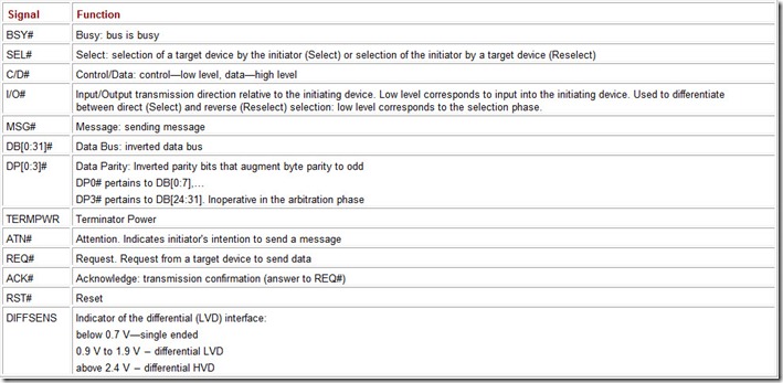
Table 5.2 shows the functions of parallel-bus signals. All signals are low-active: Low potential corresponds to the active state and to logical one, marked here by the # character. The reverse, or paraphase, circuits are marked by the + character.
Table 5.2: Functions of the SCSI Bus Signals
Every SCSI device connected to the bus must have a unique address, which is assigned to it when the device is configured. For the 8-bit bus, the address value range is from 0 to 7, while for the 16-bit bus it is from 0 to 15. The address is assigned by setting switches or jumpers. A host adapter can be configured using software. Addressing devices on the bus during the selection phase is carried out using the SCSI ID identifier, which presents the address in positional code. The device’s address is defined by the number of the data-bus line that selects given device. A device with an address of zero is selected by the low level on line DB0# (SCSI ID=00000001); a device with an address of seven—by the low level on line DB7# (SCSI ID=10000000). The identifier value determines the device’s priority in using the bus, and the device with the highest address has the highest priority. The address and identifier concepts are often confused, but they are simply two different ways of referring to the same parameter.
Only two devices can use the bus to exchange information at any one moment. The exchange process is set off by the exchange initiator and executed by the target device. The exchange initiator selects the target device by its identifier. In most cases, the devices’ roles are fixed: The host adapter is the exchange initiator and a peripheral device is the target device. Combination devices, which function as both the exchange initiator and the target device, are also possible. In some cases, devices can switch their roles: Having completed the arbitration phase, the exchange initiator may perform reverse selection (Reselect) of the target device to continue the interrupted operation. When executing the copy command, the exchange initiator directs the copying master device to perform data exchange that may also be performed with another target device, in which case the copying master device functions as the exchange initiator.
Information is transferred through the data bus, one byte (or word) at a time, asynchronously, employing request (REQ) acknowledge (ACK). Each byte is checked on odd parity (except at the arbitration phase), but this control may be disabled. The interface has the capability for synchronous data transfer, which increases the exchange rate. (SCSI-1 did not have the synchronous transfer feature).
The bus may be in one of the phases listed below. The functions of the signal sources between the exchange initiator and the target device are described in Table 5.3.
Table 5.3: SCSI Signal Sources
[1]AA: signal source is a device arbitrating for bus control.
[2]WA: signal source is the device that has won the arbitration.
[3]SID: each device controls only 1 data bit, which corresponds to the value of its SCSI ID.
[4]I: signal source is the exchange initiator.
[5]T: signal source is a target device.
In the Bus Free phase, the bus is inactive: No transfer processes are taking place, and it is ready for arbitration. This phase is indicated by the passive state of the BSY# and SEL# lines.
In the Arbitration phase, a device can obtain the right to control the bus. When the bus is free, a device asserts the BSY# signal and its SCSI ID identifier. If several devices assert their address lines at the same time, the device with the highest address receives the right to control the bus, and the rest of the devices disconnect until the next time the bus is free. The device that wins the arbitration asserts the SEL# signal and proceeds to the Selection or Reselection phase.
In the Selection phase, the exchange initiator that has won the arbitration performs a logical OR function on two identifiers—its own and that of the target device—then adds a parity bit to the result and places the final result on the data bus. By asserting the ATN# signal, the exchange initiator indicates that the following phase will be Message OUT. Next, the exchange initiator deasserts the BSY# signal. (The absence of an I/O# signal differentiates this phase from the Reselection phase.) The addressed target device responds with a BSY# signal if the parity is correct and there are only two identifiers on the data bus (its own and that of the exchange initiator). Devices do not react to wrong data. If during the predetermined time the target device does not answer, a time out is triggered and the exchange initiator releases the bus or asserts the reset signal RST#.
The Reselection phase is analogous to the Selection phase, but is initiated by a target device. This phase is introduced when a target device disconnects from the bus while a command is being executed. When the internal operation is completed, this device, having won the arbitration, will call the exchange initiator that initiated the operation. The target device deasserts the BSY# signal. (The active I/O# signal distinguishes this phase from the Selection phase.) The addressed exchange initiator responds by asserting the BSY# signal line. The response and time-out conditions are analogous to the previous phase.
During the Command, Data, Status, and Message phases, the bus is engaged in information transfer; the phases are identified by the MSG#, C/D#, and I/O# signals (Table 5.4), which are controlled by the target device. The exchange initiator may request to send a message (Message OUT phase) by asserting the ATN# signal line, and the target device may let go of the bus by deasserting the MSG#, C/D#, I/O#, and BSY# signals.
Table 5.4: SCSI Information Phases
Fig. 5.1 shows time diagrams for asynchronous exchange. Here, the transmission of each byte is accompanied by an interclocked pair of REQ#/ACK# signals. The exchange initiator latches in the incoming data at the trailing edge of the REQ# signal. The target device considers the received data valid at the trailing edge of the ACK# signal. The asynchronous-transfer mode is supported by all devices during all information-transfer phases.
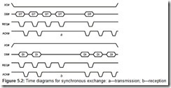
If the devices agree, the data-transfer phases Data OUT and Data IN can also be carried out in the synchronous-transfer mode, time diagrams for which are shown in Fig. 5.2. During negotiation to the synchronous mode, the minimum lengths and periods of the ACK# and REQ# control signals are established, as is the permissible time lag between requests and acknowledgements (the REQ/ACK offset agreement). The target device sends a series of data accompanied by REQ# strobes (Fig. 5.2, a), at a rate bounded by the set timing parameters. The exchange initiator latches the input data at the negative edge of the REQ# signal, but can confirm the data by the ACK# signal only after some delay. As soon as the lag between the sent ACK# and received REQ# signals reaches the predetermined limit (2 in the present example), the target device will suspend the exchange until the arrival of the next ACK# confirmation. The operation is considered to have been completed when the number of received acknowledgements matches the number of sent requests. When data are received by the target device, the negotiation mechanism is the same, but data are latched at the negative edge of the ACK# signal (Fig. 5.2, b).
Caution
The SCSI-1 specification does not explicitly describe when the transmission is resumed after the lag has been eliminated. As a result, developers could assume that the next request (and data) could follow only after the end of the positive transition of an ACK# signal. A device constructed with this assumption can lose data, as the last REQ# signal appears unexpected to it (as do the data) and looks as though it exceeds the negotiated offset.
16-bit exchange is done in a similar way. If not all bytes are used in the last data phase, the transmitter must set the correct parity for the unused bytes as well.
Time delays were not mentioned in the descriptions of data-transmission phases. The specification defines them in such a way that a potential “skew”—signals’ not arriving at the same time because of delays caused by the electronic circuits or by different cable wires—will not affect the stability of the protocol. In the asynchronous mode, the data-transfer rate also is affected by the length of the cable, as changes in the transfer participants’ states propagate along the cable at limited speed. If the wide bus consists of two cables (A and B, although this does not often happen in practice), then each of them has its own pair of control signals (REQ#/ACK# and REQB#/ACKB#) because the cables may be of different lengths.
During the Command phase, the target device requests a command from the exchange initiator. In the Status phase, the target device makes a request to send the exchange initiator information about its state. In the Data IN and Data OUT phases, the target device makes requests for transmitting data to and from the exchange initiator, respectively. The Message IN and Message OUT phases are used to send messages. The Message OUT phase is launched by the target device in response to the Attention condition, created by an ATN# signal from the exchange initiator when it needs to send a message to the target device. The Message IN phase is initiated by the target device when it needs to send a message to the exchange initiator.
The BSY#, SEL#, REQ#, and ACK# signals cannot change their states between data-transmission phases; only the C/D#, I/O#, MSG#, and the data-bus signals can change.
The ATN# and RST# signals can initiate the Attention and Reset conditions, respectively; moreover, they do this asynchronously with respect to the bus phases. These conditions may lead to a change in the predetermined sequence of phases. The ATN# signal is asserted by an exchange initiator at any phase, except in the Arbitration and Bus Free phases. The RST# signal may be asserted by any device, and all devices must release the bus upon Reset. Depending on the setup parameters adopted for all devices of the particular system, two reset versions are possible. The “hard” reset places devices into the state assumed when the power is turned on, clearing all current processes, queues, etc. With the “soft” reset, devices attempt to complete the operations in progress, preserving the current setup parameters, when the bus becomes available.
An input/output process consists of the following sequence of bus phases: from the Bus Free phase, a transition is made into the Selection or Reselection phase via the Arbitration phase. Then follow the Command, Data, Status, and Message information-transfer phases. The final phase is the Message IN phase, during which the Disconnect or Command Complete message is sent. The bus then goes into the inactive Bus Free phase.
The SCSI architecture allows each input/output process to save a set of three pointers (saved SCSI pointers): command, status, and data. The exchange initiator has the current set of pointers (only one), into which the saved set for the current process is copied. The current pointers point to the bytes of the next command, status, and data, which are going to be transferred between the exchange initiator and the target device. The saved command and status pointers always point to the start of the command and status descriptor blocks. The saved data pointer points to the beginning of the data block until the target device sends the Save Data Pointer message. Upon receiving it, the exchange initiator saves the current data pointer. When the target device disconnects from the bus, information about the current I/O process is contained in the saved set of pointers. When the process is resumed, the target device may send a Restore Pointers message, requesting the exchange initiator to copy the saved set into the current set and to continue executing the commands of the given I/O process.
Caution
Because the target device may modify the data pointer before the I/O operation is completed, determining the real amount of data transferred using the pointer does not produce reliable results.
5.1.2 Interface Control and Command Execution
The Message System—a system of message exchange between the exchange initiator and the target device—is employed to control the interface. Exchange takes place during the Message IN/OUT phases; several messages can be sent during one phase.
Synchronous-mode parameters and data width are negotiated using messages. The process of negotiating synchronous-exchange parameters is called Synchronous Negotiation. Devices requesting synchronous exchange send a Synchronous Data Transfer Request message indicating the acceptable cycle period and REQ/ACK lag. If the other exchange participant supports the synchronous mode, it will offer its parameters. Parameters that need to be negotiated are the maximum period and the minimum lag (zero lag is equivalent to asynchronous mode). The selected mode will be valid only for the phases of transmission between the given pair of devices. A rejected message is a request for the asynchronous mode. Because old host adapters did not support synchronous-mode negotiation, a target device may have its synchronous-mode request feature disabled. The host can determine whether synchronous-mode operation is possible by sending the Request Sense and Inquiry commands.
The width of transmissions is similarly negotiated, using the Wide Data Transfer Request. The negotiated modes will be valid until the devices are reset by the Bus Device Reset message or by a hard reset, which will cause the devices to switch into the default power-on mode. Transmission-mode negotiation should not be initiated in every process, since time expenditures on this procedure can nullify any productivity gains.
The SCSI command system includes common commands supported by all classes of devices, as well as commands specific to individual classes. Any SCSI device must support the mandatory commands of the common set and of its class, which provides a high level of compatibility. Commands are transmitted by an exchange initiator to a target device via the command descriptor block sent during the Command phase. Some commands are accompanied by a parameter block that follows the descriptor block during the Data phase. The block formats are standardized; block length determined by the operation code (the first byte in the block) may be 6, 10, or 12 bytes.
As an example, the SCSI bus process can be considered using a single command: Read. The exchange initiator has the active set of pointers and several saved sets, one for each of the permitted number of simultaneous contenting processes. The exchange-initiator restores the process pointers to the active set and, having won the arbitration, selects a target device. As soon as the target device is selected, it takes control over the process. During the Selection phase, the exchange initiator asserts the ATN# signal, informing of its intention to send an Identify message that indicates the addressed logical device. The target device goes into the Command phase and receives the descriptor block of the Read command. Having interpreted the command, the target device goes into the Data IN phase and sends the requested data, then goes into the Status phase and sends the status Good. Then, in the Message In phase, the device sends a Command Complete message, after which it releases the bus (Bus Free phase). The process has been completed.
The same example can be considered with a disconnection from the bus in the process of the command execution. If a device that receives the Read command determines that it will take it a long time to prepare the requested data for transmission, it will release the bus by sending a Disconnect message. As soon as the target device has the requested data ready, it goes into arbitration. Having won it, the device will select the exchange initiator (during the Reselect phase), and during the Message In phase will send an Identify message to the exchange initiator. The exchange initiator will return the corresponding set of pointers to the active state and will continue executing the process as described earlier. If the target device wants to disconnect when a portion of data has already been transmitted (e.g., if a disk head has reached the end of the cylinder and needs to be repositioned), it sends a Save Data Pointer message followed by a Disconnect message. After reconnecting, transmission will resume from the point defined by the last saved pointer value. In case of an error or exception, the target device can repeat the data exchange by sending a Restore Pointers message or disconnecting without sending a Save Data Pointers message.
The process could also include a chain of linked commands. Upon successful completion of each command in the chain, the target device automatically begins executing the next one. All the commands in the chain are part of a single process. The commands are not completely independent: When relative addressing is employed, the block addressed by the last command is accessible to the next one. For example, by executing a Search Data command, the block of the disk containing the information that matches the search template will be found. By linking the Read command to the Search Data command, this block or a block with the specified offset relative to the found one can be read. When execution of the linked commands is complete, the target device sends a Linked Command Complete message (possibly with a flag), and the exchange initiator refreshes the set of the saved pointers so that they point to the next command in the chain. Commands in the chain are executed as being single but with the potential for relative addressing.
Commands may be executed using queues. Target devices can support tagged and untagged queues. Support of the tagged queues, which was defined as early as SCSI-1, allows any logical unit number or a target program executing a process from one exchange initiator to accept commands (launch a process) from other exchange initiators.
Tagged queues are defined in SCSI-2 for logical unit numbers. For each exchange initiator-target device-logical unit link, there is a queue up to 256 processes long. Each process employing tagged queues is identified by an I_T_L_Q link, where Q is a one-byte queue tag. Tags are assigned to the processes by the exchange initiator; their values do not affect the sequence, in which operations are executed.
Queue placement is done by a messaging mechanism. Moreover, the next process may be placed into the queue either “honestly” or may jump the line: A process placed into the queue with a Head of Queue Tag message will be executed immediately after the active process is completed. Processes placed into the queue with Simple Queue Tag messages are executed by the target device in the sequence that it considers to be optimal. A process placed into the queue with an Ordered Queue Tag message will be executed last. The exchange initiator can remove a process from the queue by referencing it by its tag. Changing the order, in which the target device executes commands, does not affect the command order in the chain, because the chain belongs to a single process; it is the processes that are placed into queues.
The various situations that can lead to deviations from the interface’s normal event sequence are not considered here. These situations include erroneous connections by the exchange initiator, the selection of a non-existent logical unit number, unexpected exchange-initiator selections, parameter rounding, reaction to asynchronous events, etc.
5.1.3 Cables, Connectors, and Signals
Flat ribbon or round flexible cables are typical for parallel interfaces. Flat ribbon cables are used to connect internal devices. They can have several connectors. If necessary, cables can be linked using special matching connectors but only of the butt type. (T-connectors are not allowed, although it is possible to have a branch of less than 4 inches, including the length of cable from the branch to the input of the transceiver’s integrated circuit.) Twisted-pair round cross-section cables are used to attach external devices. External peripheral devices usually have two connectors, allowing them to be connected in chain. The length of the cable depends on the interface version and the frequency (Table 5.5). When calculating the overall cable length, the possibility of employing one host adapter port simultaneously for external and internal connections must be considered. In this case the lengths of the external and the internal cables must be added up. Cable connectors are always connected one-to-one to contacts of similar circuits.
Table 5.5: Maximum Lengths of SCSI Cables
The variety of connectors used in SCSI devices is now so diverse that matching adapters sometimes need to be used. Connectors vary in the number their contacts, as well as in the contacts’ shape and size. Practically all connectors are of the two-row type, and the layout of the contacts is designed for the alternation of the signal and return wires. The exceptions are DB-25 connectors, which have fewer earth contacts than signal contacts, and three-row DB-50 connectors. Connector types are as follows:
-
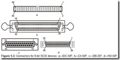
IDC-50 connectors (analogous to ATA 40-pin IDC-40 connectors) are used for connecting internal devices. They have square pins spaced 0.1 inch (2.54 mm) apart and plastic cases without additional casing or latches (Fig. 5.3, a). Devices are fitted with plugs (IDC-50M); ribbon cables are fitted with sockets (IDC-50F).
-
CX-50 are Centronics-type connectors, analogous to those used on printers, but with 50 contacts. They have flat contacts spaced 0.085 inches (2.16 mm) apart and have a metal casing (Fig. 5.3, b). X-50 connectors are used to attach external devices. Devices (and SCSI adapters) are equipped with sockets (CX-50F); cables are equipped with plugs (XC-50M). To secure connectors in place, female connectors have wire latches that snap into notches on male connectors. These connectors are often called SCSI-1 External.
-
DB-25 are connectors with round pins enclosed in a D-shaped protective shell (like LPT port connectors). Devices are equipped with female connectors (DB-25F), cables are equipped with male connectors (DB-25M); connectors are secured in place by screws (Fig. 5.3, c). These connectors are used on some external devices, such as Zip drives).
-
HD-50, or MiniD50, (Fig. 5.3, d), connectors have pins enclosed in a metal D-shell. They are high pin-density connectors, with pins 0.05 inch (1.27 mm) apart. Devices are equipped with female connectors (HD-50F), cables with male (HD-50M) connectors. Connectors are secured in place by a clip-type latch.
-
HD-68HD-68, or Mini68, connectors are similar to HD-50, but have 68 contacts. Devices are equipped with female connectors (HD-68F or MiniD68F), cables are equipped with male connectors (HD-68M or MiniD68M). External connectors are secured in place by clips or screws, internal connectors are held in place only by friction. They are often called SCSI-3 connectors and now are most commonly used for the wide SCSI interface. Fig. 5.4 shows an external connector; the left part shows the clip type latch, the right part shows the screw bushing.
-
VHDCI-68 are very high density, Centronics-type external connectors with contacts spaced 0.8 mm apart. They are seldom used. Sometimes they are mistakenly referred to as SCSI-4 or SCSI-5 connectors.
-
MCX (Micro-Centronics) are miniaturized versions of Centronics-style connectors. The most commonly used are MCX-68 and MCX-80 connectors, better known as SCA connectors.
-
Single Connector Attachment (SCA) connectors are used to attach devices using only the connectors (i.e., using no cables). They are meant to connect internal disk drives with the possibility of hot-swap replacement (or at least easy replacement via the front panel). Currently, the prevalent is the SCA-2 specification implemented in MCX-80 connectors (Fig. 5.5). Devices are equipped with male connectors (MCX-80M), while female connectors (MCX-80F) are installed on computers. In addition to the regular interface signals, an SCA connector includes all the power and configuration signals needed by the device (identifier, modes, etc.). The side guides of the connector have additional contacts for the ground connection. Configuration jumpers are installed on the computer case or the adapter card, not on the device.
Narrow SCSI uses the connectors depicted in Fig. 5.3, while Wide SCSI uses those shown in Fig. 5.4. Miniature D-shape SCA-2 connectors accommodating all the power and signal circuits needed by a device are used to attach hot-swap devices.
SCSI also employs a broad variety of cables:
-
A-cable is the standard cable for 8-bit interfaces. It has 25 wire pairs. Flat ribbon cable is used for connecting internal devices; round cable consisting of 25 twisted pairs enclosed in a common shield is used for attaching external devices.
-
Internal SCSI-1 and SCSI-2 A-cable has low contact-density IDC-50 female connectors (see Fig. 5.3, a).
-
External SCSI-1 A-cable has Centronics-type CX-50M male connectors (Fig. 5.3, b).
-
External SCSI-2 A-cable has MiniD50M (HD-50M) male connectors (Fig. 5.3, c).
-
-
P-cable is a 34-wire-pair, 8- or 16-bit cable with improved, shielded miniature connectors. It is used in SCSI-2 and SCSI-3. Contacts 1-5, 31-39, and 65-68 are not used in the 8-bit version.
-
Internal SCSI-3 P-cable has HD68M male connectors without latches.
-
External SCSI-3 P-cable has MiniD68M male connectors with latches.
-
External SCSI-2 SPI-2 P-cable has VHDCI-68M high contact-density male connectors. (It is sometimes mistakenly called a SCSI-4 or SCSI-5 cable).
-
-
Q-cable is a 68-wire expansion to the 32-bit bus used in pair with the P-cable and has an analogous construction. Q-cable has never been used in practice, and the SCSI SPI-3 specification no longer recognizes it.
-
Mac SCSI is an 8-bit cable with DB-25P connectors (Fig. 5.3, d). It is a standard cable for Macintosh computers, used to attach some external devices, such as Iomega Zip drives. If a 25-contact connector is installed on the host adapter, the cable has a different line layout.
There are also various types of matching adapters and cables, with different types of connectors. Adapters are produced as a printed circuit board or a monolithic construction with different types of connectors on opposite ends. Adapters that connect buses of different widths may have a high-order byte terminator, which must have a disconnect feature (see Section 5.1.5). Adapters for attaching SCA to a regular bus have standard power connectors, as well as a set of device-configuration jumpers.
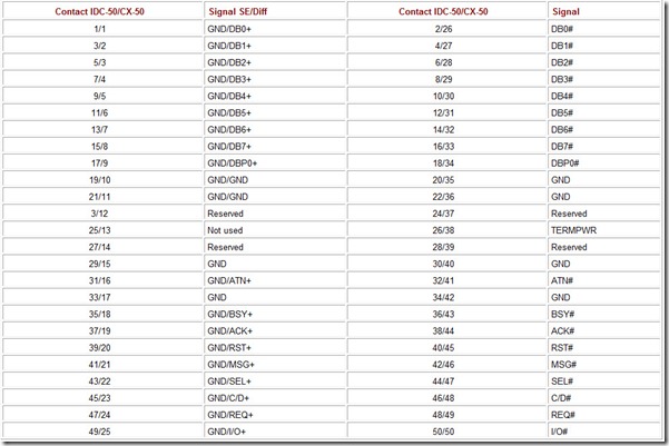
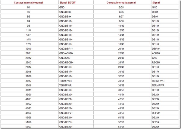
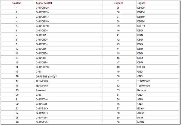
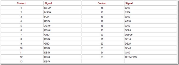
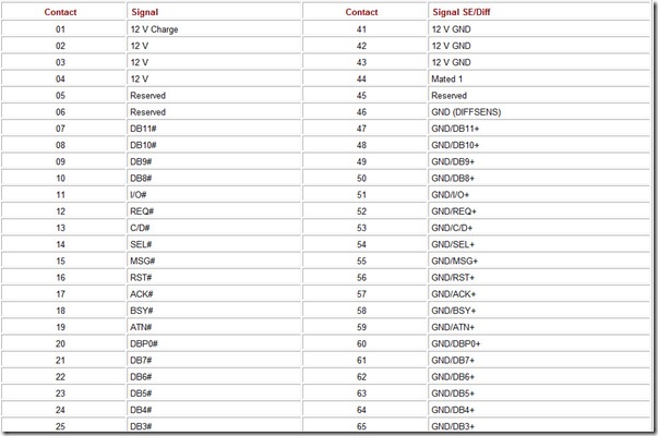
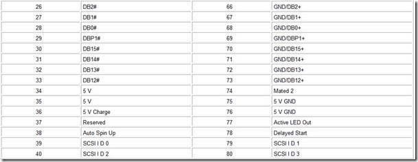
Tables 5.6–5.10 list the functions of SCSI cable connectors’ contacts. The contact numbering system, which is different for external and internal connectors, is inconvenient. However, the physical layout of the contacts on the connector and wires in the flat ribbon cable is the same. Signal lines alternate with return lines, which are grounded in single-ended devices.
Table 5.6: SCSI A-Cable Connector
Table 5.7: SCSI B-Cable Connector
Table 5.8: SCSI P-Cable Connector
[1]The DIFFSENS signal is defined only for the LVD interface.
Table 5.9: Mac SCSI Connector (DB-25)
Table 5.10: SCA-80 Connector
5.1.4 Terminators
All physical SCSI buses must have terminators installed on both ends. These terminators can be either internal (installed inside the controllers or peripheral SCSI devices) or external (small modules attached to the cable connector or to the auxiliary connector of the last device on the bus). SCSI-bus terminators must accomplish two objectives:
-
Ridding the bus of the signals reflected from its ends
-
Providing the necessary passive-line signal level
The first objective stems from the fact that SCSI cables can be long, and according to the theoretical basics of electrical engineering every signal line is a “long line.” To stop reflecting electrical signals from the ends of the line, both ends of the line must be loaded with matching loads. (“Matching” means that the wave impedance of the line must match the dynamic impedance of the load. The wave impedance of SCSI ribbon cables usually lies between 85 ohms and 110 ohms.) If a line is not terminated (or if its impedance does not match that of the terminator), the “jingle” of reflected signals will cause interference on the bus.
The second task is necessitated by the specifics of the SCSI interface, where each signal line can be controlled by any of several devices attached to the bus. However, the sending device stipulates only the active level of the signal (low in non-differential SCSI versions), and the terminators are responsible for returning the line to the passive state. If there are no terminators at all, then the level on the lines “released” by the device will also return to passive state, under the influence of the input currents of the signal receivers, but it will happen much later. If a bus is long enough and has many devices attached, then this return will be severely delayed and may cause protocol malfunctions. High-speed devices employ an active-signal negation technique to return signals to the passive state, creating the illusion that a bus can work without terminators. However, stable operation with numerous devices (more than two, including the controller) on the line without terminators is problematic.
From this, it is clear when it is possible to neglect the rules for installing terminators: when the bus is not too long, there are not many devices attached to it (e.g., just a controller and a hard drive), and the exchange speed is low. However, more often, one SCSI bus has many devices attached, making the bus quite long. (Additionally, users try to operate devices at high transfer rates and with elevated reliability requirement.) In some cases, it would be better to use devices with a different interface. For data-storage devices, this would be the widely-used and inexpensive ATA interface.
There are different terminators for single-ended and LVD devices, which are the most popular. Many LVD interface devices are capable of working with a single-ended interface (but at low speeds), and are marked “LVD/SE.” These devices are capable of determining the operating mode automatically: If all the devices on the bus (including the terminators) support the LVD mode, then this mode will be selected (if no device has been forced into the single-ended mode). If there is even one device on the bus capable of operating only in the single-ended mode, then the other devices will switch into this mode, reducing the maximum data-transfer speed. HVD (Diff) devices must not be included in the LVD/SE category.
The transmission methods and termination schemes are different for the single-ended and LVD transmission modes. Each SCSI-bus signal circuit consists of a pair of conductors: forward and reverse. In the single-ended mode, all the reverse conductors are grounded on each device, and the terminating circuits are connected only to the forward conductors. In the LVD mode, the signal is sent on a pair of wires in a differential paraphase form, while the terminating circuits are connected to the both wires of each pair. Fig. 5.6 shows possible terminator-circuit schematics for the single-ended and LVD transmission modes; load circuits are shown for one signal line. All terminators, not only those that are active, need to be powered. They are powered from special TERNPWR (+5 V) lines.
-
Passive single-ended terminators (Fig. 5.6, a) have an impedance of 132 ohms, which is not a good match for the bus’ ribbon cable. These terminators can be used only with a regular SCSI interface (transmission speeds up to 5 MBps to 10 MBps in the narrow/wide versions). They cannot be used with Fast SCSI, Ultra SCSI, or higher versions.
-
Active single-ended terminators (Fig. 5.6, b) have an impedance of 110 ohms, which means they can be used at higher speeds in Fast SCSI. Their “active” mode consists only of having a +2.85 V reference-voltage source (RVS) powered from the same TERMPWR lines. The integrated circuits of the active terminators also have electronic keys connected serially into each line. The keys are controlled by a common signal that can turn the terminator on or off.
-
Forced Perfect Terminators for SE (FPT SE) are an improved version of active terminators that have diode-surge limiters. They are used in high-speed single-ended interface versions.
-
Terminators for LVD (Fig. 5.6, c) have a differential impedance of 105 ohms (linear impedance of 150 ohms). Two base voltage sources provide a 112 mV offset between the forward and reverse conductors in the passive state.
-
Universal LVD/SE terminators combine active single-ended terminators, differential LVD terminators, transmission-mode detection circuits, and circuits for switching every SCSI bus conductor (forward and reverse) to the corresponding terminating circuits.
Universal LVD/SE terminators, like the other devices, detect the bus’ operation mode using the DIFSENSE line. In older single-ended devices, the connector contact corresponding to this line was grounded. LVD devices attempt to put a 1.3 V potential on the line, while HVD devices are used to put a voltage potential greater than 2.1 V on it. The terminator has comparators that compare the signal on the line with the reference signal, and logic that switches the terminator’s modes. (If HVD is detected, the terminator disconnects all its circuits). There are also integrated circuits produced specially for universal terminators (such as Dallas Semiconductor’s DS2117M, DS2118M) that perform all the automatic termination functions for nine pairs of wires. To terminate a 16-bit data bus (Wide SCSI), three such integrated circuits are needed. Laser-adjusted precision resistors are used in these integrated circuits, a technology that is not cheap.
In terms of physical implementation, terminators may be either internal (located on the printed circuit board of a device) or external (mounted on the cable or devices connectors). Internal terminators in every device can be turned on and off. In older devices (SCSI-1), a group of jumpers had to be set or a resistor network installed into a special socket to turn a terminator on. Active terminators are turned on and off by repositioning one jumper, or even, by software when configuring the device, without using jumpers. A terminator can even be turned on automatically if the device supports this option and it was enabled when the device was configured. External terminators look like connectors with a small cover concealing the insides. Despite their outer simplicity, they are rather expensive (a terminator for Ultra-Wide SCSI costs from $10 to $15). External terminators can only be mounted and removed manually.
Practically all non-LVD interface devices have internal terminators, or at least a socket for their installation. As a rule, LVD interface devices do not have terminators for reasons of economy. When several devices are attached to the bus, a terminator is employed only as the last device in the chain. However, when connecting only one such device, the savings are insignificant, but the expense of purchasing an external terminator is not.
Caution
The absence of terminators on LVD devices does not mean that termination requirements may be ignored.
5.1.5 Configuring SCSI Devices
All devices attached to the bus must be properly configured. They must have the parameters listed below set up either by software or by using jumpers.
-
The device identifier (SCSI ID) is a unique address from 0 to 7 (from 0 to 15 for Wide SCSI) for every device attached to the bus. The host adapter, which must have the highest priority, is usually assigned address 7 (15 for Wide SCSI if all devices are 16-bit). The positional code used for addressing provides addressing compatibility for 8- and 16-bit devices on the same bus. Some BIOS versions recognize as bootable only the device with SCSI ID = 0.
-
Parity control (SCSI Parity). If even one device does not support parity checking, it must be disabled in all the devices attached to the bus. Parity control, especially for disk drives, is an essential means of ensuring data integrity during bus transfers.
-
Termination. Modern devices use active terminators, which can be enabled by one jumper or by a software-controlled signal. Only the end devices in the chain are to have their terminators enabled. Modern host adapters have a feature allowing them to enable their terminators automatically if they are the last device on the chain, and to disable them if another device is attached to an internal or external bus connector. This allows external devices to be connected and disconnected without having to switch the terminators on the host-adapter card. Previously, to do this, it was necessary to open the case and move the jumpers for active terminators, or to install or remove passive terminators from their sockets. When there were no internal terminators, external ones, mounted on the cable, were necessary.
Caution
It is very important to install terminators correctly: No or too many terminators may result in unstable interface operation or in the interface being non-operational altogether.
-
Terminator power must be connected by a jumper (or by software) to at least one device.
-
Synchronous-exchange speed negotiation. The high-efficiency synchronous exchange mode is enabled by agreement between devices. Disabling negotiation on the host adapter is recommended if even one device on the bus does not support it. If the exchange is initiated by a target device that supports synchronous mode, a regular host adapter will support this mode. Use of the synchronous-transfer mode request on a target device may be disabled by a special jumper, which may be called “Enable Target Initiated Synchronous Data Transfer Request Negotiation” (TI-SDTR).
-
Enable disconnection—a parameter that allows devices to disconnect from the bus when there are no data during protracted operations with the data medium. This is quite effective in a multitasking mode with several peripheral devices attached to the bus. If there is just one device attached to the bus, disconnection only wastes time on reconnection.
-
Data-bus width negotiation is also executed using the bus protocol, based on the capabilities of each participant in the exchange. The 16-bit-mode request may be disabled in the target device by a special jumper, which may be called “Enable Target Initiated Wide Data Transfer Request Negotiation” (TI-WDTR).
-
Disable wide disables the 16-bit mode and allows a wide device to be attached to a narrow bus.
-
Force SE is a forced switch into the single-ended mode. It allows an LVD device to be switched into the single-ended mode, regardless of the state of the DIFFSENS line.
-
Disabling double transition clocking (Disable U160) allows a class Ultra3 SCSI device to be forced into the Ultra2 mode.
-
Start on command or Disable Auto Spin up. When this parameter is enabled, the motor of a device can start only on a command from the host adapter. This allows the power-supply load peak to be reduced when powering up the system. The host will start devices’ motors one by one.
-
Delayed Start, when employed in conjunction with delay-selection jumpers, allows a device’s motor to be started at a set interval after the power is turned on. (Each device is assigned a different delay period).
5.1.6 Connecting Devices to a SCSI Bus
Connecting devices to a SCSI bus is relatively simple, but there are certain peculiarities when mixing devices of different types on one bus. The throughput of the SCSI “mastered” by the computer is determined, naturally, by the potential of the host controller. SCSI buses provide good compatibility of parallel-interface devices of different generations—narrow and wide; but quite often, an older device can nullify the power of new devices that share the bus with it. The only compatible devices in interface terms are single-ended and LVD-mode devices.
Caution
LVD- and HVD-mode devices must not be attached to the same bus.
LVD devices can be mixed with single-ended devices on the same bus, but this will make all devices switch into the single-ended mode and the bus will not be able to operate in the Ultra2 mode intrinsic to LVD devices. The LVD interface, being differential, requires that every reverse wire (the + signal) come back to the input of its receiver; in the single-ended version, all reverse wires are bundled up together and connected to the bus ground. If there is even one single-ended device on a bus with LVD devices, the DIFFSENS line will be grounded, and all LVD devices will switch into the single-ended mode. At configuration, an LVD device can be forced into the single-ended mode by setting the Force SE jumper.
If there are Ultra 160 and Ultra2 (or even lower) devices mixed on the bus, then the bus will work in the lowest of these modes. The Ultra160 mode can be forced into the Ultra2 mode by the Disable U160 jumper.
Attaching a narrow device to a narrow bus is the simplest task, as only two types of connectors are encountered (not counting Mac SCSI): external (Centronics type) and internal. Devices must be preconfigured and each must be assigned a unique (for the bus) SCSI ID identifier, nominally any number from 0 to 7. The length of the bus must not exceed the permissible limit; at both ends of the bus (and only at the ends), terminators must be mounted and turned on. The TERMPWR line must be supplied with power (usually from the host adapter), which can be checked by measuring voltage on the appropriate connector contacts.
Attaching a wide device to a wide bus may turn out to be a bit more complicated because of the greater variety of connectors involved. This may require using matching adapters for the connectors. Difficulties may also arise when connecting terminators, especially for LVD devices, which seldom have internal terminators. External terminators may require a separate connector. The devices’ identifiers can be assigned numbers from 0 to 15.
Connecting a narrow device to the wide bus requires using a 68-pin-to-50-pin connector—matching adapter. The most significant byte in this adapter must not be terminated if the device being connected is not the last one on the bus. If the device is the last one on the bus, then the most significant byte in the adapter must have terminator ON, as well as the device itself. The decision on where on the bus to attach the device (in the middle or at the end) may be determined by the adapter on hand. Device identifiers between 0 and 7 must be assigned to all devices; otherwise, the arbitration procedure will not function properly because of the narrow devices’ inability to see the identifiers from 8 to 15. Since all narrow devices are of the single-ended type, the DIFFSENS line will be grounded, and all LVD devices will switch into the single-ended mode. There are, however, bridging adapters that allow LVD devices to remain in LVD mode even when a single-ended device is connected to the bus. The mode can be determined by measuring voltage on the 16th contact of a 68-contact connector (the 46th contact of an 80-contact connector).
Connecting a wide device to the narrow bus also will require using a special adapter and installing the Disable Wide jumper on the wide device. Additionally, the most significant byte and its associated control lines may have to be terminated to secure a reliable passive state on them. (“Hanging” inputs are susceptible to interference). Some versions of the firmware allow devices to work without additional terminators. The identifiers of all the devices must be between 0 and 7, for the same reasons as in the preceding case.
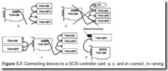
There are various configurations for attaching devices to a SCSI controller (Fig. 5.7). The controller may be implemented on a PCI- or ISA-slot expansion card or built into the motherboard. Devices that are connected to it can be internal (various types of disk and tape devices) or external (the same devices, as well as scanners and other peripheral devices). Terminators are installed based on the specific conditions.
The connection rules are relatively simple:
-
The ends of the ribbon cable must not hang in the air (Fig. 5.7, b).
-
Devices attached to the ends of the cable must have their internal terminators turned on (marked as TRM=ON) or have external terminators mounted (Fig. 5.7, d).
-
The devices attached in the middle of the bus must have their terminators turned off (marked as TRM=OFF).
If the SCSI controller is built on an expansion card, then the connector, to which external devices are attached, is located close enough to the internal connector, therefore there is no long line between them. In this case, terminating the external connector is no problem: If only the internal (Fig. 5.7, a) or only the external (Fig. 5.7, d) connection is used, then the terminator on the controller is turned on. If both the external and the internal connection are used (Fig. 5.7, c), then the terminator on the controller is turned off.
If the internal connection is used but the external devices are not connected at all the times, then it becomes necessary to switch the controller’s terminator to correspond to the current configuration. In older controllers, it was necessary to open up the system block and rearrange the jumpers. If for some reason you do not want to switch the controller’s terminator, you can turn it off permanently and use an external terminator mounted on the external connector (outside the computer case) when there are no external devices connected.
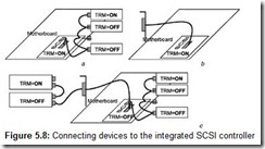
If the SCSI controller is built into the motherboard, ii has only one connector, to which a ribbon cable is connected. If an internal-only or external-only connection is needed (Fig. 5.8, a-b), then the terminator on the controller is turned on. If both the internal and external connections are used, then the terminator on the controller is turned off. If a universal ribbon cable with internal and external connectors is used (Fig. 5.8, c) but no external devices are connected, then the terminator on the controller must be turned off, and the external connector must have an external terminator mounted on it.
Cables and connectors may be supplied with SCSI adapters and motherboards that have a built-in SCSI controller, or they may have to be purchased separately. The supplied items are not always suitable for a particular purpose. For example, in the kit supplied with the CT-6BTS motherboard, which has a built-in Ultra-Wide SCSI controller, a universal wide ribbon cable (similar to the one shown in Fig. 5.8, c, but with fewer internal connectors) and an internal narrow one are included. This kit is not sufficient for attaching internal Wide SCSI disk drives, as an external terminator is needed. A possible solution might be to cut off the part of the ribbon cable going from the controller to the external connector, but that would be a waste.
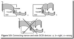
Wide SCSI controllers usually also have connectors for attaching regular (narrow) devices. As well as the 68-contact Wide SCSI connector, the CT-6BTS motherboard also has a regular, 50-contact connector for regular devices. The narrow (8-bit) interface may be considered as a subset of the wide (16-bit) that uses only the lower half of the data bus. Simple one-channel controllers (like the one on this card) have the contacts of their narrow connectors connected in parallel with a part of the contacts of the wide connector. This allows mixing of wide and narrow devices, for which the terminators on the controller are divided into two halves: Terminators of the least significant byte (TrmL) and those of the most significant byte (TrmH) can be controlled independently. Fig. 5.9, a-b shows the correct way to connect mixed devices (assuming that the devices at the ends of the ribbon cable have terminators). Fig. 5.9, c shows the wrong way of connecting mixed devices: In this case, the LSB and the control-signal lines will have either three terminators (causing transmitter overload) or a loose end (causing reflections). It is not possible to connect mixed devices correctly using only the standard cables supplied with the motherboard (shown in Fig. 5.9).
If these rules are followed (and neither the permissible cable length nor the number of connections is exceeded) then, provided all of the equipment is in good order, the SCSI bus will work reliably, as it is supposed to. If the rules are not followed, the consequences will vary. Certain models of controllers and terminators are more forgiving to some experimentation with terminators. (For example, they may forgive, or almost forgive, a loose unterminated cable-end, if it is not too long). These devices may work (the operating system will boot, drives will function) but, possibly with glitches that are not always visible. However, if the operating system being used is Windows NT, then looking into the event log will reveal a “bouquet”, or red flashes having to do with SCSI devices. How big this bouquet is will depend on the seriousness of the transgressions and the “temper” of the used devices. The necessary measures for each specific case are probably left up to the installer: There simply may be not enough money for an “extra” terminator or a cable of different configuration.
5.2 Fibre Channel Interface
As well as the parallel interface, SCSI-3 also can use the serial Fibre Channel interface, or Fibre Channel Arbitrated Loop (FCAL), which occupies an intermediate position between peripheral-device interfaces (SCSI-3) and LAN technologies. This interface can be implemented using electrical (coaxial cable), as well as fiber-optic conductors. In both cases, a frequency of 1 GHz provides a data-transfer rate of 100 MBps. Copper cable allows a bus length of up to 100 feet, while optical cable can extend up to 6 miles. This interface employs a different protocol and physical levels, allowing up to 126 devices be attached to the bus (not just 8 or 16, like with parallel interfaces). Point-to-point connections can operate in the full-duplex mode (200 MBps), which is not possible with regular parallel buses.
Adaptec has put on the market an adapter capable of operating at 2 GHz (in optical and copper channels) that is backward compatible with regular 1 GHz adapters. In the full-duplex mode, an aggregate throughput of 400 MBps can be reached. Up to 126 nodes can be connected in the ring, the length of which may reach up to 6 miles. The ring structure is similar to the Fiber Distributed Data Interface (FDDI): All the nodes are assembled into a closed chain and translate incoming frames further along the ring. Transmitters in all the nodes are synchronized separately, and between-the-frames filler words—some of which can be periodically discarded or inserted during the transmission—are used to compensate for the synchronization-frequency divergence. To provide reliable communications, 8B/10B coding is used; to obtain a 100 MBps transmission rate with allowances for the frame service data overhead, a line capable of supporting speeds up to 1.0625 Gbps is needed.
The architectural model of the FCAL consists of five levels: FC-0 to FC-4. The lowest level (FC-0) defines the transmission medium (fiber optic or twin-axial cable) and the physical interface. The top level (FC-4) defines the data-representation protocols related to both the peripheral device interfaces (SCSI and some others) and networks (802.2 and IP). The information is sent along the ring in frames of size between 36 to 2,148 bytes. Data exchange between devices is possible both by establishing a connection and without one. Multiple connections can be open simultaneously; moreover, they may be of different protocols (e.g., SCSI and IP).
Fibre Channel equipment includes interface adapters, hubs, multiplexers, and routers. Interface adapters are computer expansion cards (for high-performance buses such as PCI). Data-storage devices (disk and tape devices, storage device arrays) are equipped with the FCAL interface. In theory, hubs are not needed for the FCAL, but they allow a ring to be organized based on the star topology and make it possible to bypass failed (disconnected) devices. Without them, a ring becomes vulnerable if a line or a device fails.
As in Ethernet technology, Fibre Channel switches allow one-to-one connections to be established for a group of devices that are effective if several servers are sharing several storage devices. Routers, or bridges, allow the FCAL to be connected to other data-transmission environments (such as standard SCSI interfaces or LANs). Currently, the FCAL is used to connect external data-storage devices to servers when high efficiency is needed and the devices are located at some distance from each other. In theory, the FCAL allows resource sharing to be organized, and also provides communications link redundancy, but so far there have been some difficulties in the operating-systems area.
5.3 SCSI Host-Adapter
The host-adapter is the most important part of the interface, defining the efficiency of SCSI systems. Its job is to transfer data between the host (a program being executed by the CPU) and other devices connected to the bus under the protocols of the physical interfaces described above. The structures of the data blocks to be transferred and device commands are standardized; the descriptions can be found in the technical literature. However, the architectures and the software models of adapters have not been standardized (unlike, for example, ATA adapters). A wide range of adapters exists. Only devices that are not critical to efficiency can be connected to the simplest ones. Such adapters may be included, for example, into the standard hardware kit supplied with a scanner, but it may be impossible to connect a hard drive to them.
High-end adapters are equipped with their own specialized processors and high-capacity buffer memory, and use high-performance bus-control methods to access the computer’s memory. There are SCSI adapters for all types of expansion buses (ISA, EISA, MCA, PCI, VLB, PCMCIA, CardBus), for the USB and FireWire buses, and for the LPT port. Several types of motherboard have a built-in SCSI adapter that is connected to a local bus. The selection process for an interface to which the host-adapter is to be connected must take productivity into account: The interface must not become a bottleneck in the process of data exchange with high-efficiency SCSI devices. The most efficient models are host-adapters for the PCI bus. Of course, a high-efficiency server adapter is not cheap: Its price may be higher than the price of a regular desktop computer. Adapters with built-in RAID controllers, which have a powerful RISC processor and lots of local memory, are even more expensive.
In terms of SCSI buses, configuring host adapters is no different from configuring other devices. Modern adapters are configured by software instead of jumpers. A configuration utility is usually included with adapter’s BIOS extension, and its prompt is displayed during POST.
Just like any other expansion card, a host adapter must be configured in terms of the expansion bus, to which it is connected. The system resources for an expansion-bus SCSI adapter include:
-
ROM BIOS-extension memory area, which is needed to configure devices and to support disk functions. (If there are several host-adapters of the same type in stalled in the system, they all share the ROM BIOS of one of the adapters, but host adapters of different types cannot always do this).
-
Shared buffer memory area.
-
I/O ports area.
-
Interrupt request (IRQ).
-
Direct memory access (DMA) channels (for ISA/EISA buses), which is often used for bus mastering.
All SCSI devices, including the host adapter, require special drivers. A core driver for disk devices is included with the host adapter’s BIOS; it usually emulates the three-dimensional addressing scheme for the mt 13h disk service. Extensions, such as Advanced SCSI Programming Interface (ASPI), are loaded separately. The productivity of SCSI devices depends heavily on the drivers. “Smart” software can efficiently assign the workload to devices, and sometimes even cut corners (e.g., by transferring data between devices without going to the system bus). Most preferable of all are drivers that are capable of operating in the bus-mastering mode. Their use allows all of the advantages of SCSI in multitask systems to be implemented.

