First, you, the technician, must study the equipment, using service literature, schematic diagrams, and so forth, to find out how each circuit works when operating normally. In this way, you will know in detail how a given piece of electronic equipment or system should work. If you do not take the time to learn what is normal, you will never be able to distinguish what is abnormal.
Second, you must know the function of all equipment controls and adjustments and how to manipulate them. It is difficult, if not impossible, to check out a piece of equipment without knowing how to set its controls. Also, as equipment ages, readjustment and realignment of critical circuits are often required
Third, you must know how to interpret service literature and how to use test equipment. Along with good test equipment that you know how to use, well written service literature is your best friend.
Fourth, you must be able to apply a systematic, logical procedure in order to locate the trouble. Of course, a procedure that is logical for one type of equipment is quite illogical for another. For that reason, we shall discuss logical troubleshooting procedures for various types of equipment, as well as basic troubleshooting procedures.
Fifth, you must be able to analyze logically the information provided by an improperly operating piece of equipment or system. The information to be analyzed may be the equipment’s performance (e.g., the appearance of the picture on a television screen) or indications taken from test equipment (e.g., voltage and resistance readings). Either way, it is the analysis of the information that makes for logical, efficient troubleshooting.
Sixth, you must be able to perform complete checkout procedures on the repaired equipment. Such a checkout may require only simple operation (e.g., switching through all channels on a television set and checking the picture). At the other extreme, the checkout may involve complete realignment of the television set. Either way, a checkout is always required after troubleshooting. One reason for the checkout is that there may be more than one trouble. For example, an aging part may cause high current to flow through a resistor, resulting in the burnout of the resistor. Logical troubleshooting may lead you quickly to the burned out resistor. Replacement of the resistor will restore operation. However, only a thorough checkout will reveal the original high current condition that caused the burnout. Another reason for after service checkout is that the repair may have produced a condition that requires readjustment. A classic example of this occurs when replacement of a part changes circuit characteristics ; for example, a new transistor in an intermediate frequency (IF) stage may require complete realignment of the IF stage.
Seventh, you must be able to use the proper tools to repair the trouble. As a minimum for electronic repair, you must be able to use soldering tools, wire cutters, long nose pliers, screwdrivers, and socket wrenches. If you are still at the stage where any of these tools seem unfamiliar, you are not ready for basic troubleshooting.
In summary, before starting any troubleshooting job, ask yourself these questions: Have I studied all available service literature to find out how the equipment works? Can I operate the equipment properly? Do I really understand the service literature, and can I use all the required test equipment properly? Using the service literature and/or previous experience on similar equipment, can I plan a logical troubleshooting procedure? Can I analyze the results of operating checks logically, as well as check out output procedures involving test equipment? Using the service literature and/or experience, can I perform complete checkout procedures on the equipment, including realignment, adjustment, and so forth, if necessary? Once I have found the trouble, can I use common hand tools to make the repairs. If the answer to any of these questions is no, you are simply not ready to start troubleshooting. Start studying instead
Overall Troubleshooting Procedure
The troubleshooting functions discussed thus far can be divided into four major steps:
1. Determine the trouble symptoms.
2. Localize the trouble to a functional unit.
3. Isolate the trouble to a circuit.
4. Locate the specific trouble, probably to a specific part.
The remaining sections of this chapter are devoted to these four steps. Before going into the details of the steps, let us examine what is accomplished by each
Determining Trouble Symptoms
Determining symptoms means that you must know what the equipment is supposed to do when it is operating normally and, in addition, that you must be able to recognize when that normal job is not being done. Most electronic equipment or systems have operational controls, indicating instruments, or other built in aids for evaluating their performance. Even the simple transistor radio has a loudspeaker, an on off switch, a station selector, and a volume control. You must analyze the normal and abnormal symptoms produced by the equipment’s built in indicators in order to formulate the following questions: What is this equipment supposed to do? How well is this job being done? Where in the equipment could there be trouble that will produce these symptoms?
The determining symptoms step does not mean that you should charge into the equipment with screwdriver and soldering tool, nor does it mean that test equipment should be used extensively. Instead, this first step in troubleshooting deals mainly with using your powers of observation (including a visual inspection of the equipment and, for certain types of complex equipment, the use of test equipment to observe input and output wave forms, measure the power output, and so forth) and your knowledge of what the equipment is supposed to do and how it works. In general, for the less complex equipment, the determining symptoms step involves noting both the normal and the abnormal performance indications, manipulating the equipment’s operational controls to gain further information, and correlating the symptoms.
At the end of the determining symptoms step, you definitely know that something is wrong and have a fair idea of what the trouble is, but you do not know just what area of the equipment is faulty. This is established in the next step of troubleshooting.
Localizing Trouble to a Functioning Unit
Most electronic equipment can be subdivided into units or a eas that have a definite purpose or function. The term function is used here to denote an electronic operation performed in a specific area of a piece of equipment. For example, even a simple radio receiver has a radio frequency (RF) section, an IF section, and an audio section. In the case of a more complex piece of equipment such as a television set, the functions can be subdivided into audio, video, tuner, picture tube, and power supply. These functions, when combined, make up an equipment set and cause the set to perform the electronic purpose for which it was designed.
In order to localize the trouble systematically and logically, you must know the functional units of the equipment and correlate all the symptoms previously determined with those units. Thus, the first consideration in localizing the trouble to a functional unit really is a valid estimate of the area in which the trouble might be in order to cause the indicated symptoms. Initially, several technically accurate possibilities may be selected as the probable trouble area.
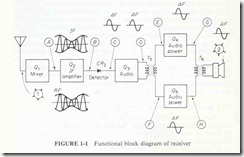
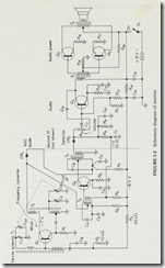
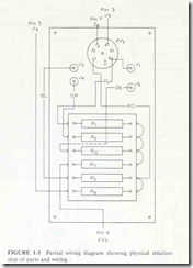
Electronic troubleshooting involves the extensive use of diagrams. These include functional block diagrams, overall schematics, and wiring diagrams, as shown in Figs. 1 1 to 1 3, respectively.
The block diagram (Fig. 1 1) shows the functional relationship of all major sections in a complete piece of equipment. The block diagram is thus the most logical source of information to use when localizing trouble to a functioning unit or section. Unfortunately, not all service literature includes a block diagram. Therefore, it may be necessary to use the overall schematic.
The schematic (Fig. 1 2) shows the functional relationship of all parts of a complete piece of equipment. Such parts include all resistors, capacitors, transistors, diodes, and so forth. Generally, the schematic presents too much information (much of it not directly related to the specific symptoms you have noted) to be of maximum value during the localizing step. If you tried to take all the details into consideration, it might become extremely difficult for you to make decisions regarding the probable trouble area. However, the schematic is very useful in later stages of the total troubleshooting effort and when a block diagram is not available.
In comparing the block diagram and the schematic during the localizing step, note that each transistor shown on the schematic (Fig. 1 2) is represented as a block on the block diagram (Fig. 1 1). This relationship is typical of most service literature.
The wiring diagram (Fig. 1 3) shows the physical relationship of all parts, as well as point to point wiring. For this reason, the wiring diagram is the least useful source of information when you are localizing trouble. However, the wiring diagram is most useful when you are locating specific parts during the repair phase of troubleshooting.
To sum up, it is logical to use a functional block diagram instead of a schematic or wiring diagram when you want to make a valid estimate of the probable trouble areas (the faulty functioning units). The use of a block diagram also permits you to use a troubleshooting technique known as bracketing. If the block diagram includes major test points, as it should in well written service literature, it will also permit you to use test equipment as an aid in narrowing the choices of probable trouble areas to a single functional unit
Isolating Trouble to a Circuit
After the trouble is localized to a single functional unit, the next step is to isolate the trouble to a circuit in the faulty unit. To do this, you consider the signal paths in the circuitry that contains the indicating instruments or other built in aids that point to abnormal performance. By concentrating on this circuitry and ignoring the circuits that produce normal indications, you narrow down or isolate the limits of the possible trouble. For example, assume that you are troubleshooting a communications set that contains a transmitter, a receiver, and a common power supply. If the receiver is operating normally but the transmitter is not, you can ignore both the receiver circuits and the common power supply circuits and concentrate on the transmitter circuits.
The isolating step in troubleshooting involves the use of test equipment such as meters, oscilloscopes, and signal generators for signal tracing and signal substitution in the suspected faulty area. By making valid educated estimates and using applicable diagrams, bracketing techniques, signal tracing, and signal substitution properly, you can systematically and logically isolate the trouble to a single defective unit. Repair techniques or tools to make necessary repairs are not used until after the specific trouble is located and verified. That is, you still do not charge into the equipment with soldering tool and screwdriver. Instead, you now try to isolate the trouble to a specific defective circuit so that it can be repaired.
Observations and decisions are made at this time, but operational evaluations are not. More specifically, the observations are now based on the indications of external test equipment used for signal tracing or signal substitution, and the decisions relate to whether these indications are normal or abnormal, based on your knowledge of how the equipment works.
Locating the Specific Trouble
Although this troubleshooting step refers only to locating the specific trouble, it includes a final analysis or review of the complete procedure and the use of repair techniques to remedy the trouble once it has been located. This final analysis will enable you to determine whether some other malfunction caused the component to become faulty or whether the component located is the actual cause of the equipment trouble.
When you are trying to locate the trouble, inspection using the senses of. sight, smell, hearing, and touch is very important. This inspection is usually performed first in order to gather information that may more quickly lead to the defective component. Among the things to look for during the inspection using the senses are burned, charred, or overheated components; arcing in the high voltage circuits; and burned out parts
In equipment where it is relatively easy to gain access to the circuitry, a rapid visual inspection should be performed first. Then, the active device (vacuum tube or transistor) can be removed from the circuit and checked. A visual inspection is always recommended as the first step for all solidstate equipment and for most vacuum tube equipment. A possible exception would be equipment in which access to circuit parts is difficult but vacuum tubes can be easily removed and tested (or substituted).
The next step in locating the specific trouble is the use of an oscilloscope to observe wave forms and a meter to measure voltages. Finally, in most cases, a meter is used to make resistance and continuity checks in order to pinpoint the defective component.
After the trouble is located, a final analysis of the complete troubleshooting procedure should be made to verify the trouble. The trouble should then be repaired, and the equipment checked out for proper operation. Note that in the service literature for home entertainment equipment such as a radio and a television set, the wave forms, voltages, and resistances are given on the schematic. For military type equipment, such information is provided in chart form along with the service literature. Either way, you must be able to use test equipment to observe the wave forms and make the measurements. For this reason, the function and use of test equipment during troubleshooting is discussed frequently throughout this boo
Developing a Systematic, Logical Troubleshooting Procedure
The development of a systematic and logical troubleshooting procedure requires:
a step-by-step approach to the problem
knowledge of the equipment
interpretation of test information
use of information gained in each step
Some technicians feel that knowledge of the equipment involves remembering past equipment failures, as well as remembering data such as the location of all test points and all adjustment procedures. This approach may be valid if you troubleshoot only one type of equipment, but is has little value in the development of a basic troubleshooting procedure.
It is true that recalling past equipment failures may be helpful, but you should not rely upon the possibility that the same trouble will be the cause of a given symptom in every case. In electronic equipment, there are many possible troubles that can give approximately the same symptom indications.
Similarly, you should never rely entirely upon your memory of adjustment procedures, test point locations, and the like in approaching any troubleshooting problem. This is one of the reasons for having service literature that contains diagrams and information about the equipment. The use of service literature and the specific types of information presented in it will be discussed more fully later in this book. The important point for you to learn now is to be a systematic, logical troubleshooter, not a memory expert.


