The nine-lead three-phase induction motor is the most popular motor for industrial use. It ranges from fractional to hundreds of horsepower. The 12lead induction motor is very similar to the nine-lead motor. Other induction motors covered are multispeed, multimode, and wound rotor motors. The synchronous motor and the brushless DC motors are also covered.
The Nine-Lead Induction Motor
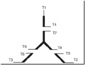
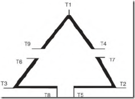
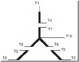
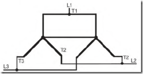
The nine-lead three-phase induction motor can be used on two voltages. It will be connected as either wye or delta. Figure 5.15 is a schematic of a ninelead wye connection. The delta connection in Fig. 5.16 is also designed for both voltages.
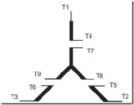
An ohmmeter can be used to determine whether the motor has a wye or delta connection (if there isn’t a connection nameplate). As the schematics show, a nine-lead wye connection has three circuits with two leads and one circuit with three leads. The delta connection has three circuits with three leads each.
Each phase (in all nine-lead dual-voltage three-phase motors) is divided into two equal circuits. Regardless of the number of poles, one-half are in each circuit. The nine-lead motor has a 2-to-l difference in its voltage rating.
FIGURE 5.15 The most common connection found in small motors in the ninelead wye connection.
FIGURE 5.16 The nine-lead delta connection is usually found in motors of 10 horsepower and above.
Each pole has the same voltage across it, whether the motor is connected high or low voltage.
A telephone keypad (Fig. 5.17) simplifies three-phase connections. Exactly one-half of each phase is connected between two keys. For example the A phase, one half of its winding is connected between keys Tl and T4 ![]() and the other half between key T7 and the blank key below it.
and the other half between key T7 and the blank key below it.
The keypad can be used as a reference for wye, delta, 12-lead, 10-lead, and wye-delta connections. The keys have windings connected to them as shown in Fig. 5.17.
A wye-connected motor will have the bottom three keys tied together (internally) to form the wye connection.
For the 10-lead connection, lead number TIO is connected to the internal wye.
FIGURE 5.18 The nine-lead wye schematic.
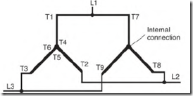
FIGURE 5.19 The low-voltage (two-wye) connection.
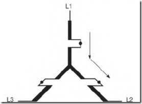
Both wye- and delta-connected motors combine the same lead numbers for high voltage. In both connections, each phase is connected in series for high voltage. In the wye connection (Fig. 5.20), a circuit from line 1 to line 2 goes through two phases.
Nine-Lead Multiple-Wye Connection with TIO
The internal wye sometimes has lead TIO connected to it. This lead is connected to T4, T5, and T6 when the motor is connected low voltage (Fig.
5.21). When the motor is connected high voltage, TIO is insulated and not used.
The purpose of TIO is to balance the voltage (and the resulting current) between the wye connections. Ideally, wye connections would have no voltage or current difference between them. (In reality, there is always some unbalance.) The most common reason for the unbalance is a slight difference in air gap around the rotor. Connecting TIO as shown in Fig. 5.22
FIGURE 5.20 The high-voltage wye connection showing where the current flows from line 1 to line 2.
FIGURE 5.21 The 10-lead dual-voltage motor.
FIGURE 5.22 Multiple wyes are often connected together internally.
equalizes the voltage and current between the two connections. The result is a better magnetic balance between the stator poles.
For example, a 30-horsepower, two-pole, multiple-wye-connected motor that powered a metal polisher had to be rewound. When the motor was rewound and reinstalled, a pattern developed on the metal, instead
of a mirror finish. The wye connections were joined, and the pattern disappeared.
Larger nine-lead motors have multiple wyes connected internally. The wyes are usually connected (internally) to a common wire, as shown in Fig.
5.22.
Thermal Protector for the Nine-Lead Wye-Connected Motor
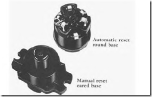
A thermal protector for the dual-voltage (230/460-volt) wye-connected threephase motor is shown in Fig. 5.23.
This protection is designed for small wye-connected motors. (The delta connection is seldom used in motors under 5 horsepower.)
FIGURE 5.23 A three-phase thennal protector. Klixon.
5
In Fig. 5.23, there are three current-monitoring heat elements. High current through these heat elements will trip open the protector’s contacts.
They are located between 1 and 4, 2 and 5, and 3 and 6.
The motor’s internal wye is connected permanently to terminals 1, 2 and 3 of the thermal protector. These leads are the ends of the phases. (In a 12-lead motor, they are labeled T 10, T 11, and T 12.)
P4, 10 5, and 10 6 bypass the heat elements. When the motor is connected low voltage, they are connected to the motor’s corresponding T leads (P4 to T4, P5 to T5, and P6 to T6). If connected high voltage, P4, P5 and P6 aren’t used and are separately insulated.
If line 1, 2, or 3 becomes open, the motor operates on single phase. (The term single-phased describes this condition.) When a motor is single-phased, its power drops to approximately one-half of its horsepower rating. The amperes increase through two of the heat elements, causing the protector’s contacts to open and disconnect all the motor’s circuits. The thermal protector uses the amperes of T7, T8, and T9 to protect the motor, whether the connection is high or low voltage.
Nine-Lead Delta Connection
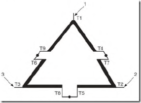
In the delta connection, T 1, T2, and T3 are the points of the delta (Fig. 5.24).
They contain the end half of one phase and the start half of the next phase. In the start half of phase A, lead Tl is connected to (the end) half of phase B.
One-half of phase A starts at Tl and ends at T4. Lead T7 completes phase A,
FIGURE 5.24 The points of the delta connection are numbered T1, T2, and T3 in the nine-lead schematic.
ending at T2. Phase C starts at T2 and ends at T5. Lead T8 completes phase C, ending at T3. Phase B starts at T3 and ends at T6. Lead T9 completes phase B, ending at Tl .
When the delta is connected low voltage, each line is connected to three motor leads. Line 1 is connected to T1, T6, and T7; line 2 to T2, T4, and T8; and line 3 to T3, T5, and T9. Figure 5.25 shows how the circuits of each phase are connected in parallel.
