Because all major appliances require electricity as an energy source, you should have a basic knowledge of the relevancy of electricity to appliance servicing. This includes a knowledge of circuit breakers or fuses when the source of electricity fails, and a knowledge of how to use simple electrical test equipment for minor electrical diagnosis.
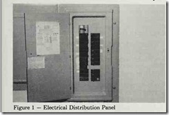
If an appliance does not appear to be receiving power, check the electrical distribution panel (circuit breaker box). (Figure 1).
Circuit Breakers
Circuit breakers consist of an electromagnet that breaks the current when its magnetic field has been stretched to its maximum allowance. Circuit breakers act as ON-OFF switches for the flow of electricity to specific electrical outlets.
Figure 1 — Electrical Distribution Panel
An electrical contractor will normally mark the switches at the time of installation to indicate which switch controls which electrical outlets. Therefore, when an appliance totally fails, check the circuit breaker box to see if the switch is OFF. Then correct the cause of the overload and manually reset the switch to the ON position.
Some older homes have fuses to serve the same purpose as circuit breakers. Fuses protect the house wiring system and appliance overloads and short circuits. Fuses are devices that consist of a metal strip that melts at a very low temperature.
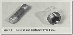
Figure 2 Screw-in and Cartridge Type Fuses
When a fuse is in proper working order, current flows through the metal. If a surge of current occurs due to current overload or a short circuit, the flow of electricity through the metal strip generates heat to melt the metal strip, thus breaking the current and creating an open circuit. Then you must replace the fuse. Fuses are of a screw-in or plug type, and the cartridge type (Figure 2). Usually screw-in fuses are used in 120-volt lines, while cartridge fuses are used in 240-volt applications.
Test equipment can be an important aid in finding the cause of trouble in a failed home appliance. The main purpose of testing is to find out whether current is flowing through a particular component without being “leaky ‘ or “open.” The normal procedure is to disconnect the component from the line, connect the leads from the test equipment to the component terminals, plug in or switch ON the test equipment to the component terminals, and then plug in or switch ON the test equipment to get a reading on the dial.
Homemade Electrical Test Cord
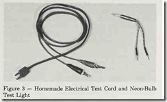
For minor electrical diagnosing and troubleshooting, you need two inexpensive pieces of test equipment: a homemade electrical test cord (Figure 3) and a neon-bulb test light. You can make the electrical test cord from an old discarded appliance cord. You simply attach two alligator clips to the exposed wires at the end of the cord. You can use this cord to make live electrical checks and to check refrigerator compressors. The neon-bulb tester is used for making live voltage checks. This tester is a very simple device that is available in most hardware stores. It cannot be used for checking electrical components of an appliance. The test cord will be discussed in more detail later in this service guide.
Figure 3 — Homemade Electrical Test Cord and Neon-Bulb Test Light
Professional appliance technicians use a variety of sophisticated testing tools to determine power breaks and to analyze an appliance for defects. You would probably use this test equipment only if you had a greater-than-normal aptitude to challenge difficult repair problems. However, the following simple testing devices may be helpful to you:
Testing Devices Volt/Ohmmeter , Ammeter And Wattmeter
Volt/Ohmmeter (Figure 4) – A volt/ohmmeter set on the VOLTAGE scale measures the voltage across an electrical line and determines if the proper voltage is available. The OHMMETER scale of the volt/ohmmeter allows you to locate breaks in circuits and make continuity checks to switches, thermostats, elements, motors, capacitors, etc.
The volt/ohmmeter is mentioned several times throughout this service guide as a necessary tool to test home appliance components. If you do not have this test equipment, you can purchase it for less than $15 in do-it-yourself centers and electronic stores. These economical versions are capable of performing almost any check and test that is mentioned in this service guide. The volt/ohmmeter is very easy to use, and there is no reason to be afraid of using it. In fact, when making a continuity check between one contact to another on an appliance, you always unplug the appliance first. Voltage or electrical checks would damage the meter movement of the volt/ohmmeter.
In checking a suspected defective switch, for example, you unplug the appliance and set the volt/ohmmeter selector switch to the RX-1 scale. Place one probe of the volt/ohrnmeter on one terminal of the switch and place the remaining probe to the other terminal of the switch. With the switch depressed (pushed in), you should see continuity, or O ohms, (full meter deflection) on the volt/ohmmeter scale. This procedure will be used many times throughout this service guide.
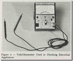 Figure 4 Volt/Ohmmeter Used in Checking Electrical Appliances
Figure 5 — Ammeter Used in Checking Electrical Appliances
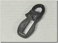
Ammeter (Figure 5) – Amperage is the current at which electricity flows through a conductor. An ammeter measures the current flow. It is effective in checking appliance motors and refrigerator compressors.
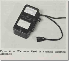
Wattmeter (Figure 6) – Wattage is the product of volts times amperes. A wattmeter measures the frequency at which sixty-cycle alternating current changes direction 120 times each second. This determines how effectively the mechanical system of an appliance is functioning.
Figure 6 Wattmeter Used in Checking Electrical Appliances
Testing Switches
Switches – You check switches with a volt/ohmmeter to test for electrical continuity across the terminals of each switch setting. You always disconnect the appliance before checking any switches with the volt/ohmmeter. Live voltage checks will damage the meter movement.
Testing Overload Protectors
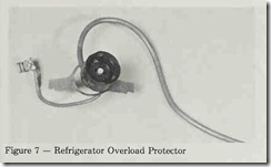
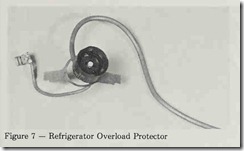
Overload Protectors (Figure 7) – An overload protector is a bi-metalic device that consists of two types of metals. One metal expands more than the other as heat is applied or as they are cooled. As the temperature changes, the uneven expansion of the metal causes them to bend. As they bend, the contact points in the bi-metal will make or break the circuit. In the case of a refrigerator, the overload protector is attached to the compressor housing and senses unusual temperature conditions as well as excessive electrical loads, thus breaking the circuit.
Figure 7 — Refrigerator Overload Protector
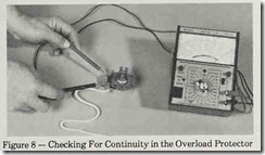
Overload protectors can be checked with a jumper wire and a volt/ohmmeter. When using the jumper wire method, you place the jumper between terminals one and two of the protector. If the compressor will run with the wire jumper in place but fails when jumper is removed, a faulty overload protector is indicated. A safer (and easier) way to check a protector is to use a volt/ohmmeter. Across terminals one and two; there should be continuity (meter swing to 0 ohms) if the protector is good, and no continuity (no meter swing) if the protector is defective. (Figure 8).
Figure 8 Checking For Continuity in the Overload Protector
Figure 9 — Refrigerator Thermostat
Testing Thermostats
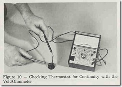
Thermostats (Figure 9) – In a refrigerator, the thermostat opens the circuit and shuts off the compressor when the preset temperature of the thermostat is reached. When the thermostat contacts close, the compressor starts up again and continues running until the unit has again reached the desired temperature. This process maintains a constant coolness inside the refrigerator. The thermostat can be checked with the volt/ohmmeter by removing the thermostat from the refrigerator cabinet and warming the sensing bulb with your hand. You should achieve continuity (0 ohms on the RX-1 scale) with the ohmmeter across the thermostat terminals (Figure 10).
Figure 10 — Checking Thermostat for Continuity with the Volt/Ohmmeter
Testing Start Capacitors
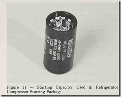
Start Capacitors – Most compressors in refrigerators, freezers, air conditioners and- a variety of common electric motors must have high starting torque in order to begin rotation under load. To obtain this torque, a starting capacitor (Figure 11) is placed in series with the start winding circuit of the electric motor. When the start winding is engaged by electricity, the capacitor builds up voltage and then discharges via the same winding in the form of a power surge.
This power surge from the capacitor gives the electric motor or compressor motor the added torque it needs to begin running under a loaded condition.
Figure 11 Starting Capacitor Used in Refrigerator Compressor Starting Package
WARNING: A charged capacitor is extremely dangerous. A capacitor will hold a charge indefinitely even while not in use. If a person were to touch the terminals of a charged capacitor, the build-up of high voltage would give him a shock that could result in bodily injury or be fatal.
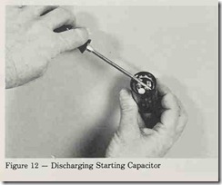
You discharge a capacitor by shorting the two terminals together (Figure 12). This can be done by using a screwdriver with an insulated handle. The best method is to use a 20k ohm (20,000) resistor that is rated at 2 watts or higher. This method eliminates the hazard of high-voltage arc that will occur when discharging a start or run capacitor using the “screwdriver short” method.
Figure 12 Discharging Starting Capacitor
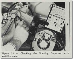
After the capacitor has been fully discharged, check the capacitor by using the following procedure and the volt/ohmmeter. Set volt/ ohmmeter to the RX10 scale and connect the leads to the capacitor. The meter should swing full scale momentarily before starting a slow motion in the opposite direction as the capacitor discharges. If the meter fails to swing full scale on contact with the terminals, the capacitor is open and must be replaced. Also, if the volt/ohmmeter remains in the full-scale position and does not begin to move in the opposite direction, the capacitor is shorted and must be replaced (Figure 13).
Figure 13 – Checking the Starting Capacitor with Volt/Ohmmeter
Testing Relay
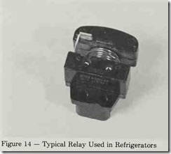
Relays (Figure 14) – The function of relays used in refrigerators is to energize the start winding in the compressor motor until the unit comes “up to speed.” At this point, the relay breaks the circuit to the start winding and the run winding takes over, allowing the motor to continue to run. If the relay is not dropping out or sticking, the compressor runs hotter than usual and, in most cases, shuts off via the overload protection circuit described earlier. A relay is on the verge of failure if the unit is “struggling” – trying to start several times before actually beginning to run. When you find this condition, replace the relay. Low-line voltages will cause the refrigerator relay to ”chatter.” This does not happen very often, but when it does you must find the low-voltage source.
Figure 14 Typical Relay Used in Refrigerators
Testing Solenoids
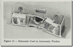
Solenoids (Figure 15) – The purpose of solenoids, used mainly in the automatic washer, is to convert electrical energy into mechanical energy. A solenoid is basically a wire coil that produces a magnetic field. When energized by electrical current, it acts like a magnet. A plunger assembly inside the coil is pulled into it by magnetism. When the solenoid is de-energized, the plunger moves out of the coil by gravity, or by spring pull. There are several applications of solenoids in home appliances, including water inlet valve, bleach dispensing, end-of-cycle signaling, lid latch control and agitation control.
Figure 15 — Solenoids Used in Automatic Washer
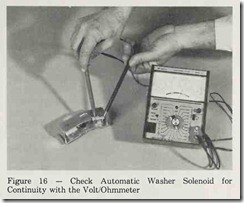
Check solenoids for defect by using the volt/ohmmeter. Place the volt/ohmmeter probes between the two terminals, with the meter set on RX 10 scale or RX 100. The meter should show a half-scale or less deflection, which indicates the solenoid coil is good (Figure 16). No meter movement indicates an open solenoid, and the defective component should be replaced.
Figure 16 – Check Automatic Washer Solenoid for Continuity with the Volt/Ohmmeter
Testing Timers
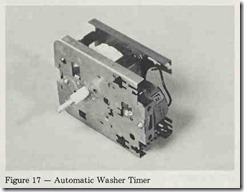
Timers (Figure 17) – You can check timers in the automatic washer and some refrigerators with a volt/ohmmeter across the contact points in the same manner as described for switches. Timers frequently have dirty contacts that fail to make a circuit. In this case, you should clean the timer contacts with a small file.
Figure 17 -Automatic Washer Timer
