LINEAR CIRCUITS
There are two basic types of circuits, linear and digital. Digital circuits are covered in the next chapter. Linear circuits are those circuits that process analog signals. Recall that analog signals are those that vary smoothly and continuously over time in contrast to pulse and digital signals that are voltages that switch off and on very fast. Analog signals are like sine waves, voice signals, video signals, radio waves, and voltages from sensors like a temperature transducer. DC, either a constant value of voltage or one that is varying, is also an analog signal.
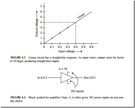
A linear circuit is one whose output is proportional to its input. See Figure 4.1. Its so-called response is a straight line or what a mathematician would call a linear function. The best example of this is the amplifier where its output is proportional to its input so that it accurately reproduces the input faithfully but at a higher voltage or power level. In the figure, with 0.4 volt input you get 4 volt output. That means the amplifier has a gain of 10. Linear circuits do not distort the signal. This chapter covers linear circuits with most of the emphasis on amplifiers since that is the largest category of linear circuits. And as it turns out, most other types of linear circuits are just amplifiers connected in different ways to give different processing results.
Amplifiers
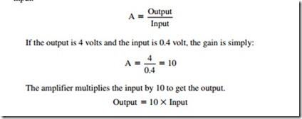
The basic block diagram symbol for an amplifier is a triangle. See Figure 4.2. It has an input and an output. Amplifiers also have one or more DC inputs as well. This DC from a battery or other power supply is what powers the circuit
and it is this DC that is ultimately converted into the new, larger output signal. In most cases the DC inputs are not shown in a block diagram. The amplifier processes the input to create an output of the same shape but at a larger amplitude.
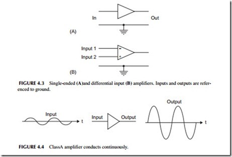
The primary characteristic of any amplifier is its gain. The gain (usually represented by A) is simply a number equal to the ratio of the output to the input.
Classifying Amplifiers
The amplifier is the most common linear circuit. There are so many different types of amplifiers that we divide them up into different types to distinguish one from another. And there are multiple ways of doing this. Here are the most common.
Small Signal versus Large Signal
Small signal amplifiers are those that, as the name implies, only amplify small signals which are those roughly below about 1 volt. Small signal amplifiers amplify millivolt, microvolt, or nanovolt signals. Large signal amplifiers amplify larger signals and typically amplify the power of a signal rather than the voltage. These are called power amplifiers (PAs).
Frequency Classification
Amplifiers are also categorized by the frequency of the signals they amplify. Some examples are DC amplifiers, audio frequency (AF) amplifiers, intermediate frequency (IF) amplifiers, video amplifiers, radio frequency (RF) amplifiers, and microwave amplifiers.
Configuration Classification
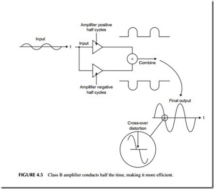
The two main configurations are single-ended and differential. A single-ended amplifier is one in which the input and output are referenced to a common ground. These amplifiers have two inputs, one is the signal and the other is ground. See Figure 4.3A. Normally only the input is shown as the ground is just assumed to be there.
A differential amplifier has two inputs as Figure 4.3B shows. These are usually called the inverting (-) and the non-inverting (+) inputs. Both inputs are referenced to ground. The amplifier is called a differential amplifier because it actually takes the mathematical difference between the two inputs and amplifies the result. One input is subtracted from another, then the differ- ence is amplified by the gain A. The formula for this operation is:
Differential amplifiers have one neat feature in that any signal common to both inputs like noise is automatically canceled out. This feature is widely taken advantage of in very small signal amplifiers used in memory chips and high gain amplifiers that amplify small signals from sensors. Noise that is picked up simultaneously on both inputs simply subtracts itself out without bothering the desired small difference signal.
Classification by Class of Operation
One way to categorize amplifiers is to designate the conduction of the transistors in the amplifiers. The primary classes are A, B, AB, C, D, E, and F. There are a few others but these are the most common. Class A amplifiers conduct continuously. We say that the amplification occurs over the full 360 degrees of a sine wave cycle. See Figure 4.4. Note: The small t on the wave- forms means time as the voltage is varying over time.
Class B amplifier transistors only conduct for half a cycle or 180 degrees of a sine wave. See Figure 4.5. Such an amplifier seems useless since it distorts the signal. But if you combine two transistors, one to amplify positive cycles and the other to amplify negative cycles, then combine the two, the complete wave is amplified. Such an amplifier is called a push pull amplifier. The benefit of this arrangement is that the circuit is more efficient.
Class AB amplifiers are a variation of the class B. Class B amps do add a little distortion to the signal around the point where the sine wave crosses zero. This is caused by the transistors not turning on and off precisely at the zero point. This glitch shown in Figure 4.5 is called crossover distortion. To get rid of that, class AB amplifiers allow some small current to flow continuously. The result is less distortion but a little less efficiency.
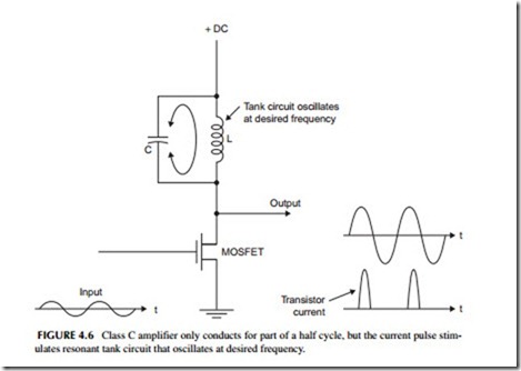
Class C amplifiers are for RF signals and are usually power amplifiers. They only allow the transistor to conduct for less than 180 degrees of a sine wave input, usually 90 to 150 degrees. It produces massive distortion. However, the amplifier output is made up of an inductor and capacitor (LC) tuned circuit that oscillates at the operating frequency and removes the distortion. These amplifiers are very efficient.
In a class C amplifier the MOSFET acts like a switch that is turned off and on by the input signal, usually a sine wave. See Figure 4.6. When the MOSFET is on the capacitor charges up to the DC supply voltage and current flows in the inductor creating a surrounding magnetic field. When the transistor turns off, the inductor and capacitor begin to exchange energy and set up an oscillation at the resonant frequency of the LC circuit. This is called a tank circuit. The result is that the energy stored in the tank circuit produces the amplified sine wave output.
Another way of looking at this is that the transistor switch distorts the input creating a pulse waveform that contains lots of harmonics. The tank circuit acts like a selective band-pass filter that lets the fundamental sine wave pass while the harmonics are filtered out.
Don ’t forget the Fourier theory and harmonics. Remember that a harmonic is an integer multiple of a fundamental sine wave. If the fundamental sine wave is 20MHz, the 2nd harmonic is 40MHz, the 3rd harmonic is 60MHz, the 4th harmonic is 80 MHz, and so on. Any non-sine wave signal, like a half sine wave, square wave, or pulse is said to be made up of the fundamental sine wave added to multiple harmonics. A distorted sine wave has the fundamental sine wave in it but also harmonics. This concept is called the Fourier theory after the French mathematician.
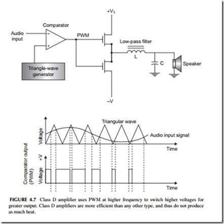
Class D amplifiers are a special class called a switching amplifier. It is made up of transistor switches rather than a real linear amplifier. This amplifier chops the input analog signal into high-frequency pulses with a varying width. See Figure 4.7. This process is called pulse width modulation (PWM).
The sine wave audio signal to be amplified is sent to one input of a special amplifier called a comparator along with a higher-frequency triangle wave. The comparator output switches when the triangle wave and sine wave values are equal. The resulting PWM signal is then fed to MOSFET switches to make the signal bigger. The higher amplitude output it then filtered back into an analog signal by a low-pass filter made up of a capacitor and inductor. Most class D amplifiers are audio power amplifiers whose load is a speaker or headphone. For low power less than a few watts, all the circuitry is in a single IC. For higher power, the MOSFETs are larger external devices.
The big benefit of switching amplifiers is that for a given output power they are very efficient. Whereas a class AB amplifier may only be 20 to 30% efficient, the class D is over 90% efficient. This means that the amplifier can be smaller and use less power and dissipates less heat. Class D amplifiers are great for portable battery-operated devices like MP3 players and cell phones.
Classes E and F are special switching amplifier variations used at RF frequencies only. Like the class C amplifier, they use LC circuits to filter out the harmonics they produce. They are very efficient.
Operational Amplifiers
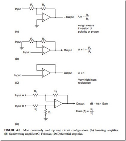
There are many special types of amplifiers. The most widely used is the operational amplifier or op amp. This is a versatile high-gain DC differential amplifier that can be configured with external resistors, capacitors, diodes, etc. to perform a wide variety of amplification functions. The op amp may be the most widely used type of amplifier because of its versatility.
Figure 4.8 shows the most common op amp configurations. In most cases, the resistors are external to the IC amplifier. Note that the gain is determined by the values of the external resistors. Note formulas for gain (A).
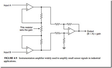
A variation of the op amp is the instrumentation amp. See Figure 4.9. It is a combination of multiple op amps that make it very useful in industrial applications such as amplifying small signals from sensors. Again the gain is deter- mined by the resistor values. You can make this amplifier from individual op amps but usually you just buy it as a single integrated circuit. The external resistor sets the gain.
A variable or programmable gain amplifier is one whose gain can be con- trolled from an external DC input.
Amplifier Specifications
While you really do not need to know much about what the circuitry in an amplifier IC is, you do need to understand the specifications. Here are the most common specifications to look for.
As mentioned before, gain is the primary amplifier characteristic. It is usually a voltage or power ratio, depending on the type of amplifier.
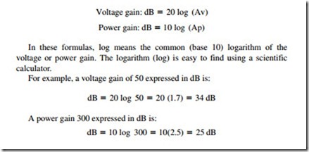
Many amplifiers have their gain expressed in decibels (dB). A dB is a gain measurement based on a logarithmic scale rather than a linear scale. This has the advantage of being able to express large and small gains in smaller numbers.
And gains of multiple stages can be added rather than multiplied. To calculate dB gains you used these formulas:
Input Impedance
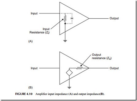
Input impedance is the load seen by the signal source to the amplifier. It is usually resistive but typically also has some capacitance across it. Figure 4.10A shows an equivalent circuit of an amplifier. Note the input resistance. That is the input impedance. It may be as high as several megohms or could be as low
as, say, 50 ohms. Usually the higher the better for voltage amplifiers but not for power amplifiers.
Output Impedance
Amplifiers act as signal generating sources because they essentially just create a new higher voltage or higher power signal with the same shape as the input. They appear as a signal generator to the next circuit or load. Figure 4.10B shows the amplifier as a generator shaped as a diamond. It has an internal impedance or series resistance called the output impedance. It is not a real resistor but it is there and it appears in series with whatever load is connected which may be another amplifier or something else.
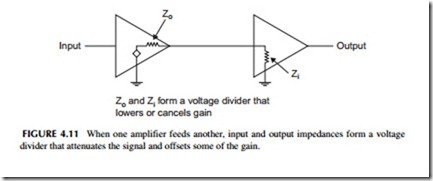
Figure 4.11 shows the amplifier connected to another amplifier. Note that the output impedance for amplifier A2 and the load form a voltage divider so some of the amplification is lost to the voltage divider effect. The input impedance of A2 is the load for the output impedance of A1.
Cascading Amplifiers
If an amplifier does not have enough gain, then multiple amplifiers can be cascaded one after the other to give the needed gain. One amplifier amplifies the output of the next and so on. See Figure 4.12. To calculate the overall gain of an amplifier you just multiply the gains as shown in the figure. This procedure assumes that one amplifier does not load the next. That is, the output impedance of each amplifier is assumed to be zero and the input impedance of the next amplifier is assumed to be infinite. That way, there is no voltage divider effect that lowers the gain.
