bread boarding
A breadboard is a platform for building a prototype of an electronic circuit. In the early days of radio in the Navy, radio operators would nail copper wires or terminal strips to a wooden board (often the bread
cutting board from the Mess deck) and solder electronic components to them. Sometimes they would glue a paper schematic diagram to act as a guide to locating terminals. Then they would solder components and wires over the symbols on the schematic.
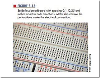
Breadboarding is essential to proving that a circuit design works. Breadboard is the term that is now used for all types of devices used for prototyping. In 1971, Ronald J. Portugal of EI Instruments Inc. designed the solderless breadboard most commonly used to- day. It is usually manufactured from white plastic, with perforation and numerous metal clips to plug wires and components in (Figure 5-13). The spacing be- tween the perforations is typically 0.1 inch (0.25 cm), the same as the spacing of the leads on an integrated circuit.
Solderless breadboards were developed to allow circuits to be assembled and altered quickly without soldering. The circuit is constructed using the actual components that would be used in assembling the circuit on a PCB. A PCB is not easy to modify once the circuits are assembled. PCBs only allow minor alterations following final assembly, such as changing resistor or capacitor values or replacing integrated circuits with the same type of devices.
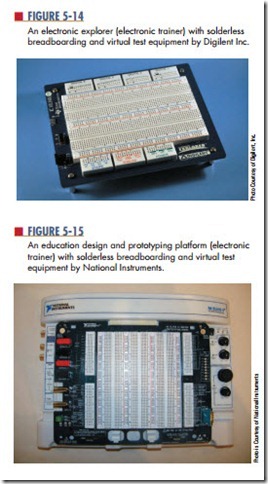
There are many electronic trainers constructed using solderless breadboards. Two such electronic trainers are Digilent’s Electronic Explorer (Figure 5-14) and National Instruments’ education design and prototyping platform—ELVIS (Figure 5-15). Both of these units include virtual test equipment that dis- plays signals on a computer.
Computer programs such as National Instruments’ Multisim, New Wave Concepts’ Circuit Wizard, Cadence’s OrCAD PSpice, and Spectrum Software’s Micro-Cap 7 allow virtual breadboarding, or testing of a circuit and troubleshooting using virtual test equipment. Several of these programs shows the current flow in a circuit to aid in understanding how a circuit performs. These programs are the wave of the future.
Questions
1. What function does breadboarding serve?
2. Why were solderless breadboards developed?
3. Why should a circuit be breadboarded?
4. What are some computer programs that allow virtual breadboarding?
5. Why is a program such as Circuit Wizard important to the study of electronics?

