NOISE REDUCTION
Any sound which is an unwanted signal is noise. This noise can be kept to extremely low levels, but when sound is transformed into an electrical signal, noise can be added to it in ways over which we have very little control.
If we play a blank tape we find that the noise level is very low. The noise originates mainly in the recording process. It is, in fact, the erase and bias signals which arrange the magnetism of the tape particles at random so as to produce the effect of noise on replay. Part of this noise can be reduced by good design of the oscillator which produces the erase bias signal, and by good processing of materials used for the production of the tape.
NOISE REDUCTION
If we record on wider sections of tape, we find that the signal-to-noise ratio is much better. For example, when a cassette is recorded mono on the same equipment is much better as compared to record stereo cassettes. The difference is caused by the random nature of the noise. If we compare two strips of tape, one recorded to double the width of the other, we would expect that because twice as many particles are magnetised by the signal in the wider strip, the replay signal would have twice the amplitude from the wider strip as from the narrow strip. But the noise from the wider strip is not twice as great, but nearer to 1.4 times as great (where 1.4 is approximately equal to ![]() ). This arises because noise is not a signal of definite shape, and particles in the tape may line up with their magnetism opposing each other just as readily as they line up with their magnetism assisting.
). This arises because noise is not a signal of definite shape, and particles in the tape may line up with their magnetism opposing each other just as readily as they line up with their magnetism assisting.
The problem of signal-to-noise ratio in tape recording is simply solved by using wider sections of tape, so that a full width tape (1/4 in) should have a very good signal-to-noise ratio. Dividing a full width tape into two sections for a half track stereo tape reduces the signal-to-noise ratio in each channel, but the results are still acceptable. Further reducing the recorded width by half again to give 4-track stereo (two-halves of stereo recording) degrades the signal to noise ratio still further And another reduction by half of width, needed to fit two sets of stereo channels on a cassette tape, has resulted in noise levels which are unacceptable when compared with the results obtainable from FM radio or from discs. It is worth noting that all disc recordings start by being tape recording.
Despite considerable improvements in tape materials and in the design of erase/bias oscillators, the noise content of a cassette tape is too high unless some sort of noise reduction process is carried out on the signal at some stage. Several methods of noise reduction have been devised. No high-quality cassette deck or recorder lacks a noise reduction system.
The type of noise found from different signal sources varies because of the different causes of the noise. Some receiver noise is white meaning, that it contains frequencies spread all over the audio range, with no preferred frequencies. The noise from discs is not white, but has a range of frequencies related to the speed of the disc past the recording cutter and the replay stylus. Noise of this sort can be shifted to a lower frequency by making the disc revolve at a low speed. Fortunately, noise in lower frequency ranges is not particularly offensive to the ear, so that change over from 78 rpm discs to 33 rpm discs caused a very great reduction in the apparent noise as heard by the listener. Reducing the speed of tape does not have any effect, however the noise remains obstinately in the same frequency range, which, unfortunately, happens to be the range of frequencies to which the ear is most sensitive, with the peak amount of noise at around 4.5 to 5.0 kHz.
In a few low priced cassette machines, a button marked noise reduction simply cuts the level of frequencies, above about 2.5 kHz, so reducing the noise and also removing much of the signal. The signal frequency presents a problem for much of our useful musical information occurs in the same range as the noise and any attempt to remove these frequencies makes for a replayed signal of intolerably low quality.
PRE-EMPHASIS AND DE-EMPHASIS
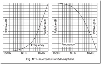
In frequency modulation the modulation or sideband frequencies often extend outward to as much as 15 kHz. This provides a much broader audio range than is usually found in conventional A.M. broadcasting. The higher audio frequencies produced by the program source are generally weaker than the lower audio frequencies, and thus produce a smaller frequency deviation in the carrier. In the normal transmitting process a certain amount of interference is encountered, such as atmospherics, which have little effect on the large amplitude low-frequency signals. However, with regard to the weak high-frequency signals, the signal-to- noise ratio is low. To correct this condition, the Federal Communication Commission (FCC) standards call for a pre-emphasis network. This consists of a high-pass filter having a time constant of 75 micro seconds. The pre-emphasis at the FM transimtter provides for an audio gain of 1 at 50 Hz, to a gain of 7 at 15 kHz. From 50 to 500 Hz, the rise is very slight, but from there it increases rapidly. Thus the net effect of pre- emphasis is to increase the signal-to-noise ratio at the higher audio frequencies. Standard pre-emphasis and de-emphasis curves are illustrated in Fig. 12.1.
If the pre-emphasis were not corrected at the receiver, the sound signal would have a heavy treble effect. To compensate for this, the FM receiver employs a de-emphasis network, a low-pass filter. As in the case of the high-pass filter, the low-pass filter in the de-emphasis network also has a time constant of 75 micro-seconds.
The de-emphasis network can be placed in any one of the several places in the receiver, but practice finds it located at the output of the FM detector circuit. It is anRC filter that shunts the higher audio frequencies to ground while affecting the lower audio frequencies to a lesser extent. The overall effect of the pre-emphasis and de-emphasis networks is to provide a noise free signal at the output of the receiver that is a true replica of the sound signal at the studio.
This is the solution to the problem of noise in FM radio, adopted almost from the beginning of f.m. broadcasting. This type of noise reduction, so easily applied to broadcasting, requires that every receiver shall be fitted with the correct de-emphasis filter. The system is a double-ended one, because both transmitted and received signals have to be processed by similar circuits. Unfortunately the frequency range of the filters is not internationally standardised. In addition, the upper frequency limits of FM transmitters have been improved so much over the years, that the amount of treble boost now needed at the highest frequencies is excessive, and causes distortion at the transmitter.
A similar problem of excessive boost makes the pre-emphasis and de-emphasis methods unsuitable for cassette recorders. Because of the low tape speed, and the limits of size of head gap, recording of the high frequencies is difficult enough, needing a considerable boost to the high frequencies in the recording amplifier just to obtain a reasonable level response at the output. The extra boost which would be needed for pre- emphasis makes the scheme impossible because the filter system used makes the boost greater at the higher frequencies, and the amplitude of the signal would lead to over-recording and distortion.
COMPANDERS
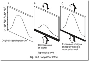
The professional solution to the problems of limited dynamic range and poor signal to noise ratio has been overcome by the use of compression and expansion circuits called companders, Fig. 12.2. The compressor circuit boosts weak signals relative to strong signals by a preset amount, so that the range of signal amplitude is less than it was in the original signal. The compressed signal is then recorded with the peak just reaching the peak permitted recording level, so that the weakest signals are at a level well above the noise level.
On replay, the signals are passed through the expander section, which exactly reverses the process, restoring the original range, and also reducing the noise caused by the recording process to very low levels.
If the compressing and expanding circuits exactly match each other, excellent results are obtained. In practice, all recorded or transmitted signals are compressed to some extent, but the circuits used for compression are non-standardised so that we carry out the expansion correctly at the receiver or replay stages. In addition, the circuits used for compression and expansion in professional work are extremely complicated taking into account every requirement of recording.
Simple compression circuits may, far from reducing noise, even increase it. A good example is the use of automatic level controls in cheap cassette recorders, since these circuits are simple compressors. With no sound in, the gain of the recording amplifier is adjusted to maximum, so that the noise signal in the input circuits is amplified and recorded as if it were a signal. When a true signal appears, the gain is reduced so as to keep the signal near the peak recording level. The effect on replay is of music at an almost constant sound level with a variable level of noise, the noise suddenly becoming very loud during what should be the quiet passages of music. This is most undesirable, rather just the opposite of what is needed.
NOISE REDUCTION SYSTEMS
The following noise reduction systems are widely used.
1. Dolby A system 2. Dolby B system
3. Philips DNL system 4. dbx system
5. Burwen system
Of all the noise reduction systems, the only two which have been applied widely to cassette recorders are the Dolby system and the Philips Dynamic Noise Limiter (DNL) system. The only factor common to them is that they seek to reduce noise particularly in quiet passages of signal where noise is most noticeable, and in the frequency ranges to which the ear is most sensitive. Though the DNL system has some applications in playback of older recordings, the Dolby process, being a double-ended system, is more effective, much more widely used, and likely to be applied to FM stereo transmitters and to disc recordings also (Figs. 12.3 and 12.4).
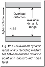
Dynamic range in tape recording is limited at one end by tape saturation level and at the other end by tape hiss. Increasing the signal input above a pre- determined level will result in servere distortion without giving an increase of output level. Reducing the input level will not affect the hiss, which is of constant amplitude and independent of the incoming signal level.
Tape hiss is present on all recordings but it will not always be audible. An example is pop music which is compressed into a narrow dynamic range, has a high average level and is subjectively loud.
When the dynamic range is wide, as with the solo piano, the recording level is set to give full modulation on peaks, the quietest passages will be comparable with the hiss level. If the hiss level becomes higher than the music, the music is masked by it; similarly when the music level exceeds that of the hiss, the hiss is masked.
To render the tape hiss unobtrusive it is necessary to reduce it in level compared with the quietest signals to be reproduced (most of which will be in the high and mid-frequency range). One way of doing this is to apply a given amount of high frequency pre-emphasis during recording, similar to that used for FM transmission, and to use a corresponding de-emphasis on replay. The objections to this approach have already been discussed.
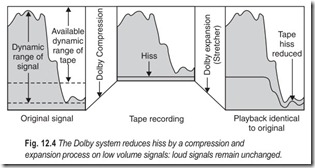
What is required is a processing circuit on record, the response characteristic of which will vary with both the frequency and the amplitude of the applied signal. As the signal level progressively falls below a given datum so that processor will selectively increase the gain of the system to compensate; the amount of compensation will depend on the level and frequency of the incoming signal. On replay an inversion of the process will restore the original dynamics and frequency range, and the previously emphasised low level signals will be attenuated together with the hiss.
The above principle, with a number of elegant refinements, is the basis of the noise reduction system devised by Dr. Ray Dolby. As the hiss problem is particularly acute in low speed machines using thin tapes, all top quality cassette recorders incorporate Dolby B circuitry. The original Dolby A system is intended for professional use and operates on the entire frequency spectrum, not just the highs. The Dolby B system is a consumer product system, the high frequency outputs of the pre-amplifier are amplified during recording. During playback, these frequencies are correspondingly attenuated. Since the hiss and general noise of recordings occur in the high-frequency spectrum, these too are attenuated, on the order of 10–50 dB.
The available dynamic range of any recording medium, Fig. 12.3, lies between overload distortion point and background noise level.
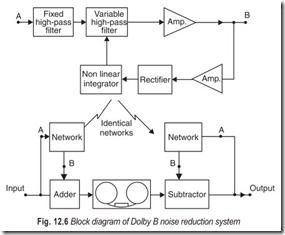
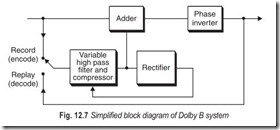
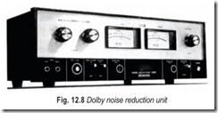
Figure 12.4 illustrates the reduction of tape hiss by Dolby B process. Fig. 12.5 shows the Dolby B’s effect on frequency response during recording and playback. Fig. 12.6 shows how the Dolby system works. Fig. 12.7 is a simplified block diagram which shows the Dolby principle more clearly. We can see that there is a main program chain and a side chain. The side chain has a compressor preceded by a high-pass filter. In the encode (record) mode signals below a given threshold are boosted by the compressor and added to the main chain. The degree of boost is dependent on the control voltage fed back from the rectifier to the variable filter. When the control voltage is zero, maximum boost is applied. The control voltage increases with increasing signal level and when the control voltage is maximum, no boost is applied. After processing, the composite signal is recorded in the conventional manner. Fig. 12.8 illustrates Teac’s AN-180 Dolby noise reduction unit. Dolby eliminates unwanted tape hiss and noise.
On decode (replay) the circuit operates with the processor in a feedback loop. This time a phase inverted signal is fed to the filter/compressor and the resultant is added to the main chain. Because of the phase inversion this addition is in fact a cancellation of the earlier processing and the original signal is retrieved with its dynamics and frequency range intact, but with the hiss highly attenuated. It should be noted that the hiss will only be reduced if it is a product of the record/replay process. Any hiss on incoming program material will be interpreted as music and processed accordingly and faithfully reproduced.
The dbx noise reduction system uses dynamic range compression to encode the signal before recording, and a matched expander to restore original dynamics on playback. The compression and expansion factor is 2:1, and is linear in dB over a 110 dB range. A 20 dB change in program is recorded as a 10 dB change on the tape. Thus, a recording medium capable of only 55 dB signal to noise ratio can record and reproduce the full dynamic range of live music, which often exceeds 100 dB. Noise reduction here is of the order of 30 dB.
The Burwen system works with orginal program material which has not been modified during recording. The fundamental principle is that noise which is quite audible during the absence of recorded material is effectively masked by high-frequency material at moderate or loud volume; consequently any circuitry which can de-emphasize high frequencies, when there is no high-frequency program material to mask the hiss, will also eliminate the important noise component. Because it is designed to work with material that has not been previously encoded, the Burwen system is of particular significance to owners of old 78 rpm records. Noise reduction here is of the order of 6 to 8 dBm but that is without significant loss of high frequency program material.
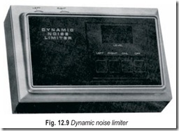
Dynamic Noise Limiter is illustrated in Fig. 12.9. Connected between the signal source and amplifier it has 5-pin DIN input and output sockets. The DNL suppresses hiss without reducing the natural brilliance of reproduction. In fact it has the effect of increasing signal-to-noise ratio.
EXERCISES
Descriptive Questions
1. What is the need for noise reduction systems?
2. Explain the different sources of noise in tape recording.
3. Give a brief explanation of the different types of noise reduction systems.
4. What is the difference between Dolby A and Dolby B?
Multiple Choice Questions
1. The problem of signal-to-noise ratio is simply solved by using,
(a) wider sections of tape (b) narrower sections of tape
2. White noise contains frequencies spread
(a) all over the audio range
(b) over a restricted portion of the audio range
3. Noise in lower frequency range is
(a) particularly offensive to the human ear
(b) not particularly offensive to the human ear
4. The net effect of pre-emphasis is to
(a) increase the signal-to-noise ratio at the higher audio frequencies
(b) decrease the signal-to-noise ratio at the higher audio frequencies
5. Dynamic range in tape recording is limited by
(a) tape hiss (b) tape saturation
(c) (a) and (b) (d) neither (a) nor (b)
6. Dolby A system operates on
(a) the entire frequency spectrum (b) just the highs
Fill in the Blanks
1. In a……………………………………..system both the transmitted and received signals have to be processed by similar circuits.
2. Companders are……………………………………..cum ……………………………………..circuits.
3. The expander circuit reverses the process of …………………………………….. circuit.
4. Noise reduction circuits seek to reduce noise, particularly in …………………………………….. passages of signal.
5. The compression and expansion factor in a dbx noise reduction system is ………………………………………
6. The Burwen system works with original program material which has not been …………………………………….. during recording.
ANSWERS
Multiple Choice Questions
1. (a) 2. (a) 3. (b) 4. (a) 5. (c) 6. (a)
Fill in the Blanks |
||
|
1. double-ended 4. quiet |
2. compressor, expander 5. 2:1 |
3. compressor 6. modified |
