Tensile Testing

Tensile Testing

The Tensile Test

A tensile test is one in which a force is applied to a specimen of a material in increments and the corresponding extension of the specimen noted. The process may be continued until the specimen breaks into two parts and this is called testing to destruction. The testing is usually carried out using a universal testing machine that can apply either tensile or compressive forces to a specimen in small, accurately measured steps. British Standard 18 gives the standard procedure for such a test. Test specimens of a material are made to standard shapes and sizes and two typical test pieces are shown in Figure 24.1. The results of a tensile test may be plotted on a load/extension graph and a typical graph for a mild steel specimen is shown in Figure 24.2.

(i) Between A and B is the region in which Hooke’s law applies and stress is directly proportional to strain. The gradient of AB is used when determining Young’s modulus of elasticity (see Chapter 23).

(ii) Point B is the limit of proportionality and is the point at which stress is no longer proportional to strain when a further load is applied.

(iii) Point C is the elastic limit and a specimen loaded to this point will effectively return to its original length when the load is removed, i.e.

there is negligible permanent extension.

(iv) Point D is called the yield point and at this point there is a sudden extension with no increase in load. The yield stress of the material is given by:

image

(v) Between points D and E extension takes place over the whole gauge length of the specimen.

(vi) Point E gives the maximum load which can be applied to the specimen and is used to determine the ultimate tensile strength (UTS) of the specimen (often just called the tensile strength)

image

(vii) Between points E and F the cross-sectional area of the specimen decreases, usually about half way between the ends, and a waist or neck is formed before fracture.

image

The percentage reduction in area provides information about the malleability of the material (see Chapter 23).

The value of stress at point F is greater than at point E since although the load on the specimen is decreasing as the extension increases, the cross-sectional area is also reducing.

(viii) At point F the specimen fractures.

(ix) Distance GH is called the permanent elongation and

image

For example, a rectangular zinc specimen is subjected to a tensile test and the data from the test is shown below. Width of specimen 40 mm; breadth of specimen 2.5 mm; gauge length 120 mm.

image

Fracture occurs when the extension is 5.0 mm and the maximum load recorded is 38.5 kN.

A load/extension graph is shown in Figure 24.3

The limit of proportionality occurs at point P on the graph, where the initial gradient of the graph starts to change. This point has a load value of 26.5 kN.

Stress at the limit of proportionality is given by:

image

image


Simple Machines

Simple Machines

Machines

A machine is a device that can change the magnitude or line of action, or both magnitude and line of action of a force. A simple machine usually amplifies an input force, called the effort, to give a larger output force, called the load. Some typical examples of simple machines include pulley systems, screw- jacks, gear systems and lever systems.

Force Ratio, Movement Ratio and Efficiency

The force ratio or mechanical advantage is defined as the ratio of load to effort, i.e.

image

Since both load and effort are measured in newtons, force ratio is a ratio of the same units and thus is a dimension-less quantity.

The movement ratio or velocity ratio is defined as the ratio of the distance moved by the effort to the distance moved by the load, i.e.

image

Since the numerator and denominator are both measured in metres, movement ratio is a ratio of the same units and thus is a dimension-less quantity.

The efficiency of a simple machine is defined as the ratio of the force ratio to the movement ratio, i.e.

image

Since the numerator and denominator are both dimension-less quantities, efficiency is a imension-less quantity. It is usually expressed as a percent- age, thus:

image

Due to the effects of friction and inertia associated with the movement of any object, some of the input energy to a machine is converted into heat and losses occur. Since losses occur, the energy output of a machine is less than the energy input, thus the mechanical efficiency of any machine cannot reach 100%.

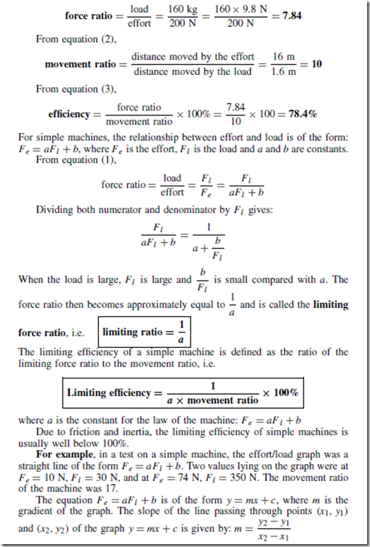
For example, a simple machine raises a load of 160 kg through a distance of 1.6 m. The effort applied to the machine is 200 N and moves through a distance of 16 m.

From equation (1),

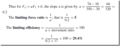
image

image

Pulleys

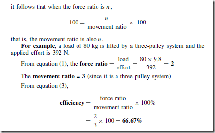
A pulley system is a simple machine. A single-pulley system, shown in Figure 22.1(a), changes the line of action of the effort, but does not change the magnitude of the force.

A two-pulley system, shown in Figure 22.1(b), changes both the line of action and the magnitude of the force. Theoretically, each of the ropes marked (i) and (ii) share the load equally, thus the theoretical effort is only half of the load, i.e. the theoretical force ratio is 2. In practice the actual force ratio is less than 2 due to losses.

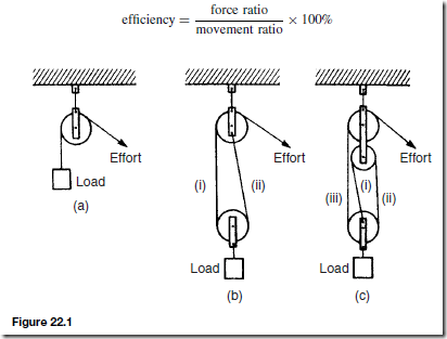
A three-pulley system is shown in Figure 22.1(c). Each of the ropes marked (i), (ii) and (iii) carry one-third of the load, thus the theoretical force ratio is 3. In general, for a multiple pulley system having a total of n pulleys, the theoretical force ratio is n. Since the theoretical efficiency of a pulley system (neglecting losses) is 100 and since from equation (3),

image

image

The Screw-jack

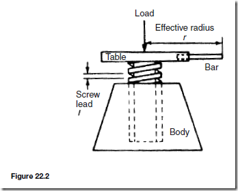
A simple screw-jack is shown in Figure 22.2 and is a simple machine since it changes both the magnitude and the line of action of a force.

The screw of the table of the jack is located in a fixed nut in the body of the jack. As the table is rotated by means of a bar, it raises or lowers a load placed on the table. For a single-start thread, as shown, for one complete revolution of the table, the effort moves through a distance 2nr, and the load

image

moves through a distance equal to the lead of the screw, say, l

image

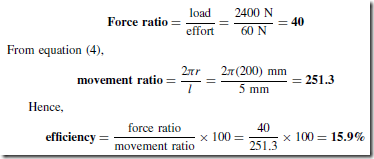
For example, a screw-jack is used to support the axle of a car, the load on it being 2.4 kN. The screw jack has an effort of effective radius 200 mm and a single-start square thread, having a lead of 5 mm. If an effort of 60 N is required to raise the car axle:

image

Gear Trains

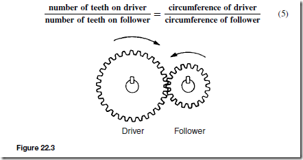
A simple gear train is used to transmit rotary motion and can change both the magnitude and the line of action of a force, hence is a simple machine. The gear train shown in Figure 22.3 consists of spur gears and has an effort applied to one gear, called the driver, and a load applied to the other gear, called the follower.

In such a system, the teeth on the wheels are so spaced that they exactly fill the circumference with a whole number of identical teeth, and the teeth on the driver and follower mesh without interference. Under these conditions, the number of teeth on the driver and follower are in direct proportion to the circumference of these wheels, i.e.

image

If there are, say, 40 teeth on the driver and 20 teeth on the follower then the follower makes two revolutions for each revolution of the driver. In general:

image

It follows from equation (6) that the speeds of the wheels in a gear train are inversely proportional to the number of teeth. The ratio of the speed of the driver wheel to that of the follower is the movement ratio, i.e.

image

When the same direction of rotation is required on both the driver and the follower an idler wheel is used as shown in Figure 22.4

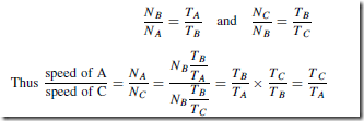
Let the driver, idler, and follower be A, B and C, respectively, and let N be the speed of rotation and T be the number of teeth. Then from equation (7),

image

This shows that the movement ratio is independent of the idler, only the

direction of the follower being altered.

A compound gear train is shown in Figure 22.5, in which gear wheels B and C are fixed to the same shaft and hence NB = NC

image

image

For example, a compound gear train consists of a driver gear A, having 40 teeth, engaging with gear B, having 160 teeth. Attached to the same shaft as B, gear C has 48 teeth and meshes with gear D on the output shaft, having 96 teeth.

image

Levers

A lever can alter both the magnitude and the line of action of a force and is thus classed as a simple machine. There are three types or orders of levers, as shown in Figure 22.6

A lever of the first order has the fulcrum placed between the effort and the load, as shown in Figure 22.6(a).

image

A lever of the second order has the load placed between the effort and the fulcrum, as shown in Figure 22.6(b).

A lever of the third order has the effort applied between the load and the fulcrum, as shown in Figure 22.6(c).

Problems on levers can largely be solved by applying the principle of moments (see Chapter 12). Thus for the lever shown in Figure 22.6(a), when the lever is in equilibrium,

image


Simple Machines

Simple Machines

Machines

A machine is a device that can change the magnitude or line of action, or both magnitude and line of action of a force. A simple machine usually amplifies an input force, called the effort, to give a larger output force, called the load. Some typical examples of simple machines include pulley systems, screw- jacks, gear systems and lever systems.

Force Ratio, Movement Ratio and Efficiency

The force ratio or mechanical advantage is defined as the ratio of load to effort, i.e.

image

Since both load and effort are measured in newtons, force ratio is a ratio of the same units and thus is a dimension-less quantity.

The movement ratio or velocity ratio is defined as the ratio of the distance moved by the effort to the distance moved by the load, i.e.

image

Since the numerator and denominator are both measured in metres, movement ratio is a ratio of the same units and thus is a dimension-less quantity.

The efficiency of a simple machine is defined as the ratio of the force ratio to the movement ratio, i.e.

image

Since the numerator and denominator are both dimension-less quantities, efficiency is a imension-less quantity. It is usually expressed as a percent- age, thus:

image

Due to the effects of friction and inertia associated with the movement of any object, some of the input energy to a machine is converted into heat and losses occur. Since losses occur, the energy output of a machine is less than the energy input, thus the mechanical efficiency of any machine cannot reach 100%.

For example, a simple machine raises a load of 160 kg through a distance of 1.6 m. The effort applied to the machine is 200 N and moves through a distance of 16 m.

From equation (1),

image

image

Pulleys

A pulley system is a simple machine. A single-pulley system, shown in Figure 22.1(a), changes the line of action of the effort, but does not change the magnitude of the force.

A two-pulley system, shown in Figure 22.1(b), changes both the line of action and the magnitude of the force. Theoretically, each of the ropes marked (i) and (ii) share the load equally, thus the theoretical effort is only half of the load, i.e. the theoretical force ratio is 2. In practice the actual force ratio is less than 2 due to losses.

A three-pulley system is shown in Figure 22.1(c). Each of the ropes marked (i), (ii) and (iii) carry one-third of the load, thus the theoretical force ratio is 3. In general, for a multiple pulley system having a total of n pulleys, the theoretical force ratio is n. Since the theoretical efficiency of a pulley system (neglecting losses) is 100 and since from equation (3),

image

image

The Screw-jack

A simple screw-jack is shown in Figure 22.2 and is a simple machine since it changes both the magnitude and the line of action of a force.

The screw of the table of the jack is located in a fixed nut in the body of the jack. As the table is rotated by means of a bar, it raises or lowers a load placed on the table. For a single-start thread, as shown, for one complete revolution of the table, the effort moves through a distance 2nr, and the load

image

moves through a distance equal to the lead of the screw, say, l

image

For example, a screw-jack is used to support the axle of a car, the load on it being 2.4 kN. The screw jack has an effort of effective radius 200 mm and a single-start square thread, having a lead of 5 mm. If an effort of 60 N is required to raise the car axle:

image

Gear Trains

A simple gear train is used to transmit rotary motion and can change both the magnitude and the line of action of a force, hence is a simple machine. The gear train shown in Figure 22.3 consists of spur gears and has an effort applied to one gear, called the driver, and a load applied to the other gear, called the follower.

In such a system, the teeth on the wheels are so spaced that they exactly fill the circumference with a whole number of identical teeth, and the teeth on the driver and follower mesh without interference. Under these conditions, the number of teeth on the driver and follower are in direct proportion to the circumference of these wheels, i.e.

image

If there are, say, 40 teeth on the driver and 20 teeth on the follower then the follower makes two revolutions for each revolution of the driver. In general:

image

It follows from equation (6) that the speeds of the wheels in a gear train are inversely proportional to the number of teeth. The ratio of the speed of the driver wheel to that of the follower is the movement ratio, i.e.

image

When the same direction of rotation is required on both the driver and the follower an idler wheel is used as shown in Figure 22.4

Let the driver, idler, and follower be A, B and C, respectively, and let N be the speed of rotation and T be the number of teeth. Then from equation (7),

image

This shows that the movement ratio is independent of the idler, only the

direction of the follower being altered.

A compound gear train is shown in Figure 22.5, in which gear wheels B and C are fixed to the same shaft and hence NB = NC

image

image

For example, a compound gear train consists of a driver gear A, having 40 teeth, engaging with gear B, having 160 teeth. Attached to the same shaft as B, gear C has 48 teeth and meshes with gear D on the output shaft, having 96 teeth.

image

Levers

A lever can alter both the magnitude and the line of action of a force and is thus classed as a simple machine. There are three types or orders of levers, as shown in Figure 22.6

A lever of the first order has the fulcrum placed between the effort and the load, as shown in Figure 22.6(a).

image

A lever of the second order has the load placed between the effort and the fulcrum, as shown in Figure 22.6(b).

A lever of the third order has the effort applied between the load and the fulcrum, as shown in Figure 22.6(c).

Problems on levers can largely be solved by applying the principle of moments (see Chapter 12). Thus for the lever shown in Figure 22.6(a), when the lever is in equilibrium,

image


The Effects of Forces on Materials.

The Effects of Forces on Materials

Introduction

A force exerted on a body can cause a change in either the shape or the motion of the body. The unit of force is the newton, N.

No solid body is perfectly rigid and when forces are applied to it, changes in dimensions occur. Such changes are not always perceptible to the human eye since they are so small. For example, the span of a bridge will sag under the weight of a vehicle and a spanner will bend slightly when tightening a nut. It is important for engineers and designers to appreciate the effects of forces on materials, together with their mechanical properties.

The three main types of mechanical force that can act on a body are:

(i) tensile, (ii) compressive, and (iii) shear

Tensile Force

Tension is a force that tends to stretch a material, as shown in Figure 23.1. Examples include:

(i) the rope or cable of a crane carrying a load is in tension

(ii) rubber bands, when stretched, are in tension

(iii) a bolt; when a nut is tightened, a bolt is under tension

A tensile force, i.e. one producing tension, increases the length of the material on which it acts.

Compressive Force

Compression is a force that tends to squeeze or crush a material, as shown in Figure 23.2. Examples include:

(i) a pillar supporting a bridge is in compression

(ii) the sole of a shoe is in compression

(iii) the jib of a crane is in compression

image

A compressive force, i.e. one producing compression, will decrease the length of the material on which it acts.

Shear Force

Shear is a force that tends to slide one face of the material over an adjacent face. Examples include:

(i) a rivet holding two plates together is in shear if a tensile force is applied between the plates — as shown in Figure 23.3

(ii) a guillotine cutting sheet metal, or garden shears, each provide a shear

force

(iii) a horizontal beam is subject to shear force

(iv) transmission joints on cars are subject to shear forces

A shear force can cause a material to bend, slide or twist.

image

Stress

Forces acting on a material cause a change in dimensions and the material is said to be in a state of stress. Stress is the ratio of the applied force F to cross-sectional area A of the material. The symbol used for tensile and compressive stress is a (Greek letter sigma). The unit of stress is the Pascal,

image

where F is the force in newtons and A is the cross-sectional area in square metres.

For tensile and compressive forces, the cross-sectional area is that which is at right angles to the direction of the force.

For example, a rectangular bar having a cross-sectional area of 75 mm2 has a tensile force of 15 kN applied to it. Then

image

Strain

The fractional change in a dimension of a material produced by a force is called the strain. For a tensile or compressive force, strain is the ratio of the change of length to the original length. The symbol used for strain is ε (Greek epsilon). For a material of length l metres which changes in length by an amount x metres when subjected to stress,

image

Shear Stress and Strain

For a shear force, the shear strain is equal toimageforce area , where the area is that which is parallel to the direction of the force. The symbol for shear stress is the Greek letter tau, r

image

For any metal the modulus of rigidity G is approximately 0.4 of the modulus of elasticity E.

Torsional Stress and Strain

With reference to Figure 23.5:image

image

For example, a hollow shaft of length 2.4 m, has external and internal diameters of 100 mm and 80 mm. The torque the shaft can transmit if the maximum permissible shear stress is 45 MPa is given by:

image

Elasticity and Elastic Limit

Elasticity is the ability of a material to return to its original shape and size on the removal of external forces.

Plasticity is the property of a material of being permanently deformed by a force without breaking. Thus if a material does not return to the original shape, it is said to be plastic.

Within certain load limits, mild steel, copper, polythene and rubber are examples of elastic materials; lead and plasticine are examples of plastic materials.

If a tensile force applied to a uniform bar of mild steel is gradually increased and the corresponding extension of the bar is measured, then pro- vided the applied force is not too large, a graph depicting these results is likely to be as shown in Figure 23.6. Since the graph is a straight line, extension is directly proportional to the applied force.

If the applied force is large, it is found that the material no longer returns to its original length when the force is removed. The material is then said to have passed its elastic limit and the resulting graph of force/extension is no longer a straight line. Stress, a D A , from above, and since, for a particular bar, area A can be considered as a constant, then F a. x clip_image039Strain ε D l , from above, and since for a particular bar l is constant, then x / ε. Hence for stress applied to a material below the elastic limit a graph of stress/strain will be as shown in Figure 23.7, and is a similar shape to the force/extension graph of Figure 23.6

image

Hooke’s Law

Hooke’s law states:

Within the elastic limit, the extension of a material is proportional to the applied force

It follows, from above, that:

Within the elastic limit of a material, the strain produced is directly proportional to the stress producing it

Young’s modulus of elasticity

Within the elastic limit, stress ˛ strain, hence

stress = (a constant) x strain

This constant of proportionality is called Young’s modulus of elasticity and is given the symbol E. The value of E may be determined from the gradient of the straight line portion of the stress/strain graph. The dimensions of E are pascals (the same as for stress, since strain is dimension-less).

image

Some typical values for Young’s modulus of elasticity, E, include: Aluminium 70 GPa (i.e. 70 ð 109 Pa), brass 90 GPa, copper 96 GPa, diamond 1200 GPa, mild steel 210 GPa, lead 18 GPa, tungsten 410 GPa, cast iron 110 GPa, zinc 85 GPa

Stiffness

A material having a large value of Young’s modulus is said to have a high value of stiffness, where stiffness is defined as:

image

image

Ductility, Brittleness and Malleability

Ductility is the ability of a material to be plastically deformed by elongation, without fracture. This is a property that enables a material to be drawn out into wires. For ductile materials such as mild steel, copper and gold, large extensions can result before fracture occurs with increasing tensile force. Ductile materials usually have a percentage elongation value of about 15% or more.

Brittleness is the property of a material manifested by fracture without appreciable prior plastic deformation. Brittleness is a lack of ductility, and brittle materials such as cast iron, glass, concrete, brick and ceramics, have virtually no plastic stage, the elastic stage being followed by immediate fracture. Little or no ‘waist’ occurs before fracture in a brittle material undergoing a tensile test.

Malleability is the property of a material whereby it can be shaped when cold by hammering or rolling. A malleable material is capable of undergoing plastic deformation without fracture. Examples of malleable materials include lead, gold, putty and mild steel.


Potential and Kinetic Energy

Potential and Kinetic Energy

Introduction

Mechanical engineering is concerned principally with two kinds of energy, potential energy and kinetic energy.

Potential Energy

Potential energy is energy due to the position of the body. The force exerted on a mass of m kg is mg N (where g D 9.81 m/s2, the acceleration due to gravity). When the mass is lifted vertically through a height h m above some datum level, the work done is given by: force ð distance D (mg)(h) J. This work done is stored as potential energy in the mass.

image

(the potential energy at the datum level being taken as zero).

For example, if a car of mass 800 kg is climbing an incline at 10° to the horizontal, the increase in potential energy of the car as it moves a distance of 50 m up the incline is determined as follows:

image

Kinetic Energy

Kinetic energy is the energy due to the motion of a body. Suppose a force F acts on an object of mass m originally at rest (i.e. u D 0) and accelerates it to a velocity v in a distance s:

image

image

Principle of Conservation of Energy

Energy may be converted from one form to another. The principle of conservation of energy states that the total amount of energy remains the same in such conversions, i.e. energy cannot be created or destroyed.

In mechanics, the potential energy possessed by a body is frequently converted into kinetic energy, and vice versa. When a mass is falling freely, its potential energy decreases as it loses height, and its kinetic energy increases as its velocity increases. Ignoring air frictional losses, at all times:

potential energy + kinetic energy = a constant

If friction is present, then work is done overcoming the resistance due to friction and this is dissipated as heat. Then,

image

Kinetic energy is not always conserved in collisions. Collisions in which kinetic energy is conserved (i.e. stays the same) are called elastic collisions, and those in which it is not conserved are termed inelastic collisions.

Kinetic Energy of Rotation

The tangential velocity v of a particle of mass m moving at an angular velocity ω rad/s at a radius r metres (see Figure 21.2) is given by:

image

image

If all the masses were concentrated at the radius of gyration it would give the same moment of inertia as the actual system.

For example, a system consists of three small masses rotating at the same speed about a fixed axis; the masses and their radii of rotation are: 16 g at 256 mm, 23 g at 192 mm and 31 g at 176 mm.

image

Flywheels

The function of a flywheel is to restrict fluctuations of speed by absorbing and releasing large quantities of kinetic energy for small speed variations.

To do this they require large moments of inertia and to avoid excessive mass they need to have radii of gyration as large as possible. Most of the mass of a flywheel is usually in its rim.

For example, a cast iron flywheel is required to release 2.10 kJ of kinetic energy when its speed falls from 3020 rev/min to 3010 rev/min. The moment of inertia of the flywheel is assumed to be concentrated in its rim which is to be of rectangular section, the external and internal diameters being 670 mm and 600 mm. The radius of gyration of the rim may be assumed to be its mean radius. Taking the density of cast iron as 7800 kg/m3 , the required width for the flywheel is determined as follows:

image


Potential and Kinetic Energy

Potential and Kinetic Energy

Introduction

Mechanical engineering is concerned principally with two kinds of energy, potential energy and kinetic energy.

Potential Energy

Potential energy is energy due to the position of the body. The force exerted on a mass of m kg is mg N (where g D 9.81 m/s2, the acceleration due to gravity). When the mass is lifted vertically through a height h m above some datum level, the work done is given by: force ð distance D (mg)(h) J. This work done is stored as potential energy in the mass.

image

(the potential energy at the datum level being taken as zero).

For example, if a car of mass 800 kg is climbing an incline at 10° to the horizontal, the increase in potential energy of the car as it moves a distance of 50 m up the incline is determined as follows:

image

Kinetic Energy

Kinetic energy is the energy due to the motion of a body. Suppose a force F acts on an object of mass m originally at rest (i.e. u D 0) and accelerates it to a velocity v in a distance s:

image

image

Principle of Conservation of Energy

Energy may be converted from one form to another. The principle of conservation of energy states that the total amount of energy remains the same in such conversions, i.e. energy cannot be created or destroyed.

In mechanics, the potential energy possessed by a body is frequently converted into kinetic energy, and vice versa. When a mass is falling freely, its potential energy decreases as it loses height, and its kinetic energy increases as its velocity increases. Ignoring air frictional losses, at all times:

potential energy + kinetic energy = a constant

If friction is present, then work is done overcoming the resistance due to friction and this is dissipated as heat. Then,

image

Kinetic energy is not always conserved in collisions. Collisions in which kinetic energy is conserved (i.e. stays the same) are called elastic collisions, and those in which it is not conserved are termed inelastic collisions.

Kinetic Energy of Rotation

The tangential velocity v of a particle of mass m moving at an angular velocity ω rad/s at a radius r metres (see Figure 21.2) is given by:

image

image

If all the masses were concentrated at the radius of gyration it would give the same moment of inertia as the actual system.

For example, a system consists of three small masses rotating at the same speed about a fixed axis; the masses and their radii of rotation are: 16 g at 256 mm, 23 g at 192 mm and 31 g at 176 mm.

image

Flywheels

The function of a flywheel is to restrict fluctuations of speed by absorbing and releasing large quantities of kinetic energy for small speed variations.

To do this they require large moments of inertia and to avoid excessive mass they need to have radii of gyration as large as possible. Most of the mass of a flywheel is usually in its rim.

For example, a cast iron flywheel is required to release 2.10 kJ of kinetic energy when its speed falls from 3020 rev/min to 3010 rev/min. The moment of inertia of the flywheel is assumed to be concentrated in its rim which is to be of rectangular section, the external and internal diameters being 670 mm and 600 mm. The radius of gyration of the rim may be assumed to be its mean radius. Taking the density of cast iron as 7800 kg/m3 , the required width for the flywheel is determined as follows:

image


Work, Energy and Power

 Work, Energy and Power

Work

If a body moves as a result of a force being applied to it, the force is said to do work on the body. The amount of work done is the product of the applied force and the distance, i.e.

image

The unit of work is the joule, J, which is defined as the amount of work done when a force of 1 newton acts for a distance of 1 m in the direction of the force. Thus, 1 J = 1 Nm

If a graph is plotted of experimental values of force (on the vertical axis) against distance moved (on the horizontal axis) a force/distance graph or work diagram is produced. The area under the graph represents the work done.

For example, a constant force of 20 N used to raise a load a height of 8 m may be represented on a force/distance graph as shown in Figure 20.1. The area under the graph, shown shaded, represents the work done. Hence

image

In another example, a spring extended by 20 mm by a force of 500 N may be represented by the work diagram shown in Figure 20.2, where

image

It is shown in chapter 9 that force D mass ð acceleration, and that if an object is dropped from a height it has a constant acceleration of around 9.81 m/s2.

For example, if a mass of 8 kg is lifted vertically 4 m, the work done is given by:

image

The work done by a variable force may be found by determining the area enclosed by the force/distance graph using an approximate method (such as the mid-ordinate rule)

Energy

Energy is the capacity, or ability, to do work. The unit of energy is the joule, the same as for work. Energy is expended when work is done. There are several forms of energy and these include:

(i) Mechanical energy (ii) Heat or thermal energy

(iii) Electrical energy (iv) Chemical energy

(v) Nuclear energy (vi) Light energy

(vii) Sound energy

Energy may be converted from one form to another. The principle of conservation of energy states that the total amount of energy remains the same in such conversions, i.e. energy cannot be created or destroyed.

Some examples of energy conversions include:

(i) Mechanical energy is converted to electrical energy by a generator

(ii) Electrical energy is converted to mechanical energy by a motor

(iii) Heat energy is converted to mechanical energy by a steam engine

(iv) Mechanical energy is converted to heat energy by friction

(v) Heat energy is converted to electrical energy by a solar cell

(vi) Electrical energy is converted to heat energy by an electric fire

(vii) Heat energy is converted to chemical energy by living plants

(viii) Chemical energy is converted to heat energy by burning fuels

(ix) Heat energy is converted to electrical energy by a thermocouple

(x) Chemical energy is converted to electrical energy by batteries

(xi) Electrical energy is converted to light energy by a light bulb

(xii) Sound energy is converted to electrical energy by a microphone.

(xiii) Electrical energy is converted to chemical energy by electrolysis.

Efficiency is defined as the ratio of the useful output energy to the input energy. The symbol for efficiency is 1 (Greek letter eta). Hence

image

Efficiency has no units and is often stated as a percentage. A perfect machine would have an efficiency of 100%. However, all machines have an efficiency lower than this due to friction and other losses.

For example, if the input energy to a motor is 1000 J and the output energy is 800 J then the efficiency is:

image

In another example, if a machine exerts a force of 200 N in lifting a mass through a height of 6 m, the efficiency of the machine if 2 kJ of energy are supplied to it is calculated as follows:

image

Power

Power is a measure of the rate at which work is done or at which energy is converted from one form to another.

image

The unit of power is the watt, W, where 1 watt is equal to 1 joule per second. The watt is a small unit for many purposes and a larger unit called the kilowatt, kW, is used, where 1 kW = 1000 W

The power output of a motor that does 120 kJ of work in 30 s is thus given by

image

For example, if a lorry is travelling at a constant velocity of 72 km/h and the force resisting motion is 800 N, then the tractive power necessary to keep the lorry moving at this speed is given by:

image


Light Rays

Light Rays

Introduction

Light is an electromagnetic wave (see page 66) and the straight line paths followed by very narrow beams of light, along which light energy travels, are called rays.

The behaviour of light rays may be investigated by using a ray-box. This consists merely of a lamp in a box containing a narrow slit which emits rays of light.

Light always travels in straight lines although its direction can be changed by reflection or refraction.

Reflection of Light

Figure 19.1 shows a ray of light, called the incident ray, striking a plane mirror at O, and making an angle i with the normal, which is a line drawn at right angles to the mirror at O.

i is called the angle of incidence. r is called the angle of reflection. There are two laws of reflection:

(i) The angle of incidence is equal to the angle of reflection (i.e. i D r in Figure 19.1)

(ii) The incident ray, the normal at the point of incidence and the reflected

ray all lie in the same plane.

A Simple Periscope

A simple periscope arrangement is shown in Figure 19.2. A ray of light from O strikes a plane mirror at an angle of 45° at point P. Since from the laws

image

of reflection the angle of incidence i is equal to the angle of reflection r then i = r = 45°. Thus angle OPQ = 90° and the light is reflected through 90° . The ray then strikes another mirror at 45° at point Q. Thus a = b = 45° , angle PQR = 90° and the light ray is again reflected through 90°. Thus the light from O finally travels in the direction QR, which is parallel to OP, but displaced by the distance PQ. The arrangement thus acts as a periscope.

Refraction of Light

When a ray of light passes from one medium to another the light undergoes a change in direction. This displacement of light rays is called refraction.

Figure 19.3 shows the path of a ray of light as it passes through a parallel- sided glass block. The incident ray AB that has an angle of incidence i enters the glass block at B. The direction of the ray changes to BC such that the angle

r is less than angle i. r is called the angle of refraction. When the ray emerges from the glass at C the direction changes to CD, angle r0 being greater than i0 . The final emerging ray CD is parallel to the incident ray AB.

Lenses

In general, when entering a more dense medium from a less dense medium, light is refracted towards the normal and when it passes from a dense to a less dense medium it is refracted away from the normal. Lenses are pieces of glass or other transparent material with a spherical surface on one or both sides. When light is passed through a lens it is refracted.

Lenses are used in spectacles, magnifying glasses and microscopes, telescopes, cameras and projectors.

There are a number of different shaped lenses and two of the most common are shown in Figure 19.4.

Figure 19.4(a) shows a bi-convex lens, so called since both its surfaces curve outwards. Figure 19.4(b) shows a bi-concave lens, so called since both

image

of its surfaces curve inwards. The line passing through the centre of curvature of the lens surface is called the principal axis.

Figure 19.5 shows a number of parallel rays of light passing through a bi-convex lens. They are seen to converge at a point F on the principal axis.

Figure 19.6 shows parallel rays of light passing through a bi-concave lens.

They are seen to diverge such that they appear to come from a point F, which lies between the source of light and the lens, on the principal axis.

In both Figure 19.5 and Figure 19.6, F is called the principal focus or the focal point, and the distance from F to the centre of the lens is called the focal length of the lens.

An image is the point from which reflected rays of light entering the eye appear to have originated. If the rays actually pass through the point then a real image is formed. Such images can be formed on a screen. Figure 19.7

illustrates how the eye collects rays from an object after reflection from a plane mirror. To the eye, the rays appear to come from behind the mirror and the eye sees what seems to be an image of the object as far behind the mirror as the object is in front. Such an image is called a virtual image and this type cannot be shown on a screen.

Lenses are important since they form images when an object is placed at an appropriate distance from the lens.

image

image

Bi-convex Lenses and their Applications

(i) Figure 19.8 shows an object O (a source of light) at a distance of more than twice the focal length from the lens. To determine the position and size of the image, two rays only are drawn, one parallel with the principal axis and the other passing through the centre of the lens. The image, I, produced is real, inverted (i.e. upside down), smaller than the object (i.e. diminished) and at a distance between one and two times the focal length from the lens. This arrangement is used in a camera.

(ii) Figure 19.9 shows an object O at a distance of twice the focal length from the lens. This arrangement is used in a photocopier.

(iii) Figure 19.10 shows an object O at a distance of between one and two focal lengths from the lens. The image I is real, inverted, magnified (i.e. greater than the object) and at a distance of more than twice the focal length from the lens. This arrangement is used in a projector

(iv) Figure 19.11 shows an object O at the focal length of the lens. After passing through the lens the rays are parallel. Thus the image I can be considered as being found at infinity and being real, inverted and very much magnified. This arrangement is used in a spotlight.

image

image

(v) Figure 19.12 shows an object O lying inside the focal length of the lens. The image I is virtual, since the rays of light only appear to come from it, is on the same side of the lens as the object, is upright and magnified. This arrangement is used in a magnifying glass.

Bi-concave Lenses

For a bi-concave lens, as shown in Figure 19.13, the object O can be any distance from the lens and the image I formed is virtual, upright, diminished and is found on the same side of the lens as the object. This arrangement is used in some types of spectacles.

A Compound Microscope

A compound microscope is able to give large magnification by the use of two (or more) lenses. An object O is placed outside the focal length Fo of a bi-convex lens, called the objective lens (since it is near to the object), as shown in Figure 19.14. This produces a real, inverted, magnified image I1.

image

This image then acts as the object for the eyepiece lens (i.e. the lens nearest the eye), and falls inside the focal length Fo of the lens. The eyepiece lens then produces a magnified, virtual, inverted image I2 as shown in Figure 19.14.

A Simple Projector

A simple projector arrangement is shown in Figure 19.15 and consists of a source of light and two-lens system. L is a brilliant source of light, such as a tungsten filament. One lens system, called the condenser (usually consisting of two converging lenses as shown), is used to produce an intense illumination of the object AB, which is a slide transparency or film. The second lens, called the projection lens, is used to form a magnified, real, upright image of the illuminated object on a distant screen CD.