Très Chic: Threads for Special Occasions , Dressing for semiformal to formal affairs , Commemorating the holidays in style , Understanding what to wear and what not to wear to weddings and Shopping guide for special event clothing

Très Chic: Threads for Special Occasions

In This Chapter

▶ Dressing for semiformal to formal affairs

▶ Commemorating the holidays in style

▶ Understanding what to wear and what not to wear to weddings

▶ Shopping guide for special event clothing

If you’ve been reading this book straight through, you know by now that I want you to feel like a 10 anytime you leave the house. When you head to the market, you should look put together in your sweats or jeans. When you’re off to work, you should look and feel like you’re ready for a productive day. And when you’re getting ready for a special occasion, well, the fabulous you better be ready for a fabulous night out!

In this chapter, I explain the differences between white tie, black tie, and cocktail attire; how to dress for holidays and weddings; and how to shop for whatever else you may have coming up that falls in between!

Evening Wear

How many times have you received an invitation in the mail and said to your- self, “What am I going to wear to this!?” Well, we’ve all been there, excited for an occasion but less than thrilled about deciding what to wear to it — especially when you don’t quite know the fashion rules that apply to the different types of events, be they white tie, black tie, cocktail, or something in between. It can be confusing and the rules are a bit subjective, but I steer you in the right direction in this section.

In real estate, the key phrase is location, location, location. When deciding what to wear for an evening out, the same phrase applies. When picking out your attire, you have to keep in mind where you’re going and who your audience is.

Dressing for a cocktail party

Cocktails anyone? Now we’re talking my language! A cocktail party can celebrate many different occasions. Some people hold cocktail parties just for the fun of it while others center this type of party around birthdays, anniversaries, promotions, and so on. A typical cocktail party usually starts somewhere between 6:00 and 9:00 p.m. and lasts for a couple of hours. Light food — a selection of hors d’oeuvres, for example — is served, but not a sit-down dinner, hence the name cocktail party!

What should you wear to a cocktail party? This type of event is much more casual than a black-tie event but dressier than a dinner out with friends. The following can clear up any confusion you have about cocktail attire.

Dress length: If you wear a dress, cocktail length is the way to go (obviously). That means that your dress should hit your leg right below the knee, as shown in Figure 11-1. But because there are no strict rules when it comes to a cocktail party, if you have fab legs, feel free to wear a shorter dress. How short should you go? With a cocktail party, you have a lot of leeway. How short you can go depends on a few things. Is it business or purely social? When it’s business, it’s still safe to wear something above the knee as long as it’s not a mini, but if you have doubts, always err on the longer side. If it’s purely social, use your judgment. In this case you can get away with something shorter.

clip_image007

Figure 11-1: A dress that hits right below the knee is always a safe bet for a cocktail party.

For cocktail parties, you aren’t limited to cocktail dresses. If you feel more comfortable in a two-piece outfit, go that route. For example, a sequin skirt paired with a beautiful cashmere sweater is perfect cocktail attire (see Figure 11-2). You can also go with a beautiful pair of slacks and a dressy blouse. Wear what you look best in. “Cocktail attire” is a looser term than “black tie.” You’ve got room to play around, so play!

Color: What is the appropriate color to wear to a cocktail party? Well, that depends on where the function is and on what day of the week. A little black dress always works. But if you’re always in your LBD, try to get away from that. If you’re heading to a work cocktail party at 6:00 p.m. on a Tuesday, I suggest sticking with more neutral tones in a fabric, like wool or silk, that’s not shiny; avoid the red strap- less satin dress. If, on the other hand, you’re going to your best friend’s home on a Saturday night for a soiree, go for it! No colors are off-limits, as long as you’re season appropriate. (See Chapter 5 for more on color.)

Accessories: Obviously, the accessories you choose depends on what dress you decide to wear. I love wearing simple dresses and switching up my accessories. Bold statement necklaces or chandelier earrings always complete an otherwise plain-looking dress. If your

clip_image013

Figure 11-2: Cocktail dresses aren’t required at cocktail parties.

dress already has a lot of embellishment, go simple with the accessories. Fun, fun, fun. This is the type of event where you can really express your personal style, especially with the right statement piece.

If you question what to wear, don’t be afraid to ask other women whose style you trust and who are attending the same event. Other partygoers may offer some clues as to what is the most appropriate thing to wear. Maybe one of them has been to this venue or knows the crowd better than you do and can give you guidance. For example, if the event you’re going to involves a more mature crowd, you may want to dress a bit more conservatively. If you’re heading to a soiree with a crowd you know well and are comfortable with, your outfit can take a sexier turn! Remember, if someone is inviting you to a cocktail party, they want you to have fun. So have fun!

If you have a lot of cocktail parties or other events coming up and are on a tight budget, buy one classic dress in a neutral color. You can switch up the shoes, accessories, and clutch and create many different looks. Also, don’t forget the power of a shawl. A beautifully made, adorned wrap can take a dress from simple to sizzling in a flash! Figure 11-3 shows how a dress can take on a different look.

clip_image018

Figure 11-3: Changing accessories and adding a shawl can change the look of a dress.

Attending a black-tie affair

So you’re heading to a black-tie affair. Should be fun, right? Is someone get- ting married? Are you attending a bat or bar mitzvah? Is your loved one being honored for being fabulous? Whatever the occasion, I assume you know it’s black-tie, because, well, the invitation says so.

Men are lucky when the invite says “Black Tie” because they pretty much know what to wear: A tuxedo of some sort is the dress du jour. The only big choice a man has to make is what tie or cummerbund to wear! Women, on the other hand, face a multitude of choices. Do you wear a floor length, tea length (one that hits mid-calf; see Figure 11-4), or cocktail length dress (one that hits just below the knee). Do you choose a black dress or take a chance with a bright color? Do you wear your hair up or let your hair down (so to speak). Time of day, location, and the nature of the event are just a few of the factors you must take into account when deciding on the big pick.

Don’t stress out yet! Here’s the good news. When an invitation says “Black Tie,” the person or people throwing the party are pretty much telling you how they want you to look. They want you dressed to the nines! A long dress is the safe choice for an affair of this magnitude, but going shorter (as I mentioned) is no longer a faux pas. Similarly, wearing that fabulous long black number is totally appropriate, but it’s also acceptable to redefine, within boundaries, what black tie looks like. While I’d advise against whipping out that sexy dress from New Year’s Eve, you can, for most black-tie occasions, choose a dress with color or adornments that highlight your personal style. Next time you’re perusing the racks for that perfect dress, keep these ideas in mind because you are allowed to have fun when dressing up — I promise!

Here are some pointers for choosing an outfit for a black-tie affair:

Know your audience. If the person or people hosting the event are more conservative, follow suit. You can never go wrong with a simple, floor length dress when attending a black-tie affair.

Black-tie attire can range from conservative to whimsical. For example, a couple I’m close with had a black-tie wedding on a Saturday night, and I debated what to wear to it. The couple is very edgy and far from conservative, so I knew I could play around with my black-tie look. I chose a cocktail length, midnight blue dress — did I mention my fab accessories? I loved it. It was perfect for that wedding.

clip_image023

Figure 11-4: Show your personal style when picking what to wear to a black-tie event.

Pay attention to the event’s timing. A black-tie event on the weekend is often dressier than a black-tie event held during the week.

Have fun! Make sure your personal style shows when you saunter into your event. Confidence is key!

If you plan to wear that long black dress you have already worn to an occasion with the same group of people, switch it up: Buy a big statement necklace or earrings to serve as the centerpiece of that look. If First Lady Michelle Obama can repeat an outfit, so can you!

Tuxes for women

Yves Saint Laurent was the first to show women in tuxedos. The year was 1962, and since then, many designers have shown women in either full tuxes or outfits with a tuxedo motif. But it’s definitely a daring selection for most occasions. My advice? Unless you know your audience is

one that is on the edgier side, and you feel totally comfortable in one, stay away from the female version of tuxes! True, megastar Rihanna did get a lot of play for wearing a black Dolce & Gabbana suit to the Met Costume Institute Gala in 2009, but, hey, she’s Rihanna!

White-tie affairs: The most formal of all

A white-tie affair is the most formal event you can attend. State dinners at the White House and similar high status locations distinguish themselves by being extra formal — that is, white tie. Most people never attend an event of this stature (I never have). But knowing what’s expected is important, just in case your invitation comes in the mail!

White-tie events are more formal than black-tie events, and a long gown is always a must (see Figure 11-5). As I said, many white-tie events are state dinners, when the head of state of one country visits another. But other occasions may also call for white-tie dress, such as fancy balls or cotillions. And of course, any group that wants to be very formal can host a white-tie event (although this is very rare).

Because of the formal nature of these events, there are certain expectations regarding attire. The dress for a white-tie evening is not only an evening gown, but a rather modest one. Bare shoulders are generally not acceptable, and women often wear opera length gloves (reaching up the arm just past the elbow, usually made of satin). Silk or satin shawls are usually worn as well. One exception: A woman from a foreign country attending a state dinner may wear the dressiest clothing representative of her country, such as a sari for a woman from India.

If you find yourself with an invitation to a white-tie affair, bring me as a date! Seriously, if you’re heading to this type of affair, there is no room for error. Rules must be followed.

clip_image028

Figure 11-5: Attending a white-tie affair? Follow the strict dress code.

Dressing for the Holidays

There are two schools when it comes to dressing for the holidays. Some people like to wear items to commemorate the season: Santa Claus sweaters, socks with dreidels, and other items with a seasonal feel. Now I don’t want to sound like the Grinch, but if you’re going this route, I suggest you do it minimally (especially if you’re leaving the house). The only way to pull off this look in style is to pick one gimmicky item and make it the focal point of your outfit. Everything else you wear should be a solid color and nothing else should have details.

Another way to commemorate the holidays is to go in a subtle direction. You can wear seasonal colors and materials that give off a holiday vibe. This section shows you how to be the life of the party without looking like the centerpiece!

Wearing holiday colors

A great way to celebrate the holidays is to wear the season’s colors. You can still look the part without shouting out the particular holiday you’re enjoying by doing the following:

Mix holiday colors with neutral ones. Pick one color (red or green for Christmas or, if you celebrate Chanukah, blue or silver) and pair that color with a complementary one. For Thanksgiving, maybe try a top in the pumpkin or cranberry family. No matter your faith or the type of holiday you’re celebrating, the goal is the same: Stay festive while remaining stylish.

If you don’t look good in the colors of the season, don’t wear them. Stay true to your style, your color scheme, and your body type.

Try accessories. An alternative to wearing a color representative of a particular holiday is to pick an accessory that gives you the same feel. Chandelier earrings that sparkle will put you right in the mix with other partygoers. For more on accessories, head to the section “Accessorizing holiday-style.”

You can get a dressier holiday look by wearing a sweater or dress with sequins, beading, or paillettes, which give you the sparkle and the festive feel with- out the gimmick (see Figure 11-6). These choices are sophisticated and appropriate for everything from a holiday dinner to the office holiday party.

clip_image030

Figure 11-6: Sequins can give you holiday style without the gimmick.

Holiday dress styles

What dress styles are acceptable for the holidays? Good question! As always, your LBD is acceptable, as is your favorite cocktail dress. But you have other alternatives to play around with, too.

If you love your shoulders, try an asymmetrical or strapless dress. If you love your legs, try a shorter dress with a higher neckline. If you want to show a little cleavage (and I stress a little), try something with a plunging neckline. Whatever your preference, just pick a dress that’s made with a winter-like material and in a color that’s seasonally appropriate. Now of course “winter- like” material is different depending on what part of the country you’re in. If you live in New York, go with velvet or satin. If you’re spending winter gallivanting in Miami (lucky you!), you can wear a silk-satin or chiffon number.

If you choose to go the short route, make sure you don’t push the envelope. If you have any doubt that your dress is too short, it is. Always err on the longer side. Sexy is really sexy when only one part of your body is on display. If you’re showing a little cleavage, don’t wear a short dress. If you’re wearing a short dress, don’t wear something low cut. You never want to be the girl in the revealing dress that everyone is talking about for all the wrong reasons.

Choosing materials that give a holiday vibe

Delving a little deeper into materials appropriate for the holidays, certain fabrics make you think “party” as soon as you see them. For example, a blazer with satin lapels is understated yet celebratory because of the extra shine provided by the satin. Velvet and cashmere give you that same holiday feel because they provide an added sense of luxury. I go skiing for the holidays. After a day on the slopes, my favorite thing to do is lounge around in my cash- mere sweater and pants (which I invested in eight years ago and still have) and drink hot chocolate. Cozy, right? What’s great about wearing materials that are holiday-like is that you probably have many items sitting in the back of your closet that, when paired with the right things, will work perfectly.

During the holidays, you can wear an outfit that’s a little more dramatic. For example, a black velvet pant suit may be too much to wear to just any old event in the winter, but at a holiday party, the same pant suit paired with a simple tank and fun jewelry makes you queen of the night. Any other night you’d put the blazer with jeans or the pants with a blouse. Bottom line: It’s all about how you put your outfit together.

Patent leather is another holiday staple (in fact, the material is so versatile it should be in your closet year round). Patent leather shoes, handbags, and belts are all items that make an outfit pop. The trick is to pick one piece to add to what you’re already wearing. For example, if you plan to wear a velvet blazer with jeans, grab a white button-down shirt, silver chandelier earrings, and a pair of black patent pumps, and you’re instantly holiday chic (see Figure 11-7).

Patent leather shows scuff marks more readily than other materials, so avoid the lighter colors where scuffs are more obvious. Bad shiny shoes can ruin even the most stylish outfit.
Accessorizing holiday style

A way to look chic without wearing holiday-obvious clothing is to shimmer with metallic accents. A great way to do this is with silver and gold jewelry. The good thing is you likely already have pieces that you can combine to make a holiday statement. Here’s some advice based on questions I get all the time:

“Does brown (or black or any other particular color) go with gold or silver earrings?” Here’s the deal: Any solid color can go with yellow gold, silver, white gold, or platinum.

You run into a problem when you get into a top or a dress that already has embellishments. Almost 100 percent of the time (and I say “almost” because there are always exceptions in life), you should wear an accessory that matches what is highlighted in the dress. If your dress has gold paillettes around the neckline, a simple gold hoop works best.

“Is it okay to mix metals?” The answer is yes, yes, yes! Don’t be afraid to mix your gold and silver necklaces. Different length chains (and even ones with charms or lockets), when mixed correctly, can be chic and festive. Experiment with what you have. You’ll be surprised how you can reinvent jewelry you’ve had for years.

clip_image041

Figure 11-7: A sophisticated, festive look.

Jewelry is not the only way to accessorize for the holidays. A shawl with metallic accents is very chic. So are metallic colored shoes and handbags. Again, the key is to not overdo it. If you’re wearing all black, try pairing gold sandals and a gold clutch with your outfit. (Metallics are considered neutral, so use them instead of basic black to spruce up your wardrobe.) I’m also a huge fan of small hair accessories! (Did I say “small” in a strong enough way?) I often wear low buns with a very small studded bobby pin on the side. You almost don’t see the bobby pin, but when you do, it becomes a conversation piece. Another trick is to take a festive brooch you’ve had forever and pin it to a clutch. I also do this with jean jackets (on the pocket).

Open-toe shoes in winter — yes or no?

It’s perfectly fine to have your feet exposed during the winter. Here’s a little guidance to help you determine if open-toe is the way to go:

Let common sense be your guide . If you think you’ll be outside for an extended period of time, go with a shoe that keeps you warmer. But if you’re out in the elements only long enough to get in and out of the car, you can wear a sandal during the holidays whatever the climate.

When you wear open-toe sandals in the winter, stick with darker colors that have more of a wintery feel . Keep brights, pastels, and light colored shoes packed up until spring and summer come around! Black, gold, and silver are acceptable year round.

If you wear an open-toe shoe or sandal, go sans stockings . For more on hosiery do’s and don’ts, head to Chapter 14.

The holidays are a time that you should really have fun with what you wear. Don’t forget you can make a statement with any article of clothing you put on your body. If you’re set on wearing that little black dress, how about pairing a great pair of heels with it? Nothing says “Happy Holidays!” like a great pair of red stilettos! Have fun, don’t be too theme-y, and be sexy! No matter your age, when you feel great, you’ll enjoy yourself more — trust me!

What to Wear to a Wedding Chances are you’ve opened a wedding invitation, seen the requested attire, and said to yourself, “I have nothing to wear to this!” Well, you’re not alone. Nowadays, with all the different types of weddings, who can keep up? When it comes to a wedding, many variables affect what you should and shouldn’t wear. The following sections go into more detail, but it all boils down to these two key factors:

The couple whose wedding you’re attending: Take into account the bride and groom’s personality and adopt their vibe into your personal style. If the bride wants you to look “hot” because she has a great friend she wants to fix you up with, then opt for a sexier dress. If the couple is more conservative, better to err on that side and go with a more conservative dress. If the couple is more relaxed, you can get away with having some fun with your look. Bottom line: Respect the couple hosting the affair and choose something that expresses your style while staying within the boundaries of what’s appropriate.

The location of the wedding: Consider the location and setting of the wedding. If you’re heading to an outdoor barbeque in the summer, you can never go wrong with a nice sundress and flat sandals. A formal wed- ding in a cathedral requires something more formal.

The following sections go into more details.

Type of attire specified on the invitation

Many invitations specify a type of attire, but even when you open the enve- lope and the invite spells it out for you, you’re still left wondering, “What am I going to wear?” The following helps you decipher what is what when it comes to wedding wear:

Casual: An invitation that says “Casual” clearly indicates the couple is planning a more informal wedding and requests casual dress. An informal wedding can be anything from a barefoot beach wedding to a barbeque where flip-flops are the requested footwear. Because of the variation in what constitutes casual dress and what any particular couple envisions, figuring out what to wear can often get tricky. As I mentioned earlier, think about the couple whose wedding you’re attending and, if you need to, feel free to ask them what other people are wearing.

Cocktail: If the wedding invitation says “Cocktail Attire,” a cocktail dress is most appropriate. I recommend staying away from wearing a floor length dress, which for the most part shouts black tie (if they wanted you that dressed up, they would have said so). See the earlier section “Dressing for a cocktail party” for advice on choosing an appropriate cocktail dress. And remember, cocktail attire generally means cocktails are in the mix, so get ready to have some fun!

Black tie: If the invitation says “Black Tie,” you’ll see a lot of floor length dresses, but don’t be afraid to wear a cocktail dress if that is what looks best on you. You can be elegant and formal and totally appropriate without wearing a floor length gown. For almost every black-tie event, a dress that comes right below the knee is totally appropriate (for wed- dings, I wouldn’t go too short — no more than an inch above the knee, tops). The earlier section “Attending a black-tie affair” offers more advice on black-tie attire.

Figure 11-8 shows types of attire for weddings: casual, cocktail, and black tie.

clip_image049

Figure 11-8: Different styles of wedding attire, from left: casual, cocktail, black tie.

If you’re at a loss, don’t be afraid to ask questions. E-mail or call the bride and ask what most people are wearing. If you don’t have that kind of relationship with the bride, ask a mutual friend who is attending as well. Between that, the invitation, and the advice in this section, you have all the info you need to pick the perfect dress!

I know I’ve said this before, but I’m saying it again: It’s always better to be slightly overdressed than underdressed — always.

Time of day

Knowing the time of the wedding is a huge factor in helping you decide what fabulous dress you’re going to choose. Fortunately, you only have to look at the invitation to get this info! The key thing to know is that nighttime wed- dings are, for the most part, dressier than those held during the day. Here are the details:

Daytime weddings: Typically, daytime weddings are informal or semiformal. A shorter dress is fine, as is a suit. If you go with a suit, don’t wear one in a Wall Street pinstripe or anything that looks too corporate. Feel free to wear something in a lighter color. And if any part of the wedding is going to be on grass or sand, remember to leave the heels behind. If you want to wear two pieces, keep it on the dressier side, such as a satin A-line skirt paired with a dressy blouse. For the most part, you also want to stay away from black if you’re attending a daytime wedding. Weddings are fun and festive, and black, although dressy, tends to be more conservative and serious. So while you can get away with black at night (as long as you dress it up with fancy or statement jewelry), during the day it’s more appropriate to wear something happier.

Don’t feel you can go ultra casual just because the wedding is during the day. You’re still going to a wedding. Whether it’s 11:00 a.m.or 11:00 p.m., it’s still the bride’s most important day, so dress up for it! When my friend Pam got married at 11:00 a.m. on a Sunday in Miami, I wore a long sundress and some people even wore cocktail length dresses.

People always ask me whether it’s okay to wear sunglasses for a daytime wedding held outdoors. The answer is yes. You want to be able to see the ceremony without squinting!

Evening weddings: Woo hoo! Dress up time! Evening weddings almost always have a dress code. “Cocktail Attire” or “Black Tie” will likely be nestled in the corner of your invitation. This type of affair calls for a cock- tail or black-tie dress. For everything you need to know, see the earlier sections “Dressing for a cocktail party” or “Attending a black-tie affair.”

The setting

Where the wedding takes place certainly plays a part in what’s appropriate attire. Different venues call for different types of attire. A wedding that’s held in one of the top hotels in a big city is going to be more formal than a wedding held at a local restaurant in a small town. If you’re going to a country club wedding, expect people to be dressed up; if you’re off to a night club type of venue, the outfits will be edgier; and a beach wedding is more casual. Location is definitely one of the key ingredients when figuring out what to wear.

If you’re going to a wedding at a venue you’re familiar with, the dress is easier to predict. Never heard of the venue? Then let Google be your friend! Type the name of the venue into the search field to find out what the venue’s like.

If the ceremony is outdoors where you’ll be walking on grass, sand, or cobble- stones, here’s a great invention to put on your heels to keep them protected: SoleMates (see Figure 11-9). These plastic heel covers are intended to keep your slim sticks from sinking into grass, grates, or other tough-to-manage surfaces. Check them out at www.thesolemates.com.

clip_image059

©Jeffrey Weir, thesolemates.com

Figure 11-9: SoleMates let you walk comfortably on uneven surfaces.

A wedding that takes place in a house of worship generally means that you need to dress in the manner appropriate to that location. If you’re unsure, the simplest solution is to ask the bride, or you can call ahead to the house of worship, though their guidelines may be stricter than the ones the bride will provide. In any case, you can rarely go wrong if you bring along some sort of wrap just for the service.

ave a great dress that’s perfect for the reception but not quite as conservative as you want it to be for the wedding ceremony itself? Pair it with a shawl. With a shawl, you can transition your dress seamlessly from sexy to conservative. A wrap can also be good to have on hand if the reception hall is very well air-conditioned or if the air temperature drops as you swing from late after- noon to evening.

General rules for all weddings

While no two weddings are exactly alike, most weddings follow the same basic pattern. For example, usually a religious ceremony precedes the reception, and that means you have to take the rules for dressing in a house of worship into account as well as the party afterward. The following are some other basic guidelines:

Don’t wear white. One wardrobe no-no when it comes to weddings is never wear white, ivory, cream, or any color in that family to a wedding, or even to a rehearsal dinner for that matter. White is normally reserved for the bride.

Stay away from the color the bridesmaids are wearing. It’s a little awkward if you’re the only non-bridesmaid in peach. You’ll look like a wedding party wannabe.

How low can you go? The neckline dilemma

When it comes to plunging necklines, there’s always the question of how much is too much? To arrive at the right answer for a wedding, con- sider the following:

How well-endowed you are . If you stick with the theory that less is more, bigger busted women may want to opt for a dress that is not low cut. A sweetheart neck (see Chapter 9) or strapless dress would be flattering and appropriate choices. If you’re smaller around the bust area and want to wear a dress with a plunging neckline,

you can. Just make sure that nothing that shouldn’t be exposed is exposed. (If necessary take precautions like using double-sided tape.) As long as you can be comfortable and move around and not worry about falling out of your dress, you should be fine.

Whose party you’re attending . If the couple is more conservative, it’s more respectful and appropriate to dress on the more conservative side. As much as you’d like to be noticed for your taste and style, you don’t want to stick out like a sore thumb.

It’s okay to break out the dressier accessories. Weddings are certainly the occasion to wear those special pieces that you normally don’t get the chance to wear. This goes for jewelry, a fancy clutch, or dressy heels. (But be careful not to over accessorize; see Chapter 14 for details.)

If you’re someone who buys something and then waits to wear it for that “special” occasion, listen up! I want you to feel special all the time. So in addition to wearing that jewelry to your next big occasion, try to incorporate some of it with a more casual outfit. Your good things should be worn, not stored!

Shopping for Evening Attire and Clothing for Other Special Events Regardless of your budget, when shopping for clothing for special events, make your first stop a store that carries high-end designer gowns and dresses. Why? Because you’ll learn the current trends and see what’s hot at the moment. With this info in mind, you can then head to the stores that fit your budget and find dresses that are of a similar style to the more expensive ones. So once you get the lay of the land, begin searching more seriously elsewhere (unless you happen to find the perfect designer dress on sale — lucky you!).

Next, look for a style that is most flattering for your body. For example, in 2009 asymmetrical necklines were all the rage at the awards shows, but if you don’t have fabulous arms, this isn’t a trend you should adopt. Instead, pick the body part you like most and accentuate it. If you love your bust line but hate your hips, a plunging neckline is the answer. If you carry most of your weight in the lower half of your body, try picking a dress that has patterns or embellishments on the upper half of it.

Whether you’re a size 8 or a size 18, I want you to feel fabulous! That means highlighting the parts of your body you’re confident about and choosing cloth- ing that helps camouflage what you consider your flaws. Here are some specific pointers:

Don’t shy away from color; just wear it the right way. As a general rule, darker colors are more slimming. But don’t feel like you have to buy black every time you go shopping. If you carry most of your weight in the lower part of your body, for example, choose a dress with a plunging neckline or a top that is detailed or ornate. This way you draw the attention to the upper half of your body.

Find a feature you like that you can focus on. This is all about being real and honest with yourself (not to mention giving yourself a break).

If you look in the mirror and say, “I hate my stomach, thighs, tush, and arms,” you’re going to have a hard time finding a dress. But if you look and say, “My arms are good, but I don’t love the way my hips look,” you have enough to work with to find the perfect outfit. In this case, buy a sleeveless A-line dress, which will show off your arms and camouflage your hips.

Think about the material the dress is made of. Some gowns are made of heavier fabrics and others are made of very wispy ones. You have to know which type works best for your own shape. A more structured dress made of a heavier fabric gives you more support and camouflages more, whereas a flowing, wispy dress is more likely to be made of a thinner, possibly sheer material and more revealing. You can find more detailed information on how to accentuate your attributes, no matter what your body type, in Chapter 3.

When you try on dresses, make sure you look put together so that you can envision, at least to some degree, what you’re going to look like. If you plan to wear your hair a certain way, try to wear your hair in that ’do. No, you don’t need to go to the salon before you go shopping. Instead, fake it! Simple hair clips that pull your hair away from your face, for example, may give you a more formal look. Also don’t forget to wear shoes with about the same heel height as the shoes you’ll be wearing. Everything helps when making a significant purchase.


Simplified magnetic amplifier circuitry , summary of special amplifiers and answers to questions q1. Through q50.

SIMPLIFIED MAGNETIC AMPLIFIER CIRCUITRY

If the saturable-core reactor works, why do we need to add a rectifier to produce a magnetic amplifier? To answer this question, recall that in NEETS, module 2 – Introduction to Alternating Current and Transformers, you were told about hysteresis loss. Hysteresis loss occurs because the a.c. applied to a coil causes the tiny molecular magnets (or electron-spin directions) to realign as the polarity of the a.c. changes. This realignment uses up power. The power that is used for realignment is a loss as far as the rest of the circuit is concerned. Because of this hysteresis loss in the saturable-core reactor, the power gain is relatively low. A rectifier added to the load circuit will eliminate the hysteresis loss and increase the gain. This is because the rectifier allows current to flow in only one direction through the load coils.
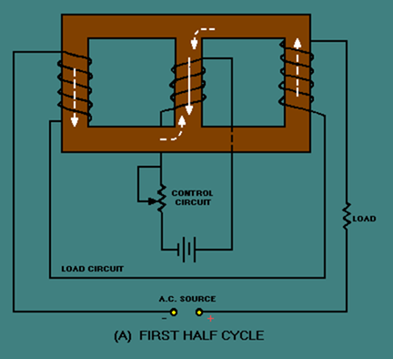
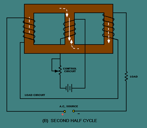
A simple half-wave magnetic amplifier is shown in figure 3-38. This is a half-wave magnetic amplifier because it uses a half-wave rectifier. During the first half cycle of the load voltage, the diode conducts and the load windings develop load flux as shown in view (A) by the dashed-line arrows. The load flux from the two load coils cancels and has no effect on the control flux. During the second half cycle, the diode does not conduct and the load coils develop no flux, as shown in view (B). The load flux never has to reverse direction as it did in the saturable-core reactor, so the hysteresis loss is eliminated.
Figure 3-38A. – Simple half-wave magnetic amplifier. FIRST HALF CYCLE

image

Figure 3-38B. – Simple half-wave magnetic amplifier. SECOND HALF CYCLE

image
The circuit shown in figure 3-38 is only able to use half of the load voltage (and therefore half the possible load power) since the diode blocks current during half the load-voltage cycle. A full-wave rectifier used in place of CR1 would allow current flow during the entire cycle of load voltage while still preventing hysteresis loss.
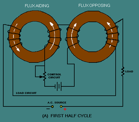
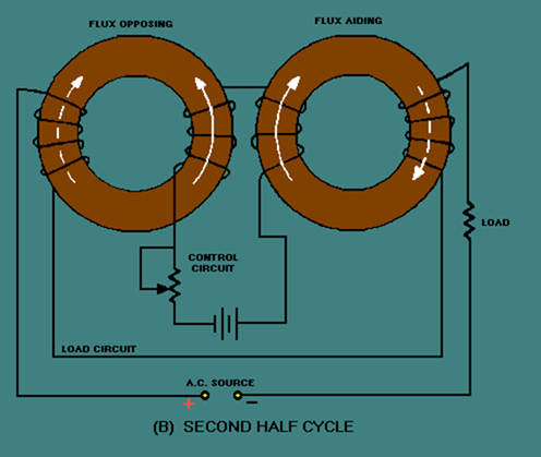
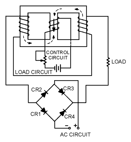
Figure 3-39 shows a simple full-wave magnetic amplifier. The bridge circuit of CR1, CR2, CR3, CR4 allows current to flow in the load circuit during the entire load voltage cycle, but the load current is always in the same direction. This current flow in one direction prevents hysteresis loss.
View (A) shows that during the first half cycle of load voltage, current flows through CR1, the load coils, and CR3. View (B) shows that during the second half cycle, load current flows through CR2, the load coils, and CR4.
Figure 3-39A. – Simple full-wave magnetic amplifier. FIRST HALF CYCLE

image
Figure 3-39B. – Simple full-wave magnetic amplifier. SECOND HALF CYCLE

image
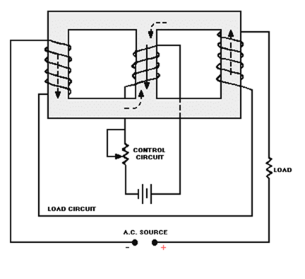
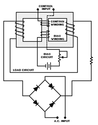
Up to this point, the control circuit of the magnetic amplifier has been shown with d.c. applied to it. Magnetic-amplifier control circuits should accept a.c. input signals as well as d.c. input signals. As shown earlier in figure 3-34, a saturable-core reactor has an ideal operating point. Some d.c. must always be applied to bring the saturable core to that operating point. This d.c. is called BIAS. the most effective way to apply bias to the saturable core and also allow a.c. input signals to control the magnetic amplifier is to use a bias winding. A full-wave magnetic amplifier with a bias winding is shown in figure 3-40.
Figure 3-40. – Full-wave magnetic amplifier with bias winding.

image
In the circuit shown in figure 3-40, the bias circuit is adjusted to set the saturable-core reactor at the ideal operating point. Input signals, represented by the a.c. source symbol, are applied to the control input. The true power of the load circuit is controlled by the control input signal (a.c.)
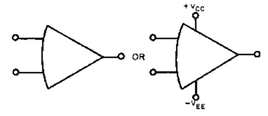
The block diagram symbol for a magnetic amplifier is shown in figure 3-41. The triangle is the general symbol for an amplifier. The saturable-core reactor symbol in the center of the triangle identifies the amplifier as a magnetic amplifier. Notice the input and output signals shown. The input signal is a small-amplitude, low-power a.c. signal. The output signal is a pulsating d.c. with an amplitude that varies. This variation is controlled by the input signal and represents a power gain of 1000.
Figure 3-41. – Magnetic amplifier input and output signals.

image
Some magnetic amplifiers are designed so a.c. goes through the load rather than pulsating d.c. This is done by placing the load in a different circuit position with respect to the rectifier. The principle of the magnetic amplifier remains the same: Control current still controls load current.
Magnetic amplifiers provide a way of accurately controlling large amounts of power. They are used in servosystems (which are covered later in this training series), temperature or pressure indicators, and power supplies.
This chapter has presented only the basic operating theory of saturable-core reactors and magnetic amplifiers. For your convenience, simple schematic diagrams have been used to illustrate this material. When magnetic amplifiers and saturable-core reactors are used in actual equipment, the schematics may be more complex than those you have seen here. Also, you may find coils used in addition to those presented in this chapter. The technical manual for the equipment in question should contain the information you need to supplement what you have read in this chapter.

Q.46 At what portion of the magnetization curve should a magnetic amplifier be operated?

Q.47 How is the effect of load flux on control flux eliminated in a saturable-core reactor?

Q.48 What is the purpose of the rectifier in a magnetic amplifier?

Q.49 What is used to bias a magnetic amplifier so that the control winding remains free to accept control (input) signals?

Q.50 List two common usages of magnetic amplifiers.

Back
Home
Up
Next

SUMMARY OF SPECIAL AMPLIFIERS 

This chapter has presented information on differential amplifiers, operational amplifiers, and magnetic amplifiers. The information that follows summarizes the important points of this chapter.
A DIFFERENCE AMPLIFIER is any amplifier with an output signal dependent upon the difference between the input signals. A two-input, single-output difference amplifier can be made by combining the common-emitter and common-base configurations in a single transistor.

image
A difference amplifier can have input signals that are IN PHASE with each other, 180 DEGREES OUT OF PHASE with each other, or OUT OF PHASE BY SOMETHING OTHER THAN 180 DEGREES with each other.

image

image

image
A DIFFERENTIAL AMPLIFIER has two possible inputs and two possible outputs. The combined output signal is dependent upon the difference between the input signals.

image
A differential amplifier can be configured with a SINGLE INPUT and a SINGLE OUTPUT
image

a SINGLE INPUT and a DIFFERENTIAL OUTPUT

image
or a DIFFERENTIAL INPUT and a DIFFERENTIAL OUTPUT.

imageAn OPERATIONAL AMPLIFIER is an amplifier which has very high gain, very high input impedance, and very low output impedance. An OP AMP is made from three stages: (1) a differential amplifier, (2) a high-gain voltage amplifier, and (3) an output amplifier.

image
Operational amplifiers are usually used in a CLOSED-LOOP OPERATION. This means that degenerative feedback is used to lower the gain and increase the stability of the operational amplifier.
An operational amplifier circuit can be connected with an INVERTING CONFIGURATION

image
or a NONINVERTING CONFIGURATION.

image
The GAIN-BANDWIDTH PRODUCT for an operational amplifier is computed by multiplying the gain by the bandwidth (in hertz). For any given operational amplifier, the gain-bandwidth product will remain the same regardless of the amount of feedback used.

image
A SUMMING AMPLIFIER is an application of an operational amplifier in which the output signal is determined by the sum of the input signals multiplied by the gain of the amplifier:

imageimage
A SCALING AMPLIFIER is a special type of summing amplifier with the output signal determined by multiplying each input signal by a different factor (determined by the ratio of the input-signal resistor and feedback resistor) and then adding these products:

image
image

A DIFFERENCE AMPLIFIER is an application of an operational amplifier in which the output signal is determined by the difference between the input signals multiplied by the gain of the amplifier:

image

image

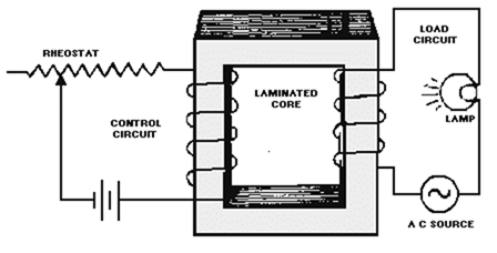
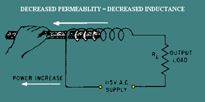
A SATURABLE-CORE REACTOR works upon the principle that increasing the current through a coil decreases the permeability of the core; the decreased permeability decreases the inductance of the coil which causes an increase in current (power) through the load.

image
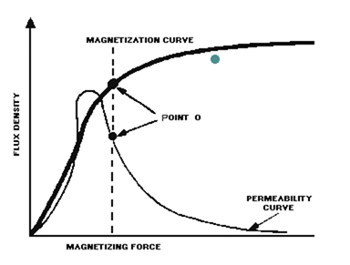
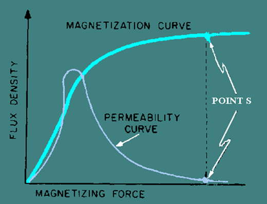
THE IDEAL OPERATING POINT of a saturable-core reactor is on the KNEE OF THE MAGNETIZATION CURVE. At this point, small changes in control current will cause large changes in load current (power).

image
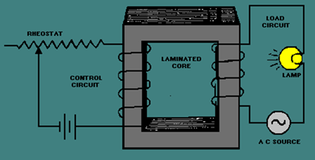
THREE-LEGGED and TOROIDAL saturable-core reactors solve the problem of load flux aiding and opposing control flux during alternate half cycles of the a.c. load current.
image
MAGNETIC AMPLIFIERS use the principle of electromagnetism to amplify signals. They are power amplifiers with a Frequency response normally limited to 100 hertz or below. Magnetic amplifiers use a saturable-core reactor. A magnetic amplifier uses a RECTIFIER to solve the problem of HYSTERESIS LOSS in a saturable-core reactor.

image
A BIAS WINDING allows a d.c. bias voltage to be applied to the saturable-core reactor while a.c. control signals are applied to a separate control winding. In this way a magnetic amplifier can be set to the proper operating point.

image
Back
Home
Up
Next

ANSWERS TO QUESTIONS Q1. THROUGH Q50.

A1. Two inputs, two outputs.

A2. Common emitter (CE) and common base (CB).

A3. No output (the signals will "cancel out").

A4. Equal in shape and frequency to each input signal and larger in amplitude by two times than either input signal.

A5. Equal in shape and frequency to the input signal; larger in amplitude than the input signal; half as large in amplitude as when two input signals were used that were 180 degrees out of phase.
A6. A different shape than the input signals but larger in amplitude.

A7. 100 millivolts.

A8. Each output will be a sine wave with a peak-to-peak amplitude of 100 millivolts. The output signals will be 180 degrees out of phase with each other.

A9. 200 millivolts. A10. 0 volts (the input signals will "cancel out").

A11. Each output signal will be 100 millivolts.

A12.

  • a:  180 degrees out of phase with each other.
  • b:   Output signal number one will be in phase with input signal number two; output signal number two will be in phase with input signal number one.

A13. 200 millivolts.

A14.

  • a.  100 millivolts.
  • b.  No.

A15. Very high gain, very high input impedance, very low output impedance.

A16. An integrated circuit (chip).

A17.image
A18.

  • a. Differential amplifier.
  • b.  Voltage amplifier.
  • c.  Output amplifier.

A19. The use of degenerative (negative) feed-back.

A20. Both the input signal and the feedback signal.
A21. Inverting. Inverting.

A22. 0 volts.

A23. Virtual.

A24. -50 millivolts.

A25. 50 kilohertz (Gain = 10; Gain- Bandwidth Product = 500,000;

image
A26. 60 millivolts.

A27. 1 megahertz.

Open-loop Gain-Bandwidth Product = Closed-loop Gain-Bandwidth Prod.

Open-loop Gain-Bandwidth Product = 200,000 X 30 (Hz)

Open-loop Gain Bandwidth Product = 600,000

Closed-loop Gain Bandwidth Product = 6 X Bandwidth

6,000,000 = 6 X Bandwidth

1,000,000 (Hz) = Bandwidth

A28. The adder simply adds the input signals together while the summing amplifier multiplies the sum of the input signals by the gain of circuit.

A29. Yes, a summing amplifier can have as many inputs as desired.

A30. A summing amplifier that applies a factor to each input signal beforeadding the results.

A31. A scaling amplifier.

A32.

image
A33. 0 volts. (The two inputs to the operational amplifier are both at 0 volts.)

A34. The difference amplifier multiplies the difference between the two inputs by the gain of the circuit while the subtractor merely subtracts one input signal from the other.

A35. No.

A36. A difference amplifier.

A37.

image
A38. 0 volts. (The two inputs to the operational amplifier are both at the same potential.)

A39. An audio (or low) frequency power amplifier.

A40. A change in inductance in a series LR circuit causes a change in true power.

A41. It decreases.

A42. (a) Inductance increases; (b) true power decreases.

A43. Permeability decreases.

A44. A change in inductance.

A45.

image
A46. The knee of the curve.

A47. Use two load windings whose flux effects cancel in the core of the reactor or use two load windings on two toroidal cores so that load flux always aids control flux in one core and opposes control flux in the other core.

A48. The rectifier eliminates hysteresis loss.

A49. A bias winding and associated circuitry.

A50. Servosystems, temperature recorders, or power supplies.

Back
Home
Up


Simplified magnetic amplifier circuitry , summary of special amplifiers and answers to questions q1. Through q50.

SIMPLIFIED MAGNETIC AMPLIFIER CIRCUITRY

If the saturable-core reactor works, why do we need to add a rectifier to produce a magnetic amplifier? To answer this question, recall that in NEETS, module 2 – Introduction to Alternating Current and Transformers, you were told about hysteresis loss. Hysteresis loss occurs because the a.c. applied to a coil causes the tiny molecular magnets (or electron-spin directions) to realign as the polarity of the a.c. changes. This realignment uses up power. The power that is used for realignment is a loss as far as the rest of the circuit is concerned. Because of this hysteresis loss in the saturable-core reactor, the power gain is relatively low. A rectifier added to the load circuit will eliminate the hysteresis loss and increase the gain. This is because the rectifier allows current to flow in only one direction through the load coils.
A simple half-wave magnetic amplifier is shown in figure 3-38. This is a half-wave magnetic amplifier because it uses a half-wave rectifier. During the first half cycle of the load voltage, the diode conducts and the load windings develop load flux as shown in view (A) by the dashed-line arrows. The load flux from the two load coils cancels and has no effect on the control flux. During the second half cycle, the diode does not conduct and the load coils develop no flux, as shown in view (B). The load flux never has to reverse direction as it did in the saturable-core reactor, so the hysteresis loss is eliminated.
Figure 3-38A. – Simple half-wave magnetic amplifier. FIRST HALF CYCLE

image

Figure 3-38B. – Simple half-wave magnetic amplifier. SECOND HALF CYCLE

image
The circuit shown in figure 3-38 is only able to use half of the load voltage (and therefore half the possible load power) since the diode blocks current during half the load-voltage cycle. A full-wave rectifier used in place of CR1 would allow current flow during the entire cycle of load voltage while still preventing hysteresis loss.
Figure 3-39 shows a simple full-wave magnetic amplifier. The bridge circuit of CR1, CR2, CR3, CR4 allows current to flow in the load circuit during the entire load voltage cycle, but the load current is always in the same direction. This current flow in one direction prevents hysteresis loss.
View (A) shows that during the first half cycle of load voltage, current flows through CR1, the load coils, and CR3. View (B) shows that during the second half cycle, load current flows through CR2, the load coils, and CR4.
Figure 3-39A. – Simple full-wave magnetic amplifier. FIRST HALF CYCLE

image
Figure 3-39B. – Simple full-wave magnetic amplifier. SECOND HALF CYCLE

image
Up to this point, the control circuit of the magnetic amplifier has been shown with d.c. applied to it. Magnetic-amplifier control circuits should accept a.c. input signals as well as d.c. input signals. As shown earlier in figure 3-34, a saturable-core reactor has an ideal operating point. Some d.c. must always be applied to bring the saturable core to that operating point. This d.c. is called BIAS. the most effective way to apply bias to the saturable core and also allow a.c. input signals to control the magnetic amplifier is to use a bias winding. A full-wave magnetic amplifier with a bias winding is shown in figure 3-40.
Figure 3-40. – Full-wave magnetic amplifier with bias winding.

image
In the circuit shown in figure 3-40, the bias circuit is adjusted to set the saturable-core reactor at the ideal operating point. Input signals, represented by the a.c. source symbol, are applied to the control input. The true power of the load circuit is controlled by the control input signal (a.c.)
The block diagram symbol for a magnetic amplifier is shown in figure 3-41. The triangle is the general symbol for an amplifier. The saturable-core reactor symbol in the center of the triangle identifies the amplifier as a magnetic amplifier. Notice the input and output signals shown. The input signal is a small-amplitude, low-power a.c. signal. The output signal is a pulsating d.c. with an amplitude that varies. This variation is controlled by the input signal and represents a power gain of 1000.
Figure 3-41. – Magnetic amplifier input and output signals.

image
Some magnetic amplifiers are designed so a.c. goes through the load rather than pulsating d.c. This is done by placing the load in a different circuit position with respect to the rectifier. The principle of the magnetic amplifier remains the same: Control current still controls load current.
Magnetic amplifiers provide a way of accurately controlling large amounts of power. They are used in servosystems (which are covered later in this training series), temperature or pressure indicators, and power supplies.
This chapter has presented only the basic operating theory of saturable-core reactors and magnetic amplifiers. For your convenience, simple schematic diagrams have been used to illustrate this material. When magnetic amplifiers and saturable-core reactors are used in actual equipment, the schematics may be more complex than those you have seen here. Also, you may find coils used in addition to those presented in this chapter. The technical manual for the equipment in question should contain the information you need to supplement what you have read in this chapter.

Q.46 At what portion of the magnetization curve should a magnetic amplifier be operated?

Q.47 How is the effect of load flux on control flux eliminated in a saturable-core reactor?

Q.48 What is the purpose of the rectifier in a magnetic amplifier?

Q.49 What is used to bias a magnetic amplifier so that the control winding remains free to accept control (input) signals?

Q.50 List two common usages of magnetic amplifiers.

Back
Home
Up
Next

SUMMARY OF SPECIAL AMPLIFIERS 

This chapter has presented information on differential amplifiers, operational amplifiers, and magnetic amplifiers. The information that follows summarizes the important points of this chapter.
A DIFFERENCE AMPLIFIER is any amplifier with an output signal dependent upon the difference between the input signals. A two-input, single-output difference amplifier can be made by combining the common-emitter and common-base configurations in a single transistor.

image
A difference amplifier can have input signals that are IN PHASE with each other, 180 DEGREES OUT OF PHASE with each other, or OUT OF PHASE BY SOMETHING OTHER THAN 180 DEGREES with each other.

image

image

image
A DIFFERENTIAL AMPLIFIER has two possible inputs and two possible outputs. The combined output signal is dependent upon the difference between the input signals.

image
A differential amplifier can be configured with a SINGLE INPUT and a SINGLE OUTPUT
image

a SINGLE INPUT and a DIFFERENTIAL OUTPUT

image
or a DIFFERENTIAL INPUT and a DIFFERENTIAL OUTPUT.

imageAn OPERATIONAL AMPLIFIER is an amplifier which has very high gain, very high input impedance, and very low output impedance. An OP AMP is made from three stages: (1) a differential amplifier, (2) a high-gain voltage amplifier, and (3) an output amplifier.

image
Operational amplifiers are usually used in a CLOSED-LOOP OPERATION. This means that degenerative feedback is used to lower the gain and increase the stability of the operational amplifier.
An operational amplifier circuit can be connected with an INVERTING CONFIGURATION

image
or a NONINVERTING CONFIGURATION.

image
The GAIN-BANDWIDTH PRODUCT for an operational amplifier is computed by multiplying the gain by the bandwidth (in hertz). For any given operational amplifier, the gain-bandwidth product will remain the same regardless of the amount of feedback used.

image
A SUMMING AMPLIFIER is an application of an operational amplifier in which the output signal is determined by the sum of the input signals multiplied by the gain of the amplifier:

imageimage
A SCALING AMPLIFIER is a special type of summing amplifier with the output signal determined by multiplying each input signal by a different factor (determined by the ratio of the input-signal resistor and feedback resistor) and then adding these products:

image
image

A DIFFERENCE AMPLIFIER is an application of an operational amplifier in which the output signal is determined by the difference between the input signals multiplied by the gain of the amplifier:

image

image

A SATURABLE-CORE REACTOR works upon the principle that increasing the current through a coil decreases the permeability of the core; the decreased permeability decreases the inductance of the coil which causes an increase in current (power) through the load.

image
THE IDEAL OPERATING POINT of a saturable-core reactor is on the KNEE OF THE MAGNETIZATION CURVE. At this point, small changes in control current will cause large changes in load current (power).

image
THREE-LEGGED and TOROIDAL saturable-core reactors solve the problem of load flux aiding and opposing control flux during alternate half cycles of the a.c. load current.
image
MAGNETIC AMPLIFIERS use the principle of electromagnetism to amplify signals. They are power amplifiers with a Frequency response normally limited to 100 hertz or below. Magnetic amplifiers use a saturable-core reactor. A magnetic amplifier uses a RECTIFIER to solve the problem of HYSTERESIS LOSS in a saturable-core reactor.

image
A BIAS WINDING allows a d.c. bias voltage to be applied to the saturable-core reactor while a.c. control signals are applied to a separate control winding. In this way a magnetic amplifier can be set to the proper operating point.

image
Back
Home
Up
Next

ANSWERS TO QUESTIONS Q1. THROUGH Q50.

A1. Two inputs, two outputs.

A2. Common emitter (CE) and common base (CB).

A3. No output (the signals will "cancel out").

A4. Equal in shape and frequency to each input signal and larger in amplitude by two times than either input signal.

A5. Equal in shape and frequency to the input signal; larger in amplitude than the input signal; half as large in amplitude as when two input signals were used that were 180 degrees out of phase.
A6. A different shape than the input signals but larger in amplitude.

A7. 100 millivolts.

A8. Each output will be a sine wave with a peak-to-peak amplitude of 100 millivolts. The output signals will be 180 degrees out of phase with each other.

A9. 200 millivolts. A10. 0 volts (the input signals will "cancel out").

A11. Each output signal will be 100 millivolts.

A12.

  • a:  180 degrees out of phase with each other.
  • b:   Output signal number one will be in phase with input signal number two; output signal number two will be in phase with input signal number one.

A13. 200 millivolts.

A14.

  • a.  100 millivolts.
  • b.  No.

A15. Very high gain, very high input impedance, very low output impedance.

A16. An integrated circuit (chip).

A17.image
A18.

  • a. Differential amplifier.
  • b.  Voltage amplifier.
  • c.  Output amplifier.

A19. The use of degenerative (negative) feed-back.

A20. Both the input signal and the feedback signal.
A21. Inverting. Inverting.

A22. 0 volts.

A23. Virtual.

A24. -50 millivolts.

A25. 50 kilohertz (Gain = 10; Gain- Bandwidth Product = 500,000;

image
A26. 60 millivolts.

A27. 1 megahertz.

Open-loop Gain-Bandwidth Product = Closed-loop Gain-Bandwidth Prod.

Open-loop Gain-Bandwidth Product = 200,000 X 30 (Hz)

Open-loop Gain Bandwidth Product = 600,000

Closed-loop Gain Bandwidth Product = 6 X Bandwidth

6,000,000 = 6 X Bandwidth

1,000,000 (Hz) = Bandwidth

A28. The adder simply adds the input signals together while the summing amplifier multiplies the sum of the input signals by the gain of circuit.

A29. Yes, a summing amplifier can have as many inputs as desired.

A30. A summing amplifier that applies a factor to each input signal beforeadding the results.

A31. A scaling amplifier.

A32.

image
A33. 0 volts. (The two inputs to the operational amplifier are both at 0 volts.)

A34. The difference amplifier multiplies the difference between the two inputs by the gain of the circuit while the subtractor merely subtracts one input signal from the other.

A35. No.

A36. A difference amplifier.

A37.

image
A38. 0 volts. (The two inputs to the operational amplifier are both at the same potential.)

A39. An audio (or low) frequency power amplifier.

A40. A change in inductance in a series LR circuit causes a change in true power.

A41. It decreases.

A42. (a) Inductance increases; (b) true power decreases.

A43. Permeability decreases.

A44. A change in inductance.

A45.

image
A46. The knee of the curve.

A47. Use two load windings whose flux effects cancel in the core of the reactor or use two load windings on two toroidal cores so that load flux always aids control flux in one core and opposes control flux in the other core.

A48. The rectifier eliminates hysteresis loss.

A49. A bias winding and associated circuitry.

A50. Servosystems, temperature recorders, or power supplies.

Back
Home
Up


Simplified magnetic amplifier circuitry , summary of special amplifiers and answers to questions q1. Through q50.

SIMPLIFIED MAGNETIC AMPLIFIER CIRCUITRY

If the saturable-core reactor works, why do we need to add a rectifier to produce a magnetic amplifier? To answer this question, recall that in NEETS, module 2 – Introduction to Alternating Current and Transformers, you were told about hysteresis loss. Hysteresis loss occurs because the a.c. applied to a coil causes the tiny molecular magnets (or electron-spin directions) to realign as the polarity of the a.c. changes. This realignment uses up power. The power that is used for realignment is a loss as far as the rest of the circuit is concerned. Because of this hysteresis loss in the saturable-core reactor, the power gain is relatively low. A rectifier added to the load circuit will eliminate the hysteresis loss and increase the gain. This is because the rectifier allows current to flow in only one direction through the load coils.
A simple half-wave magnetic amplifier is shown in figure 3-38. This is a half-wave magnetic amplifier because it uses a half-wave rectifier. During the first half cycle of the load voltage, the diode conducts and the load windings develop load flux as shown in view (A) by the dashed-line arrows. The load flux from the two load coils cancels and has no effect on the control flux. During the second half cycle, the diode does not conduct and the load coils develop no flux, as shown in view (B). The load flux never has to reverse direction as it did in the saturable-core reactor, so the hysteresis loss is eliminated.
Figure 3-38A. – Simple half-wave magnetic amplifier. FIRST HALF CYCLE

image

Figure 3-38B. – Simple half-wave magnetic amplifier. SECOND HALF CYCLE

image
The circuit shown in figure 3-38 is only able to use half of the load voltage (and therefore half the possible load power) since the diode blocks current during half the load-voltage cycle. A full-wave rectifier used in place of CR1 would allow current flow during the entire cycle of load voltage while still preventing hysteresis loss.
Figure 3-39 shows a simple full-wave magnetic amplifier. The bridge circuit of CR1, CR2, CR3, CR4 allows current to flow in the load circuit during the entire load voltage cycle, but the load current is always in the same direction. This current flow in one direction prevents hysteresis loss.
View (A) shows that during the first half cycle of load voltage, current flows through CR1, the load coils, and CR3. View (B) shows that during the second half cycle, load current flows through CR2, the load coils, and CR4.
Figure 3-39A. – Simple full-wave magnetic amplifier. FIRST HALF CYCLE

image
Figure 3-39B. – Simple full-wave magnetic amplifier. SECOND HALF CYCLE

image
Up to this point, the control circuit of the magnetic amplifier has been shown with d.c. applied to it. Magnetic-amplifier control circuits should accept a.c. input signals as well as d.c. input signals. As shown earlier in figure 3-34, a saturable-core reactor has an ideal operating point. Some d.c. must always be applied to bring the saturable core to that operating point. This d.c. is called BIAS. the most effective way to apply bias to the saturable core and also allow a.c. input signals to control the magnetic amplifier is to use a bias winding. A full-wave magnetic amplifier with a bias winding is shown in figure 3-40.
Figure 3-40. – Full-wave magnetic amplifier with bias winding.

image
In the circuit shown in figure 3-40, the bias circuit is adjusted to set the saturable-core reactor at the ideal operating point. Input signals, represented by the a.c. source symbol, are applied to the control input. The true power of the load circuit is controlled by the control input signal (a.c.)
The block diagram symbol for a magnetic amplifier is shown in figure 3-41. The triangle is the general symbol for an amplifier. The saturable-core reactor symbol in the center of the triangle identifies the amplifier as a magnetic amplifier. Notice the input and output signals shown. The input signal is a small-amplitude, low-power a.c. signal. The output signal is a pulsating d.c. with an amplitude that varies. This variation is controlled by the input signal and represents a power gain of 1000.
Figure 3-41. – Magnetic amplifier input and output signals.

image
Some magnetic amplifiers are designed so a.c. goes through the load rather than pulsating d.c. This is done by placing the load in a different circuit position with respect to the rectifier. The principle of the magnetic amplifier remains the same: Control current still controls load current.
Magnetic amplifiers provide a way of accurately controlling large amounts of power. They are used in servosystems (which are covered later in this training series), temperature or pressure indicators, and power supplies.
This chapter has presented only the basic operating theory of saturable-core reactors and magnetic amplifiers. For your convenience, simple schematic diagrams have been used to illustrate this material. When magnetic amplifiers and saturable-core reactors are used in actual equipment, the schematics may be more complex than those you have seen here. Also, you may find coils used in addition to those presented in this chapter. The technical manual for the equipment in question should contain the information you need to supplement what you have read in this chapter.

Q.46 At what portion of the magnetization curve should a magnetic amplifier be operated?

Q.47 How is the effect of load flux on control flux eliminated in a saturable-core reactor?

Q.48 What is the purpose of the rectifier in a magnetic amplifier?

Q.49 What is used to bias a magnetic amplifier so that the control winding remains free to accept control (input) signals?

Q.50 List two common usages of magnetic amplifiers.

Back
Home
Up
Next

SUMMARY OF SPECIAL AMPLIFIERS 

This chapter has presented information on differential amplifiers, operational amplifiers, and magnetic amplifiers. The information that follows summarizes the important points of this chapter.
A DIFFERENCE AMPLIFIER is any amplifier with an output signal dependent upon the difference between the input signals. A two-input, single-output difference amplifier can be made by combining the common-emitter and common-base configurations in a single transistor.

image
A difference amplifier can have input signals that are IN PHASE with each other, 180 DEGREES OUT OF PHASE with each other, or OUT OF PHASE BY SOMETHING OTHER THAN 180 DEGREES with each other.

image

image

image
A DIFFERENTIAL AMPLIFIER has two possible inputs and two possible outputs. The combined output signal is dependent upon the difference between the input signals.

image
A differential amplifier can be configured with a SINGLE INPUT and a SINGLE OUTPUT
image

a SINGLE INPUT and a DIFFERENTIAL OUTPUT

image
or a DIFFERENTIAL INPUT and a DIFFERENTIAL OUTPUT.

imageAn OPERATIONAL AMPLIFIER is an amplifier which has very high gain, very high input impedance, and very low output impedance. An OP AMP is made from three stages: (1) a differential amplifier, (2) a high-gain voltage amplifier, and (3) an output amplifier.

image
Operational amplifiers are usually used in a CLOSED-LOOP OPERATION. This means that degenerative feedback is used to lower the gain and increase the stability of the operational amplifier.
An operational amplifier circuit can be connected with an INVERTING CONFIGURATION

image
or a NONINVERTING CONFIGURATION.

image
The GAIN-BANDWIDTH PRODUCT for an operational amplifier is computed by multiplying the gain by the bandwidth (in hertz). For any given operational amplifier, the gain-bandwidth product will remain the same regardless of the amount of feedback used.

image
A SUMMING AMPLIFIER is an application of an operational amplifier in which the output signal is determined by the sum of the input signals multiplied by the gain of the amplifier:

imageimage
A SCALING AMPLIFIER is a special type of summing amplifier with the output signal determined by multiplying each input signal by a different factor (determined by the ratio of the input-signal resistor and feedback resistor) and then adding these products:

image
image

A DIFFERENCE AMPLIFIER is an application of an operational amplifier in which the output signal is determined by the difference between the input signals multiplied by the gain of the amplifier:

image

image

A SATURABLE-CORE REACTOR works upon the principle that increasing the current through a coil decreases the permeability of the core; the decreased permeability decreases the inductance of the coil which causes an increase in current (power) through the load.

image
THE IDEAL OPERATING POINT of a saturable-core reactor is on the KNEE OF THE MAGNETIZATION CURVE. At this point, small changes in control current will cause large changes in load current (power).

image
THREE-LEGGED and TOROIDAL saturable-core reactors solve the problem of load flux aiding and opposing control flux during alternate half cycles of the a.c. load current.
image
MAGNETIC AMPLIFIERS use the principle of electromagnetism to amplify signals. They are power amplifiers with a Frequency response normally limited to 100 hertz or below. Magnetic amplifiers use a saturable-core reactor. A magnetic amplifier uses a RECTIFIER to solve the problem of HYSTERESIS LOSS in a saturable-core reactor.

image
A BIAS WINDING allows a d.c. bias voltage to be applied to the saturable-core reactor while a.c. control signals are applied to a separate control winding. In this way a magnetic amplifier can be set to the proper operating point.

image
Back
Home
Up
Next

ANSWERS TO QUESTIONS Q1. THROUGH Q50.

A1. Two inputs, two outputs.

A2. Common emitter (CE) and common base (CB).

A3. No output (the signals will "cancel out").

A4. Equal in shape and frequency to each input signal and larger in amplitude by two times than either input signal.

A5. Equal in shape and frequency to the input signal; larger in amplitude than the input signal; half as large in amplitude as when two input signals were used that were 180 degrees out of phase.
A6. A different shape than the input signals but larger in amplitude.
A7. 100 millivolts.
A8. Each output will be a sine wave with a peak-to-peak amplitude of 100 millivolts. The output signals will be 180 degrees out of phase with each other.

A9. 200 millivolts. A10. 0 volts (the input signals will "cancel out").

A11. Each output signal will be 100 millivolts.

A12.

  • a:  180 degrees out of phase with each other.
  • b:   Output signal number one will be in phase with input signal number two; output signal number two will be in phase with input signal number one.

A13. 200 millivolts.

A14.

  • a.  100 millivolts.
  • b.  No.

A15. Very high gain, very high input impedance, very low output impedance.

A16. An integrated circuit (chip).

A17.image
A18.

  • a. Differential amplifier.
  • b.  Voltage amplifier.
  • c.  Output amplifier.

A19. The use of degenerative (negative) feed-back.

A20. Both the input signal and the feedback signal.
A21. Inverting. Inverting.

A22. 0 volts.

A23. Virtual.

A24. -50 millivolts.

A25. 50 kilohertz (Gain = 10; Gain- Bandwidth Product = 500,000;

image
A26. 60 millivolts.

A27. 1 megahertz.

Open-loop Gain-Bandwidth Product = Closed-loop Gain-Bandwidth Prod.

Open-loop Gain-Bandwidth Product = 200,000 X 30 (Hz)

Open-loop Gain Bandwidth Product = 600,000

Closed-loop Gain Bandwidth Product = 6 X Bandwidth

6,000,000 = 6 X Bandwidth

1,000,000 (Hz) = Bandwidth

A28. The adder simply adds the input signals together while the summing amplifier multiplies the sum of the input signals by the gain of circuit.

A29. Yes, a summing amplifier can have as many inputs as desired.

A30. A summing amplifier that applies a factor to each input signal beforeadding the results.

A31. A scaling amplifier.

A32.

image
A33. 0 volts. (The two inputs to the operational amplifier are both at 0 volts.)

A34. The difference amplifier multiplies the difference between the two inputs by the gain of the circuit while the subtractor merely subtracts one input signal from the other.

A35. No.

A36. A difference amplifier.

A37.

image
A38. 0 volts. (The two inputs to the operational amplifier are both at the same potential.)

A39. An audio (or low) frequency power amplifier.

A40. A change in inductance in a series LR circuit causes a change in true power.

A41. It decreases.

A42. (a) Inductance increases; (b) true power decreases.

A43. Permeability decreases.

A44. A change in inductance.

A45.

image
A46. The knee of the curve.

A47. Use two load windings whose flux effects cancel in the core of the reactor or use two load windings on two toroidal cores so that load flux always aids control flux in one core and opposes control flux in the other core.

A48. The rectifier eliminates hysteresis loss.

A49. A bias winding and associated circuitry.

A50. Servosystems, temperature recorders, or power supplies.

Back
Home
Up


Scaling amplifier , difference amplifier , circuit for q31 through q33 , circuit for q36 through q38 , magnetic amplifiers , methods of changing inductance , flux paths in a saturable-core reactor and flux aiding

Scaling amplifier

One final type of summing amplifier is the SCALING AMPLIFIER. This circuit multiplies each input by a factor (the factor is determined by circuit design) and then adds these values together. The factor that is used to multiply each input is determined by the ratio of the feedback resistor to the input resistor. For example, you could design a circuit that would produce the following output from three inputs (E1, E2, E3):

image
Using input resistors R1 for input number one (E1), R2 for input number two (E2), R3 for input number three (E3), and R4 for the feedback resistor, you could calculate the values for the resistors:

image
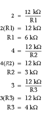
Any resistors that will provide the ratios shown above could be used. If the feedback resistor (R4) is a 12-kilohm resistor, the values of the other resistors would be:image

Figure 3-24 is the schematic diagram of a scaling amplifier with the values calculated above.
Figure 3-24. – Scaling amplifier.

image
To see if the circuit will produce the desired output, calculate the currents and voltages as done for the previous circuits.
With:

imagethe output should be:

image
Calculate the current for each input:

image
Calculate the output voltage:image
You have now seen how an operational amplifier can be used in a circuit as an adder, a summing amplifier, and a scaling amplifier.
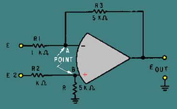
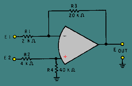
Difference Amplifier (Subtractor) A difference amplifier will produce an output based on the difference between the input signals. The subtractor circuit shown in figure 3-25 will produce the following output:

image
Figure 3-25. – Subtractor circuit.

image
Normally, difference amplifier circuits have the ratio of the inverting input resistor to the feedback resistor equal to the ratio of the noninverting input resistors. In other words, for figure 3-25:image
and, by inverting both sides:

image

Back
Home
Up
Next

Difference amplifier

For ease of explanation, in the circuit shown in figure 3-25 all the resistors have a value of 1 kilohm, but any value could be used as long as the above ratio is true. For a subtractor circuit, the values of R1 and R3 must also be equal, and therefore, the values of R2 and R4 must be equal. It is NOT necessary that the value of R1 equal the value of R2.
Using figure 3-25, assume that the input signals are:

image
The output signal should be:

image
To check this output, first compute the value of R2 plus R4:image
With this value, compute the current through R2 (IR2):
image(indicating current flow from left to right)
Next, compute the voltage drop across R2 (ER2):

image
Then compute the voltage at point B:

image
Since point B and point A will be at the same potential in an operational amplifier:image
Now compute the voltage developed by R1 (ER1):
Compute the current through R1 (IR1):image
Compute the voltage developed by R3 (ER3):image
Add this to the voltage at point A to compute the output voltage (E out):

image
As you can see, the circuit shown in figure 3-25 functions as a subtractor. But just as an adder is only one kind of summing amplifier, a subtractor is only one kind of difference amplifier. A difference amplifier can amplify the difference between two signals. For example, with two inputs (E1 and E2) and a gain of five, a difference amplifier will produce an output signal which is:image
The difference amplifier that will produce that output is shown in figure 3-26. Notice that this circuit is the same as the subtractor shown in figure 3-25 except for the values of R3 and R4. The gain of this difference amplifier is:
Figure 3-26. – Difference amplifier.image

image

Then, for a difference amplifier:image
With the same inputs that were used for the subtractor, (E1 = + 3 V; E2 = + 12 V) the output of the difference amplifier should be five times the output of the subtractor (Eout = + 45 V).
Following the same steps used for the subtractor:
First compute the value of R2 plus R4:image
With this value, compute the current through R2 (IR2):

image
Next, compute the voltage drop across R2 (ER2):

image
Then, compute the voltage at point B:

image
Since point A and point B will be at the same potential in an operational amplifier:

image
Now compute the voltage developed by R1 (ER1):image
Compute the current through R1 (IR1):

image

Compute the voltage developed by R3 (ER3):

image

Add this voltage to the voltage at point A to compute the output voltage (Eout):

image
This was the output desired, so the circuit works as a difference amplifier.

Q.28 What is the difference between a summing amplifier and an adder circuit?

Q.29 Can a summing amplifier have more than two inputs?

Q.30 What is a scaling amplifier?

Back
Home
Up
Next

Circuit for Q31 through Q33

Refer to figure 3-27 in answering Q31 through Q33.
Figure 3-27. – Circuit for Q31 through Q33.

image
Q.31 What type of circuit is figure 3-27?

Q.32 If: E1 = +2VAnd: E2 = +6VThen Eout = ?

Q.33 What is the difference in potential between the inverting (-) and noninverting (+) inputs to the operational amplifier when:E1 = +6VandE2 = +2V

Q.34 What is the difference between a subtractor and a difference amplifier?

Q.35 Can a difference amplifier have more than two inputs?

Back
Home
Up
Next

Circuit for Q36 through Q38

Refer to figure 3-28 in answering Q36 through Q38.
Figure 3-28. – Circuit for Q36 through Q38.

image
Q.36 What type of circuit is figure 3-28?

Q.37 If: E1 = +5VAnd: E2 = +11VThen Eout = ?

Q.38 What is the difference in potential between the inverting (-) and noninverting (+) inputs to the operational amplifier when:E1 = +2VandE2 = +4V

Back
Home
Up
Next

MAGNETIC AMPLIFIERS

You have now been shown various ways that electron tubes (NEETS, module 6) and transistors (NEETS, module 7) can be used to amplify signals. You have also been shown the way in which this is done. There is another type of amplifier in use – the MAGNETIC AMPLIFIER, sometimes called the MAG AMP.
The magnetic amplifier has certain advantages over other types of amplifiers. These include (1) high efficiency (up to 90 percent); (2) reliability (long life, freedom from maintenance, reduction of spare parts inventory); (3) ruggedness (shock and vibration resistance, high overload capability, freedom from effects of moisture); and (4) no warm-up time. The magnetic amplifier has no moving parts and can be hermetically sealed within a case similar to the conventional dry-type transformer.
However, the magnetic amplifier has a few disadvantages. For example, it cannot handle low-level signals; it is not useful at high frequencies; it has a time delay associated with the magnetic effects; and the output waveform is not an exact reproduction of the input waveform (poor fidelity).
The magnetic amplifier is important, however, to many phases of naval engineering because it provides a rugged, trouble-free device that has many applications aboard ship and in aircraft. These applications include throttle controls on the main engines of ships; speed, frequency, voltage, current, and temperature controls on auxiliary equipment; and fire control, servomechanisms, and stabilizers for guns, radar, and sonar equipment.
As stated earlier, the magnetic amplifier does not amplify magnetism, but uses electromagnetism to amplify a signal. It is a power amplifier with a very limited Frequency response. Technically, it falls into the classification of an audio amplifier; but, since the Frequency response is normally limited to 100 hertz and below, the magnetic amplifier is more correctly called a low-frequency amplifier.
The basic principle of a magnetic amplifier is very simple. (Remember, all amplifiers are current-control devices.) A magnetic amplifier uses a changing inductance to control the power delivered to a load.
BASIC OPERATION OF A MAGNETIC AMPLIFIER
Figure 3-29 shows a simple circuit with a variable inductor in series with a resistor (representing a load). The voltage source is 100 volts at 60 hertz.
Figure 3-29. – Variable inductor in series with a load.

image
What happens when the inductance decreases? The end result is that the power in the load (true power) increases. Why? Look at the following formulas and see how each is affected by a decrease in inductance.

image
(True power is covered in NEETS, Module 2 – Introduction to Alternating Current and Transformers.)
As inductance (L) decreases, XL decreases. As XL decreases, Z decreases. As Z decreases, I increases. Finally, as I increases, true power increases.
This general conclusion can be confirmed by using some actual values of inductance in the formulas along with other values from figure 3-29.
If the value of inductance is 23 millihenries, the formulas yield the following values:

image

Now, if the value of inductance is decreased to 11.7 millihenries, the formulas yield the following values:


image

So a decrease in inductance of 11.3 millihenries (23 mH – 11.7 mH) causes an increase in power to the load (true power) of 625 watts (1125 W – 500 W). If it took 1 watt of power to change the inductance by 11.3 millihenries (by some electrical or mechanical means), figure 3-29 would represent a power amplifier with a gain of 625.

Q.39 What is the frequency classification of a magnetic amplifier?

Q.40 What is the basic principle of a magnetic amplifier?

Q.41 If inductance increases in a series LR circuit, what happens to true power?

Back
Home
Up
Next

METHODS OF CHANGING INDUCTANCE

Since changing the inductance of a coil enables the control of power to a load, what methods are available to change the inductance? Before answering that question, you should recall a few things about magnetism and inductors from NEETS, module 1 – Introduction to Matter, Energy, and Direct Current, chapter 1 – Matter, Energy, and Electricity; and module 2 – Introduction to Alternating Current and Transformers, chapter 2 – Inductance.
Permeability was defined as the measure of the ability of a material to act as a path for additional magnetic lines of force. Soft iron was presented as having high permeability compared with air. In fact, the permeability of unmagnetized iron is 5000 while air has a permeability of 1. A nonmagnetized piece of iron has high permeability because the tiny molecular magnets (Weber’s Theory) or the directions of electron spin (Domain Theory) are able to be aligned by a magnetic field. As they align, they act as a path for the magnetic lines of force.
Earlier NEETS modules state that the inductance of a coil increases directly as the permeability of the core material increases. If a coil is wound around an iron core, the permeability of the core is 5000. Now, if the iron is pulled part way out of the coil of wire, the core is part iron and part air. The permeability of the core decreases. As the permeability of the core decreases, the inductance of the coil decreases. This increases the power delivered to the load (true power). This relationship is shown in figure 3-30.
The system shown in figure 3-30 is not too practical. Even if a motor were used in place of the hand that is shown, the resulting amplifier would be large, expensive, and not easily controlled. If the permeability of a core could be changed by electrical means rather than mechanical, a more practical system would result.
Figure 3-30. – Varying coil inductance with a movable coil.

image
High permeability depends on there being many molecular magnets (or electron spin directions) that can be aligned to provide a path for magnetic lines of force. If almost all of these available paths are already being used, the material is magnetized and there are no more paths for additional lines of force. The "flux density" (number of lines of force passing through a given area) is as high as it can be. This means that the permeability of the material has decreased. When this condition is reached, the core is said to be SATURATED because it is saturated (filled) with all the magnetic lines of force it can pass. At this point, the core has almost the same value of permeability as air (1) instead of the much higher value of permeability (5000) that it had when it was unmagnetized.
Of course, the permeability does not suddenly change from 5000 to 1. The permeability changes as the magnetizing force changes until saturation is reached. At saturation, permeability remains very low no matter how much the magnetizing force increases. If you were to draw a graph of the flux density compared to the magnetizing force, you would have something similar to the graph shown in figure 3-31. Figure 3-31 also includes a curve representing the value of permeability as the magnetizing force increases. Point "s" in figure 3-31 is the point of saturation. The flux density does not increase above point "s," and the permeability is at a steady, low value.
Figure 3-31. – Magnetization and permeability curves.image
You have now seen how a change in the magnetizing force causes a change in permeability. The next question is, how do you change the magnetizing force? Magnetizing force is a function of AMPERE-TURNS. (An ampere-turn is the magnetomotive force developed by 1 ampere of current flowing in a coil of one turn.) If you increase the ampere-turns of a coil, the magnetizing force increases. Since it is not practical to increase the number of turns, the easiest way to accomplish this is to increase the current through the coil.
If you increase the current through a coil, you increase the ampere-turns. By increasing the ampere-turns you increase the magnetizing force. At some point, this causes a decrease in the permeability of the core. With the permeability of the core decreased, the inductance of the coil decreases. As said before, a decrease in the inductance causes an increase in power through the load. A device that uses this arrangement is called a SATURABLE-CORE REACTOR or SATURABLE REACTOR.
SATURABLE-CORE REACTOR
A saturable-core reactor is a magnetic-core reactor (coil) whose reactance is controlled by changing the permeability of the core. The permeability of the core is changed by varying a unidirectional flux (flux in one direction) through the core.
Figure 3-32 shows a saturable-core reactor that is used to control the intensity of a lamp. Notice that two coils are wound around a single core. The coil on the left is connected to a rheostat and a battery. This coil is called the control coil because it is part of the control circuit. The coil on the right is connected to a lamp (the load) and an a.c. source. This coil is called the load coil because it is part of the load circuit.
As the wiper (the movable connection) of the rheostat is moved toward the right, there is less resistance in the control circuit. With less resistance, the control-circuit current increases. This causes the amount of magnetism in the core to increase and the inductance of the coil in the load circuit to decrease (because the core is common to both coils). With less inductance in the load circuit, load current increases and the lamp gets brighter.
Figure 3-32. – A simple saturable-core reactor circuit.

image
The schematic diagram of this circuit is shown in figure 3-33. L1 is the schematic symbol for a saturable-core reactor. The control winding is shown with five loops, and the load winding is shown with three loops. The double bar between the inductors stands for an iron core, and the symbol that cuts across the two windings is a saturable-core symbol indicating that the two windings share a saturable core.
Figure 3-33. – Schematic diagram of a simple saturable-core reactor.image
Now that you have seen the basic operation of a saturable-core reactor, there is one other idea to discuss before moving on to the circuitry of a magnetic amplifier. There is a point upon the magnetization curve where the saturable-core reactor should be operated. The ideal operating point is the place in which a small increase in control current will cause a large increase in output power and a small decrease in control current will cause a large decrease in output power. This point is on the flattest portion of the permeability curve (after its peak).
Figure 3-34 shows the magnetization and permeability curves for a saturable-core reactor with the ideal operating point (point "O") indicated. Notice point "O" on the magnetization curve. The portion of the magnetization curve where point "O" is located is called the KNEE OF THE CURVE. The knee of the curve is the point of maximum curvature. It is called the "knee" because it looks like the knee of a leg that is bent. Saturable-core reactors and magnetic amplifiers should be operated on the knee of the magnetization curve.
Figure 3-34. – Magnetization and permeability curves with operating point.

image

Back
Home
Up
Next


Flux paths in a saturable-core reactor. FLUX AIDING

When the saturable-core reactor is set at the knee of the magnetization curve, any small increase in control current will cause a large increase in load current. Any small decrease in control current will cause a large decrease in load current. That is why point "O" is the ideal operating point-because small changes in control current will cause large changes in load current. In other words, the saturable-core reactor can amplify the control current. However, a saturable-core reactor is NOT a magnetic amplifier. You will find out a little later how a magnetic amplifier differs from a saturable-core reactor. First you should know a few more things about the saturable-core reactor.
If a d.c. voltage is applied to the control winding of a saturable-core reactor and an a.c. voltage is applied to the load windings, the a.c. flux will aid the d.c. flux on one half cycle and oppose the d.c. flux on the other half cycle. This is shown in figure 3-35. Load flux is indicated by the dashed-line arrows, and control flux is indicated by the solid-line arrows. View (A) shows the load and control flux adding during one half cycle of the a.c. View (B) of the figure shows the load and control flux opposing during the other half cycle of the a.c.
Figure 3-35A. – Flux paths in a saturable-core reactor. FLUX AIDING

image
Figure 3-35B. – Flux paths in a saturable-core reactor. FLUX OPPOSING

image
This situation causes the operating point of the saturable-core reactor to shift with the applied a.c. However, the situation would be better if the load flux was not an influence on the control flux. Figure 3-36 shows a circuit in which this is accomplished.
During the first half cycle, the load circuit flux (dashed-line arrows) cancels in the center leg of the core. This is shown in figure 3-36, view (A). As a result, there is no effect upon the flux from the control circuit. During the second half cycle, the polarity of the a.c. (and therefore the polarity of the flux) reverses as shown in view (B). The result is the same as it was during the first half cycle. There is no effect upon the control circuit flux.
Figure 3-36A. – Three-legged, saturable-core reactor. FIRST HALF CYCLE

image
Figure 3-36B. – Three-legged, saturable-core reactor. SECOND HALF CYCLE

image
Another approach to solving the problem of load flux affecting control flux is shown in figure 3-37. Figure 3-37 shows a toroidal saturable-core reactor. The shape of these cores is a toroid (donut shape). The windings are wound around the cores so that the load flux aids the control flux in one core and opposes the control flux in the other core.
During the first half cycle, the flux aids in the left core and opposes in the right core, as shown in figure 3-37, view (A). During the second half cycle, the flux opposes in the left core and aids in the right core, as shown in view (B). Regardless of the amount of load flux or polarity of the load voltage, there is no net effect of load flux on control flux.
Figure 3-37A. – Toroidal saturable-core reactor. FIRST HALF CYCLE

image
Figure 3-37B. – Toroidal saturable-core reactor. SECOND HALF CYCLE

image
Figures 3-36 and 3-37 both represent practical, workable saturable-core reactors. Circuits similar to these are actually used to control lighting in auditoriums or electric industrial furnaces. These circuits are sometimes referred to as magnetic amplifiers, but that is NOT technically correct. A magnetic amplifier differs from a saturable-core reactor in one important aspect: A magnetic amplifier has a rectifier in addition to a saturable-core reactor.

Q.42 If the permeability of the core of a coil increases, what happens to (a) inductance and (b) true power in the circuit?

Q.43 What happens to the permeability of an iron core as the current increases from the operating point to a large value?

Q.44 If two coils are wound on a single iron core, what will a change in current in one coil cause in the other coil?

Q.45 What symbol in figure 3-33 indicates a saturable core connecting two windings?

Back
Home
Up
Next


Current flow in the operational circuit , bandwidth limitations and applications of operational amplifiers

Current flow in the operational circuit

You can compute the values for view (C) and prove that point A in that circuit is also at virtual ground.
The whole point is that the inverting input to the operational amplifier shown in figure 3-13 is at virtual ground since it is at 0 volts (for all practical purposes). Because the inverting input is at 0 volts, there will be no current (for all practical purposes) flowing into the operational amplifier from the connection point of R1 and R2.
Given these conditions, the characteristics of this circuit are determined almost entirely by the values of R1 and R2. Figure 3-15 should help show how the values of R1 and R2 determine the circuit characteristics.
Figure 3-15. – Current flow in the operational circuit.

image
NOTE: It should be stressed at this point that for purpose of explanation the operational amplifier is a theoretically perfect amplifier. In actual practice we are dealing with less than perfect. In the practical operational amplifier there will be a slight input current with a resultant power loss. This small signal can be measured at the theoretical point of virtual ground. This does not indicate faulty operation.
The input signal causes current to flow through R1. (Only the positive half cycle of the input signal is shown and will be discussed.) Since the voltage at the inverting input of the operational amplifier is at 0 volts, the input current (Iin) is computed by:imageThe output signal (which is opposite in phase to the input signal) causes a feedback current (Ifdbk) to flow through R2. The left-hand side of R2 is at 0 volts (point A) and the right-hand side is at Eout. Therefore, the feedback current is computed by:

image
(The minus sign indicates that Eout is 180 degrees out of phase with Ein and should not be confused with output polarity.)
Since no current flows into or out of the inverting input of the operational amplifier, any current reaching point A from R1 must flow out of point A through R2. Therefore, the input current (Iin) and the feedback current (Ifdbk) must be equal. Now we can develop a mathematical relationship between the input and output signals and R1 and R2.
Mathematically:image
If you multiply both sides of the equation by R1:
If you divide both sides of the equation by Eout:

image
By inverting both sides of the equation:image

You should recall that the voltage gain of a stage is defined as the output voltage divided by the input voltage:image
Therefore, the voltage gain of the inverting configuration of the operational amplifier is expressed by the equation:image
(As stated earlier, the minus sign indicates that the output signal is 180 degrees out of phase with the input signal.)
Noninverting Configuration
Figure 3-16 shows a noninverting configuration using an operational amplifier. The input signal (Ein) is applied directly to the noninverting (+) input of the operational amplifier. Feedback is provided by coupling part of the output signal (Eout) back to the inverting (-) input of the operational amplifier. R1 and R2 act as voltage divider that allows only a part of the output signal to be applied as feedback (Efdbk).
Figure 3-16. – Noninverting configuration.

image
Notice that the input signal, output signal, and feedback signal are all in phase. (Only the positive alternation of the signal is shown.) It may appear as if the feedback is regenerative (positive) because the feedback and input signals are in phase. The feedback is, in reality, degenerative (negative) because the input signals is applied to the noninverting input and the feedback signal is applied to the inverting input, (Remember, that the operational amplifier will react to the difference between the two inputs.)
Just as in the inverting configuration, the feedback signal is equal to the input signal (for all practical purposes). This time, however, the feedback signal is in phase with the input signal.
Therefore:image
Given this condition, you can calculate the gain of the stage in terms of the resistors (R1 and R2).
The gain of the stage is defined as:image
The feedback signal (Efdbk) can be shown in terms of the output signal (Eout) and the voltage divider (R1 and R2). The voltage divider has the output signal on one end and ground (0 volts) on the other end. The feedback signal is that part of the output signal developed by R1 (at point A). Another way to look at it is that the feedback signal is the amount of output signal left (at point A) after part of the output signal has been dropped by R2. In either case, the feedback signal (Efdbk) is the ratio of R1 to the entire voltage divider (R1 + R2) multiplied by the output signal (Eout).
Mathematically, the relationship of the output signal, feedback signal, and voltage divider is:image
If you divide both sides of the equation by Eout:image
By inverting both sides of the equation:

image
Separating the right-hand side:

image
Remember:image
Therefore, by substitution:image
You can now see that the gain of the noninverting configuration is determined by the resistors. The formula is different from the one used for the inverting configuration, but the gain is still determined by the values of R1 and R2.

Back
Home
Up
Next

BANDWIDTH LIMITATIONS
As with most amplifiers, the gain of an operational amplifier varies with frequency. The specification sheets for operational amplifiers will usually state the open-loop (no feedback) gain for d.c. (or 0 hertz). At higher frequencies, the gain is much lower. In fact, for an operational amplifier, the gain decreases quite rapidly as frequency increases.
Figure 3-17 shows the open-loop (no feedback) frequency-response curve for a typical operational amplifier. As you should remember, bandwidth is measured to the half-power points of a frequency-response curve. The frequency-response curve shows that the bandwidth is only 10 hertz with this configuration. The UNITY GAIN POINT, where the signal out will have the same amplitude as the signal in (the point at which the gain of the amplifier is 1), is 1 megahertz for the amplifier. As you can see, the Frequency response of this amplifier drops off quite rapidly.
Figure 3-17. – Open-loop frequency-response curve.

image

Figure 3-17 is the open-loop frequency-response curve. You have been told that most operational amplifiers are used in a closed-loop configuration. When you look at the frequency-response curve for a closed-loop configuration, one of the most interesting and important aspects of the operational amplifier becomes apparent: The use of degenerative feedback increases the bandwidth of an operational amplifier circuit.
This phenomenon is another example of the difference between the operational amplifier itself and the operational-amplifier circuit (which includes the components in addition to the operational amplifier). You should also be able to see that the external resistors not only affect the gain of the circuit, but the bandwidth as well.
You might wonder exactly how the gain and bandwidth of a closed-loop, operational-amplifier circuit are related. Figure 3-18 should help to show you the relationship. The frequency-response curve shown in figure 3-18 is for a circuit in which degenerative feedback has been used to decrease the circuit gain to 100 (from 100,000 for the operational amplifier). Notice that the half-power point of this curve is just slightly above 10 kilohertz.
Figure 3-18. – Closed-loop frequency-response curve for gain of 100.

image

Now look at figure 3-19. In this case, more feedback has been used to decrease the gain of the circuit to 10. Now the bandwidth of the circuit is extended to about 100 kilohertz.
Figure 3-19. – Closed-loop frequency-response curve for gain of 10.

image
The relationship between circuit gain and bandwidth in an operational-amplifier circuit can be expressed by the GAIN-BANDWIDTH PRODUCT (GAIN X BANDWIDTH = UNITY GAIN POINT). In other words, for operational-amplifier circuits, the gain times the bandwidth for one configuration of an operational amplifier will equal the gain times the bandwidth for any other configuration of the same operational amplifier. In other words, when the gain of an operational-amplifier circuit is changed (by changing the value of feedback or input resistors), the bandwidth also changes. But the gain times the bandwidth of the first configuration will equal the gain times the bandwidth of the second configuration. The following example should help you to understand this concept.
The frequency-response curves shown in figures 3-17, 3-18, and 3-19 have a gain-bandwidth product of 1,000,000. In figure 3-17, the gain is 100,000 and the bandwidth is 10 hertz. The gain-bandwidth product is 100,000 times 10 (Hz), or 1,000,000. In figure 3-18, the gain has been reduced to 100 and the bandwidth increases to 10 kilohertz. The gain-bandwidth product is 100 times 10,000 (Hz) which is also equal to 1,000,000. In figure 3-19 the gain has been reduced to 10 and the bandwidth is 100 kilohertz. The gain-bandwidth product is 10 times 100,000 (Hz), which is 1,000,000. If the gain were reduced to 1, the bandwidth would be 1 megahertz (which is shown on the frequency-response curve as the unity-gain point) and the gain-bandwidth product would still be 1,000,000.

Q.19 What does the term "closed-loop" mean in the closed-loop configuration of an operational amplifier? In answering Q20, Q21, and Q23, select the correct response from the choices given in the parentheses.

Q.20 In a closed-loop configuration the output signal is determined by (the input signal, the feedback signal, both).

Q.21 In the inverting configuration, the input signal is applied to the (a) (inverting, noninverting) input and the feedback signal is applied to the (b) (inverting, noninverting) input.

Q.22 In the inverting configuration, what is the voltage (for all practical purposes) at the inverting input to the operational amplifier if the input signal is a 1-volt, peak-to-peak sine wave?

Q.23 In the inverting configuration when the noninverting input is grounded, the inverting input is at (signal, virtual) ground.

Q.24 In a circuit such as that shown in figure 3-15, if R1 has a value of 100 ohms and R2 has a value of 1 kilohm and the input signal is at a value of + 5 millivolts, what is the value of the output signal?

Q.25 If the unity-gain point of the operational amplifier used in question 24 is 500 kilohertz, what is the bandwidth of the circuit?

Q.26 In a circuit such as that shown in figure 3-16, if R1 has a value of 50 ohms and R2 has a value of 250 ohms and the input signal has a value of +10 millivolts, what is the value of the output signal?

Q.27 If the open-loop gain of the operational amplifier used in question 26 is 200,000 and the open-loop bandwidth is 30 hertz, what is the closed loop bandwidth of the circuit?

Back
Home
Up
Next


APPLICATIONS OF OPERATIONAL AMPLIFIERS

Operational amplifiers are used in so many different ways that it is not possible to describe all of the applications. Entire books have been written on the subject of operational amplifiers. Some books are devoted entirely to the applications of operational amplifiers and are not concerned with the theory of operation or other circuits at all. This module, as introductory material on operational amplifiers, will show you only two common applications of the operational amplifier: the summing amplifier and the difference amplifier. For ease of explanation the circuits shown for these applications will be explained with d.c. inputs and outputs, but the circuit will work as well with a.c. signals.
Summing Amplifier (Adder)
Figure 3-20 is the schematic of a two-input adder which uses an operational amplifier. The output level is determined by adding the input signals together (although the output signal will be of opposite polarity compared to the sum of the input signals).
Figure 3-20. – Two-input adder.

image
If the signal on input number one (E1) is +3 volts and the signal on input number two (E2) is +4 volts, the output signal (Eout) should be -7 volts [(+3 V) + (+4 V) = +7 V and change the polarity to get -7 V].
With +3 volts at E1 and 0 volts at point A (which is at virtual ground), the current through R1 must be 3 milliamperes.

Mathematically:image
(The + sign indicates a current flow from right to left.)
By the same sort of calculation, with +4 volts at E2 and 0 volts at point A the current through R2 must be 4 milliamps.
This means that a total of 7 milliamps is flowing from point A through R1 and R2. If 7 milliamps is flowing from point A, then 7 milliamps must be flowing into point A. The 7 milliamps flowing into point A flows through R3 causing 7 volts to be developed across R3. With point A at 0 volts and 7 volts developed across R3, the voltage potential at Eout must be a -7 volts. Figure 3-21 shows these voltages and currents.
Figure 3-21. – Current and voltage in a two-input adder.

image
An adder circuit is not restricted to two inputs. By adding resistors in parallel to the input terminals, any number of inputs can be used. The adder circuit will always produce an output that is equal to the sum of the input signals but opposite in polarity. Figure 3-22 shows a five-input adder circuit with voltages and currents indicated.
Figure 3-22. – Five-input adder.

image
The previous circuits have been adders, but there are other types of summing amplifiers. A summing amplifier can be designed to amplify the results of adding the input signals. This type of circuit actually multiplies the sum of the inputs by the gain of the circuit.
Mathematically (for a three-input circuit):image
If the circuit gain is -10:image
The gain of the circuit is determined by the ratio between the feedback resistor and the input resistors. To change figure 3-20 to a summing amplifier with a gain of -10, you would replace the feedback resistor (R3)
with a 10-kilohm resistor. This new circuit is shown in figure 3-23.
Figure 3-23. – Summing amplifier.

image
If this circuit is designed correctly and the input voltages (E1 and E2) are +2 volts and +3 volts, respectively, the output voltage (E out) should be:image
To see if this output (-50 V) is what the circuit will produce with the inputs given above, start by calculating the currents through the input resistors, R1 and R2 (remember that point A is at virtual ground):image
Next, calculate the current through the feedback resistor (R3):image

(The minus sign indicates current flow from left to right.)
Finally, calculate the voltage dropped across R3 (which must equal the output voltage):image
As you can see, this circuit performs the function of adding the inputs together and multiplying the result by the gain of the circuit.

Back
Home
Up
Next


Current flow in the operational circuit , bandwidth limitations and applications of operational amplifiers

Current flow in the operational circuit

You can compute the values for view (C) and prove that point A in that circuit is also at virtual ground.
The whole point is that the inverting input to the operational amplifier shown in figure 3-13 is at virtual ground since it is at 0 volts (for all practical purposes). Because the inverting input is at 0 volts, there will be no current (for all practical purposes) flowing into the operational amplifier from the connection point of R1 and R2.
Given these conditions, the characteristics of this circuit are determined almost entirely by the values of R1 and R2. Figure 3-15 should help show how the values of R1 and R2 determine the circuit characteristics.
Figure 3-15. – Current flow in the operational circuit.

image
NOTE: It should be stressed at this point that for purpose of explanation the operational amplifier is a theoretically perfect amplifier. In actual practice we are dealing with less than perfect. In the practical operational amplifier there will be a slight input current with a resultant power loss. This small signal can be measured at the theoretical point of virtual ground. This does not indicate faulty operation.
The input signal causes current to flow through R1. (Only the positive half cycle of the input signal is shown and will be discussed.) Since the voltage at the inverting input of the operational amplifier is at 0 volts, the input current (Iin) is computed by:imageThe output signal (which is opposite in phase to the input signal) causes a feedback current (Ifdbk) to flow through R2. The left-hand side of R2 is at 0 volts (point A) and the right-hand side is at Eout. Therefore, the feedback current is computed by:

image
(The minus sign indicates that Eout is 180 degrees out of phase with Ein and should not be confused with output polarity.)
Since no current flows into or out of the inverting input of the operational amplifier, any current reaching point A from R1 must flow out of point A through R2. Therefore, the input current (Iin) and the feedback current (Ifdbk) must be equal. Now we can develop a mathematical relationship between the input and output signals and R1 and R2.
Mathematically:image
If you multiply both sides of the equation by R1:
If you divide both sides of the equation by Eout:

image
By inverting both sides of the equation:image

You should recall that the voltage gain of a stage is defined as the output voltage divided by the input voltage:image
Therefore, the voltage gain of the inverting configuration of the operational amplifier is expressed by the equation:image
(As stated earlier, the minus sign indicates that the output signal is 180 degrees out of phase with the input signal.)
Noninverting Configuration
Figure 3-16 shows a noninverting configuration using an operational amplifier. The input signal (Ein) is applied directly to the noninverting (+) input of the operational amplifier. Feedback is provided by coupling part of the output signal (Eout) back to the inverting (-) input of the operational amplifier. R1 and R2 act as voltage divider that allows only a part of the output signal to be applied as feedback (Efdbk).
Figure 3-16. – Noninverting configuration.

image
Notice that the input signal, output signal, and feedback signal are all in phase. (Only the positive alternation of the signal is shown.) It may appear as if the feedback is regenerative (positive) because the feedback and input signals are in phase. The feedback is, in reality, degenerative (negative) because the input signals is applied to the noninverting input and the feedback signal is applied to the inverting input, (Remember, that the operational amplifier will react to the difference between the two inputs.)
Just as in the inverting configuration, the feedback signal is equal to the input signal (for all practical purposes). This time, however, the feedback signal is in phase with the input signal.
Therefore:image
Given this condition, you can calculate the gain of the stage in terms of the resistors (R1 and R2).
The gain of the stage is defined as:image
The feedback signal (Efdbk) can be shown in terms of the output signal (Eout) and the voltage divider (R1 and R2). The voltage divider has the output signal on one end and ground (0 volts) on the other end. The feedback signal is that part of the output signal developed by R1 (at point A). Another way to look at it is that the feedback signal is the amount of output signal left (at point A) after part of the output signal has been dropped by R2. In either case, the feedback signal (Efdbk) is the ratio of R1 to the entire voltage divider (R1 + R2) multiplied by the output signal (Eout).
Mathematically, the relationship of the output signal, feedback signal, and voltage divider is:image
If you divide both sides of the equation by Eout:image
By inverting both sides of the equation:

image
Separating the right-hand side:

image
Remember:image
Therefore, by substitution:image
You can now see that the gain of the noninverting configuration is determined by the resistors. The formula is different from the one used for the inverting configuration, but the gain is still determined by the values of R1 and R2.

Back
Home
Up
Next

BANDWIDTH LIMITATIONS
As with most amplifiers, the gain of an operational amplifier varies with frequency. The specification sheets for operational amplifiers will usually state the open-loop (no feedback) gain for d.c. (or 0 hertz). At higher frequencies, the gain is much lower. In fact, for an operational amplifier, the gain decreases quite rapidly as frequency increases.
Figure 3-17 shows the open-loop (no feedback) frequency-response curve for a typical operational amplifier. As you should remember, bandwidth is measured to the half-power points of a frequency-response curve. The frequency-response curve shows that the bandwidth is only 10 hertz with this configuration. The UNITY GAIN POINT, where the signal out will have the same amplitude as the signal in (the point at which the gain of the amplifier is 1), is 1 megahertz for the amplifier. As you can see, the Frequency response of this amplifier drops off quite rapidly.
Figure 3-17. – Open-loop frequency-response curve.

image

Figure 3-17 is the open-loop frequency-response curve. You have been told that most operational amplifiers are used in a closed-loop configuration. When you look at the frequency-response curve for a closed-loop configuration, one of the most interesting and important aspects of the operational amplifier becomes apparent: The use of degenerative feedback increases the bandwidth of an operational amplifier circuit.
This phenomenon is another example of the difference between the operational amplifier itself and the operational-amplifier circuit (which includes the components in addition to the operational amplifier). You should also be able to see that the external resistors not only affect the gain of the circuit, but the bandwidth as well.
You might wonder exactly how the gain and bandwidth of a closed-loop, operational-amplifier circuit are related. Figure 3-18 should help to show you the relationship. The frequency-response curve shown in figure 3-18 is for a circuit in which degenerative feedback has been used to decrease the circuit gain to 100 (from 100,000 for the operational amplifier). Notice that the half-power point of this curve is just slightly above 10 kilohertz.
Figure 3-18. – Closed-loop frequency-response curve for gain of 100.

image

Now look at figure 3-19. In this case, more feedback has been used to decrease the gain of the circuit to 10. Now the bandwidth of the circuit is extended to about 100 kilohertz.
Figure 3-19. – Closed-loop frequency-response curve for gain of 10.

image
The relationship between circuit gain and bandwidth in an operational-amplifier circuit can be expressed by the GAIN-BANDWIDTH PRODUCT (GAIN X BANDWIDTH = UNITY GAIN POINT). In other words, for operational-amplifier circuits, the gain times the bandwidth for one configuration of an operational amplifier will equal the gain times the bandwidth for any other configuration of the same operational amplifier. In other words, when the gain of an operational-amplifier circuit is changed (by changing the value of feedback or input resistors), the bandwidth also changes. But the gain times the bandwidth of the first configuration will equal the gain times the bandwidth of the second configuration. The following example should help you to understand this concept.
The frequency-response curves shown in figures 3-17, 3-18, and 3-19 have a gain-bandwidth product of 1,000,000. In figure 3-17, the gain is 100,000 and the bandwidth is 10 hertz. The gain-bandwidth product is 100,000 times 10 (Hz), or 1,000,000. In figure 3-18, the gain has been reduced to 100 and the bandwidth increases to 10 kilohertz. The gain-bandwidth product is 100 times 10,000 (Hz) which is also equal to 1,000,000. In figure 3-19 the gain has been reduced to 10 and the bandwidth is 100 kilohertz. The gain-bandwidth product is 10 times 100,000 (Hz), which is 1,000,000. If the gain were reduced to 1, the bandwidth would be 1 megahertz (which is shown on the frequency-response curve as the unity-gain point) and the gain-bandwidth product would still be 1,000,000.

Q.19 What does the term "closed-loop" mean in the closed-loop configuration of an operational amplifier? In answering Q20, Q21, and Q23, select the correct response from the choices given in the parentheses.

Q.20 In a closed-loop configuration the output signal is determined by (the input signal, the feedback signal, both).

Q.21 In the inverting configuration, the input signal is applied to the (a) (inverting, noninverting) input and the feedback signal is applied to the (b) (inverting, noninverting) input.

Q.22 In the inverting configuration, what is the voltage (for all practical purposes) at the inverting input to the operational amplifier if the input signal is a 1-volt, peak-to-peak sine wave?

Q.23 In the inverting configuration when the noninverting input is grounded, the inverting input is at (signal, virtual) ground.

Q.24 In a circuit such as that shown in figure 3-15, if R1 has a value of 100 ohms and R2 has a value of 1 kilohm and the input signal is at a value of + 5 millivolts, what is the value of the output signal?

Q.25 If the unity-gain point of the operational amplifier used in question 24 is 500 kilohertz, what is the bandwidth of the circuit?

Q.26 In a circuit such as that shown in figure 3-16, if R1 has a value of 50 ohms and R2 has a value of 250 ohms and the input signal has a value of +10 millivolts, what is the value of the output signal?

Q.27 If the open-loop gain of the operational amplifier used in question 26 is 200,000 and the open-loop bandwidth is 30 hertz, what is the closed loop bandwidth of the circuit?

Back
Home
Up
Next


APPLICATIONS OF OPERATIONAL AMPLIFIERS

Operational amplifiers are used in so many different ways that it is not possible to describe all of the applications. Entire books have been written on the subject of operational amplifiers. Some books are devoted entirely to the applications of operational amplifiers and are not concerned with the theory of operation or other circuits at all. This module, as introductory material on operational amplifiers, will show you only two common applications of the operational amplifier: the summing amplifier and the difference amplifier. For ease of explanation the circuits shown for these applications will be explained with d.c. inputs and outputs, but the circuit will work as well with a.c. signals.
Summing Amplifier (Adder)
Figure 3-20 is the schematic of a two-input adder which uses an operational amplifier. The output level is determined by adding the input signals together (although the output signal will be of opposite polarity compared to the sum of the input signals).
Figure 3-20. – Two-input adder.

image
If the signal on input number one (E1) is +3 volts and the signal on input number two (E2) is +4 volts, the output signal (Eout) should be -7 volts [(+3 V) + (+4 V) = +7 V and change the polarity to get -7 V].
With +3 volts at E1 and 0 volts at point A (which is at virtual ground), the current through R1 must be 3 milliamperes.

Mathematically:image
(The + sign indicates a current flow from right to left.)
By the same sort of calculation, with +4 volts at E2 and 0 volts at point A the current through R2 must be 4 milliamps.
This means that a total of 7 milliamps is flowing from point A through R1 and R2. If 7 milliamps is flowing from point A, then 7 milliamps must be flowing into point A. The 7 milliamps flowing into point A flows through R3 causing 7 volts to be developed across R3. With point A at 0 volts and 7 volts developed across R3, the voltage potential at Eout must be a -7 volts. Figure 3-21 shows these voltages and currents.
Figure 3-21. – Current and voltage in a two-input adder.

image
An adder circuit is not restricted to two inputs. By adding resistors in parallel to the input terminals, any number of inputs can be used. The adder circuit will always produce an output that is equal to the sum of the input signals but opposite in polarity. Figure 3-22 shows a five-input adder circuit with voltages and currents indicated.
Figure 3-22. – Five-input adder.

image
The previous circuits have been adders, but there are other types of summing amplifiers. A summing amplifier can be designed to amplify the results of adding the input signals. This type of circuit actually multiplies the sum of the inputs by the gain of the circuit.
Mathematically (for a three-input circuit):image
If the circuit gain is -10:image
The gain of the circuit is determined by the ratio between the feedback resistor and the input resistors. To change figure 3-20 to a summing amplifier with a gain of -10, you would replace the feedback resistor (R3)
with a 10-kilohm resistor. This new circuit is shown in figure 3-23.
Figure 3-23. – Summing amplifier.

image
If this circuit is designed correctly and the input voltages (E1 and E2) are +2 volts and +3 volts, respectively, the output voltage (E out) should be:image
To see if this output (-50 V) is what the circuit will produce with the inputs given above, start by calculating the currents through the input resistors, R1 and R2 (remember that point A is at virtual ground):image
Next, calculate the current through the feedback resistor (R3):image

(The minus sign indicates current flow from left to right.)
Finally, calculate the voltage dropped across R3 (which must equal the output voltage):image
As you can see, this circuit performs the function of adding the inputs together and multiplying the result by the gain of the circuit.

Back
Home
Up
Next