Alternating-Current Circuits Containing Resistance : Power in watts , Electrical energy , Measurement of energy and Average current and voltage

POWER IN WATTS

In dc circuits, the power in watts is equal to the product of volts and amperes. For ac circuits, the power in watts at any instant is equal to the product of the volts and amperes at that same instant. However, the average power of ac circuits is not always the product of the effective values of the voltage and current. Because many of the loads supplied by ac circuits have inductive effects, such as motors, transformers, and similar equipment, the current is out of phase with the voltage. As a result, the actual power in watts is less than the product of the voltage and current.

When the current and voltage are in phase in an ac circuit, the average power for a complete cycle is equal to the product of the RMS voltage and the RMS current. In the noninductive circuit shown in Figure 2–1, an ac generator supplies a sine wave of voltage. This voltage has a maximum value of 141.4 V and is applied across the terminals of the 100-D noninductive heating element. The sine wave of current for this circuit is in phase with the voltage sine wave. The maximum current is 1.414 A.

Watts are often called true power in ac circuits. Electricity is a form of pure energy, and in accord with physical laws, energy cannot be created or destroyed, but its form can be changed. Watts is a measure of the amount of electrical energy converted into some other form. In the case of a heating element, it measures the amount of electrical energy converted into thermal energy. In the case of a motor, it is a measure of the amount of energy converted into kinetic energy.

Plotting a Power Curve

It was stated previously that the power at any instant is equal to the product of the volts and amperes at that instant. If the product of the instantaneous values of voltage and current is obtained at fixed increments of electrical time degrees, a power curve can be plotted. Table 2–2 lists the instantaneous values of voltage, current, and power in watts for 15° intervals from 0° to 360°, or one cycle.

Figure 2–6 shows the voltage and current sine waves and the power curve plotted from the data given in Table 2–2. The power curve, indicated by “W” in Figure 2–6, gives the instantaneous power in the circuit at any point in the 360° time period of one cycle.

The Power Curve. It can be seen that all points on the power curve in Figure 2–6 are positive for this ac circuit. During the first alternation of the cycle, both the current and the voltage are positive. As a result, the power curve is also positive. During the second alternation of the cycle, both the current and the voltage are negative. However, the power curve is still positive because the power is the product of a negative current and a negative voltage. The power curve is represented above zero in a positive direction. This means that the load is taking power (in watts) from the source of supply. In this circuit, the voltage and current are acting together at all times. In other words, they are in phase. Thus, the power is positive in both alternations of the cycle.

image

Now, if a dashed line is drawn across the power curve at the 100-watt (W) level on the vertical axis, the areas of the curve above the dashed line will just fit the shaded valleys of the curve below this line. In other words, the average power for the time period of one cycle is 100 W. This value is the product of the effective volts and the effective amperes.

image

The average power is W V X I 100 X 1 100 W. (Note the resemblance between the power curve in Figure 2–6 and the current-squared curve in Figure 2–4. They are the same curve and have the same kind of average, because power current squared times the resistance, P I2R.)

ELECTRICAL ENERGY

The product of effective volts and effective amperes equals the power in watts in any ac circuit having a noninductive resistance load where the current and the voltage are in phase. To obtain a value for the electrical energy in watt-hours, the average power in watts is multiplied by the time in hours. The energy value in kilowatt-hours is obtained by dividing the value in watt-hours by 1000. This procedure was also given in Direct Current Fundamentals as a way of computing the energy in watt-hours and kilowatt-hours. The formulas for electrical energy are

image

In ac circuits containing other than pure resistance, the energy formulas must be modified. Later units of this text will cover this situation.

MEASUREMENT OF ENERGY

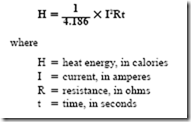
Direct Current Fundamentals defined a unit of energy measurement known as the joule. One joule is the energy expended by one ampere at one volt, in one second. Repeated experiments showed that when one ampere was passed through a resistance of one ohm for one second, 0.2389 or 0.24 calorie of heat was liberated. One calorie is the quantity of heat energy required to raise the temperature of one gram of water one degree Celsius. One calorie is equal to 4.186 joules (J). One joule, which is a unit of energy, is equal to one watt-second. For a dc circuit or an ac circuit with a heater unit, the heat in calories is found using the formula

image

In this formula, the I2 R term equals watts and I2 Rt equals the total energy in watt- seconds or joules. If 0.24 calorie (cal) is liberated for each joule of energy expended, the formula becomes

H = 0.24 I2 Rt

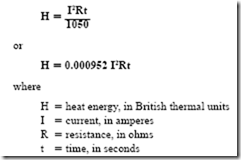
The calorie unit of the metric system is widely used. However, it is important that the stu- dent be familiar with another unit called the British thermal unit. The British thermal unit (Btu) is the amount of heat required to raise one pound of water one degree Fahrenheit. Because 1050 J is also required to raise one pound of water one degree Fahrenheit, 1050 J 1 Btu.

For a dc circuit or an ac circuit consisting only of a resistance load, such as a heater unit, the Btu developed in the circuit can be found using the formula

image

If the product in joules or watt-seconds in this formula is divided by 1050, the result is the heat energy in Btu. In the second form of the formula, the value in watt seconds is multiplied by the constant 0.000952. This constant is the decimal part of a Btu represented by one joule.

AVERAGE CURRENT AND VOLTAGE

Almost all alternating-current circuits and calculations use the effective or RMS values of the current and voltage. For example, ac voltmeters and ac ammeters indicate effective values. These values are 0.707 of the instantaneous maximum values.

There are some applications in which the average values of current and voltage are necessary. Some of these include rectifier units that use solid state devices such as diodes and silicon controlled rectifiers (SCRs) to convert alternating current into direct current.

Determining the Average Value

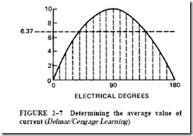
It was pointed out earlier that if an attempt is made to determine the average value of either a sine wave of voltage or current, the obvious procedure is to determine the aver- age value of one alternation of a sine wave. This can be done by taking the average of the ordinates (values on the Y axis) at fixed increments in electrical degrees for one alternation. Figure 2–7 shows the ordinates at 10° intervals for 180° or one alternation.

Another method of determining the average value of a sine wave is to measure the area of the alternation between the wave and the zero reference line. A device called a planimeter is used to measure this area. If the area is then divided by the length of the baseline and multiplied by the ordinate scale, the result will be the average value of the alternation.

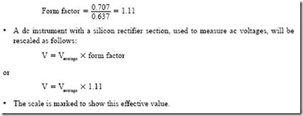
As shown in Figure 2–7, the average value of the maximum instantaneous value of a sine wave is 0.637. Because the effective or RMS value is 0.707 of the maximum value, a ratio can be made between the effective value and the average value. This ratio is 0.707 –: 0.637 1.11. This value is called the form factor and is equal to the effective value divided by the average value.

Full-Wave Rectifier

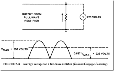
Figure 2–8 shows a resistance-type load connected across the output of a full-wave rectifier. The full-wave rectifier causes both alternations of the cycle to be above the zero reference line in a positive direction. Even though the voltage and the resultant current at the resistance load are pulsating, they do not reverse direction. If a dc voltmeter is

image

image

connected across the resistance load, as shown in Figure 2–8, the meter will indicate a value of 0.637 of the instantaneous maximum voltage. The dc voltmeter has a d’Arsonval movement, which operates on the same principle as a dc motor. This means that the deflection of the needle is determined by the average torque exerted on the movement for a time period of 360 electrical degrees. The resulting indication is the average value for the two alternations.

If the instantaneous maximum value of both alternations in Figure 2–8 is 350 V, then the average value indicated by the voltmeter is

image

Half-Wave Rectifier

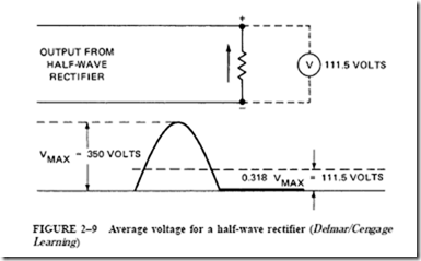
Half-wave rectifiers (Figure 2–9) eliminate one half of the waveform and retain the other. Depending on the rectifier, it could eliminate the negative half and retain the positive half or eliminate the positive half and retain the negative half. Regardless, the output of a half-wave rectifier consists of only one half of the 360° cycle. Compare this with the full- wave rectifier, which inverts both halves of the waveform. The example shown in Figure 2–9 assumes that the negative half of the ac waveform has been eliminated.

The resistance load shown in Figure 2–9 is connected to the output of a half-wave rectifier. For half of each time period of 360 electrical degrees, there is no voltage or cur- rent. Therefore, the voltmeter will indicate the average of the one alternation over the 360° time period. This average is half of 0.637, or 0.318.

If the circuit in Figure 2–9 has a maximum instantaneous voltage of 350 V, the volt- meter indication will be

image

image

Measuring AC Voltages

Some manufacturers of dc instruments modify the circuit connections and the scale calibrations to measure ac voltages and currents. Direct-current instruments have uniform scale graduations and markings for the entire scale range. AC voltmeters and ac ammeters lack this uniformity. Thus, it is sometimes difficult to obtain accurate readings. This is the case near the lower end of the scale because of the nonlinear scale graduations.

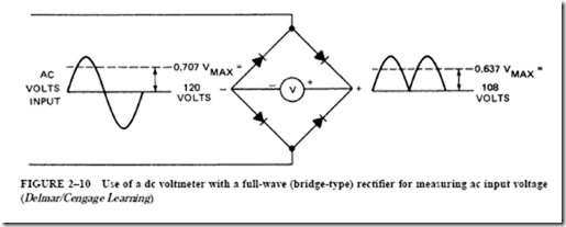
Figure 2–10 shows how ac voltages can be measured using a dc voltmeter with a full-wave bridge rectifier. The small rectifier section is contained within the instrument. In general, silicon rectifiers are used in meters. The rectifiers permit electron flow in one direction only. The full-wave dc output of the rectifier is impressed directly across the terminals of the dc voltmeter.

The dc voltmeter with a full-wave rectifier, shown in Figure 2–10, is connected across an ac voltage source. The instrument indicates 108 V. This value is an average value equal

image

to 0.637 of the instantaneous maximum value. If the losses in the rectifier can be neglected, then the actual effective value of ac voltage is

imageIn other words, the form factor of 1.11 is applied as a multiplier to the dc voltmeter reading to obtain the effective value of ac volts. To eliminate the need to multiply the average voltage value by the form factor to obtain the effective voltage, the instrument is rescaled to read effective values. This is done by multiplying the original scale values by 1.11 and remarking the scale.

It is sometimes necessary to determine different values of voltage. The voltage ratings of solid state devices, for example, are given as PIV (peak inverse voltage) or PRV (peak reverse voltage). This is the value of voltage the device can withstand without being dam- aged. Both of these ratings list the peak value. AC voltmeters generally indicate the RMS value, not the peak value. If a solid state component is to be connected into an ac circuit, it is generally necessary to determine the peak value to make certain the component will not be damaged.

PROBLEM

Statement of the Problem

A diode is used as a half-wave rectifier. The diode has a PIV rating of 150 volts. Can it be connected to a 120-V RMS circuit without damage?

Solution

Determine the peak value of the ac circuit.

image

The diode will be damaged if it is connected to the 120-V ac line.

The chart in Figure 2–10 can be used to determine different voltage values.

SUMMARY

• An incandescent lighting load and a heating load, such as a heater element, are noninductive resistive loads. For a circuit with such a load, the current waveform is in phase with the voltage waveform.

In phase means that the current and the voltage waveforms of a circuit are zero at the same time and reach their maximum values at the same time and in the same direction.

• Ohm’s law may be applied directly to ac circuits having a resistive load.

• In a resistive ac circuit, inductance, hysteresis effects, and eddy current effects may be neglected.

• Alternating current must be measured using an ac ammeter. All standard ac ammeters and voltmeters indicate effective or RMS values.

• The relationship between maximum and effective values is

image

• The effective value of ac is based on its heating effect and not on the average value of a sine-wave pattern.

• An effective ac current of one ampere will produce heat in a given resistance at the same rate as one ampere of direct current.

• The heating effect of ac varies as the square of the current (watts I2 R).

• The product of the effective voltage and the effective current in amperes gives the power in watts in ac circuits when the current and voltage are in phase.

• Instantaneous values of current can be squared and plotted to give a curve of current- squared values for one cycle. The resulting curve is the power curve. All current-squared values are positive. (Recall that when two negative numbers are multiplied, the product is positive.)

• The power curve gives the instantaneous power in the circuit at any point in the 360° time period of one cycle.

• Because the current squared value is always positive and indicates the instantaneous power available in the circuit, the load takes power (in watts) from the source of supply during the complete cycle.

• The average power in watts of an ac circuit may be less than the product of the voltage and current. (In circuits containing other than pure resistance, the energy formulas must be modified.)

image

(In circuits containing other than pure resistance, the energy formulas must be modified.)

• One joule is the energy expended by one ampere at one volt, in one second.

• One calorie is the quantity of heat energy required to raise the temperature of one gram of water one degree Celsius.

• Relationships between joules, calories, and watt-seconds are as follows:

image

• Average values of current are used by rectifiers, vacuum-tube units, and dc instruments used with silicon rectifiers to measure ac values.

• A d’Arsonval movement operates on the same principle as a dc motor. The deflection of the needle is determined by the average torque exerted on the movement for a period of 360 electrical time degrees.

• DC instruments have uniform scale graduations and markings for the entire scale. AC instruments have nonlinear scale graduations with inaccuracies toward the lower end of the scale.

• An ac instrument indicates the effective value on the scale (0.707 X maximum value).

A dc instrument with a silicon rectifier section, used to measure ac, will indicate the average value (0.637 X maximum value). Therefore, the dc instrument must be rescaled using a form factor multiplier.

• Form factor is a ratio between the effective value and the average value:

image

clip_image013clip_image013[1]

Achievement Review

1. Explain what is meant by the term effective current.

2. Show how the term root-mean-square current was derived.

3. An ac voltmeter connected across the terminals of a heating element of an electric stove indicates a value of 240 V. What is the maximum instantaneous voltage impressed across the heating element?

4. An ac sine wave has an instantaneous maximum value of 7 A. What is the indication of an ac ammeter connected in this circuit?

5. A noninductive heater element with a resistance of 60 D is supplied by a voltage that has a pure sine-wave shape. The instantaneous maximum value of the voltage is 120 V.

a. What is the instantaneous value of the voltage 30° after the voltage is zero and increasing in a positive direction?

b. What is the effective value of the current?

c. Show the relationship between the voltage and current sine waves for one complete cycle.

6. In question 5, what is the power in watts taken by the heater unit?

7. What is meant by the term in phase?

8. In question 5, what is the instantaneous value of current in amperes at 270 electrical degrees?

9. Twenty-four incandescent lamps are connected in parallel across a 120-V, 60-Hz supply. Twenty of the lamps are rated at 60 W, 120 V. Each lamp has a hot resistance of 240 D. The remaining four lamps are rated at 300 W, 120 V. Each of these lamps has a hot resistance of 48 D. (Assume that the incandescent lamps are pure resistance.)

a. Find the total current in amperes.
b. What is the total power in watts?

10.a. If the load in question 9 is operated 5 h each day during a 30-day billing period, what is the total energy consumed in kilowatt-hours?

b. What is the total cost at $.04 per kilowatt-hour to operate the lighting load for the 30-day billing period? 

11. A noninductive heater element with a resistance of 5 D is connected across a 60-Hz source. The supply has a sine-wave voltage with an instantaneous maximum value of 141.4 V.

a. Determine the power in watts taken by the heater unit.

b. What is the energy, in kilowatt-hours, taken by the heater unit in one month if it is operated 5 h per day for a period of 20 days?

12. The nameplate rating of an electric iron is 120 V, 10 A. The heating element of this appliance is almost pure resistance with the current and voltage in phase.

a. Determine the power in watts taken by the appliance.

b. Calculate the resistance of the heater element.

13. Define (a) calorie; (b) British thermal unit (Btu).

14. It is desired to raise the temperature of one quart of water in a coffee percolator from 18°C to 100°C in 9 min. The supply voltage is 120 V.

a. What is the wattage required by the heater unit to bring the water to a boiling temperature in 9 min?

b. What is the resistance of the heater unit?

c. Determine the current taken by the heater unit.

[Note: one quart of water 2.08 pounds (lb); 453.6 grams (g) 1 lb.]

15. An electric hot-water heater is used to heat a 20-gallon (gal) tank of water from 60°F to 130°F in 100 min.

a. Determine the wattage rating of the heater unit

b. Assuming that the heater unit is used on a 230-V, 60-Hz service, find

(1) the current in amperes taken by the heater unit.

(2) the resistance of the unit.

16. When does the product of effective volts and effective amperes equal the power in watts in an ac circuit?

17. A full-wave rectifier supplies a pulsating dc voltage similar to the one shown in Figure 2–8. A voltmeter connected across the noninductive resistance load reads 250 V. What is the instantaneous maximum voltage impressed across the load?

18. Explain what is meant by the term form factor.

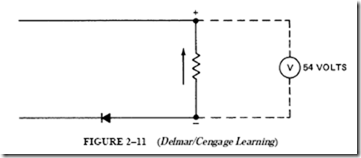
19. In Figure 2–11, a half-wave rectifier with a negligible resistance supplies a noninductive resistance load. A dc voltmeter connected across the load reads 54 V.

a. Determine the instantaneous maximum voltage.

b. What is the effective ac input voltage?

image

20. Show the type of rectified dc voltage that would be impressed across the load resistance in question 19.

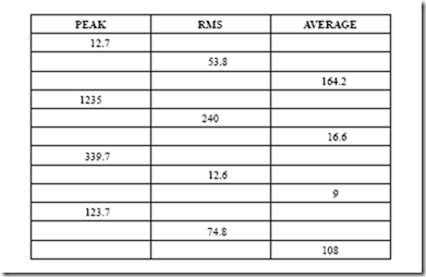
PRACTICE PROBLEMS FOR UNIT 2 Peak, RMS, and Average Values

Find the missing values.

image


Inductance in Alternating-Current Circuits : Review of electromagnetism and Inductive reactance.

Inductance in Alternating-Current Circuits

REVIEW OF ELECTROMAGNETISM

Direct Current Fundamentals discussed the following two basic principles of electro- magnetism: (1) a magnetic field surrounds every current-carrying conductor or coil winding, and (2) an increase or decrease in the current causes an increase or decrease in the number of lines of force of this magnetic field.

A changing magnetic field induces a voltage in the conductor, coil, or circuit. This voltage is proportional to the rate of change of the lines of force cutting across the conductor, coil, or circuit. In a direct-current circuit, there will be no inductive effect once the cur- rent reaches the value defined by Ohm’s law and remains constant. However, if the current changes in value, inductance does have a momentary effect. For example, if the current increases, more lines of flux will link the turns of wire in the coil winding. This change in flux linkage will cause a momentary induced voltage that opposes the increase in current. If the current decreases, there will be a decrease in the lines of flux linking the coil, resulting in a momentary induced voltage that attempts to maintain the current. These inductive effects are explained by Lenz’s law, which states:

In all cases of electromagnetic induction, the induced voltage and the resulting current are in such a direction as to oppose the effect producing them.

Inductance in a DC Circuit

The effect of inductance in a direct-current circuit can be shown using the circuit in Figure 3–1.

This circuit consists of a group of lamps connected in series with a coil of wire mounted on a laminated steel core. (This coil has a relatively low resistance.) When the circuit is energized from a 120-V dc supply, a short amount of time passes before the lamps shine at full brightness. Also, the needle of the dc ammeter moves upscale to the Ohm’s law value of current at a rate that is much slower than in a circuit containing only resistance. As the current increases to its Ohm’s law value, more and more lines of force link the turns of the coil to form a magnetic field. This increasing flux causes an induced voltage that opposes the impressed voltage (120-V supply) and limits the current in amperes. This circuit situation is a typical example of Lenz’s law in operation.

image

Current in an Inductive DC Circuit

Figure 3–2 shows the current increasing to its Ohm’s law value. Also shown is the momentary induced voltage for the circuit of Figure 3–1. At the instant the switch is closed, the current rises rapidly. Note, however, that the rate of current rise decreases with time. When the current reaches its Ohm’s law value, the rate of increase becomes zero. At the same instant when the switch is closed and the circuit is energized, the induced voltage has its maximum value. At this time, there is the greatest rate of increase in the number of lines of force linking the turns of the coil. Thus, the maximum voltage is induced. As the rate at which the current rises decreases with time, the induced voltage also decreases. Finally, when the current reaches a constant (Ohm’s law) value, the lines of force of the magnetic field will reach a maximum, resulting in a maximum field value. The induced voltage will decrease to zero when the current reaches its constant value.

When the circuit switch is opened, there will be a noticeable arc at the switch contacts. As the current decreases to zero (Figure 3–3), the lines of force collapse back into the turns of the coil. The cutting action of the collapsing lines of force is in a direction opposite that of the increasing field (when its switch is closed). As a result, the induced voltage will be in the same direction as the decaying current. This voltage will attempt to maintain the cur- rent, resulting in an arc at the switch contacts.

The decay of current in an inductive circuit is shown in Figure 3–3. The curve profiles for the decay of current and voltage may vary considerably from those shown. The actual curve profiles will depend on the time required for the line switch contacts to open.

A special switching arrangement must be used in the series circuit to observe the decay of the current and voltage. For example, assume that a single-pole switch is connected across the line wire of the series circuits in Figure 3–1. This switch closes at the instant the line switch contacts open. The length of time required for the current to decay to zero will equal the time required for the current to rise to its Ohm’s law value when the circuit is energized.

image

In Direct Current Fundamentals, it was shown that inductance is really a form of electrical inertia. Inductance is the ability of a circuit component, such as a reactor coil, to store energy in the electromagnetic field. The unit of inductance is the henry. The symbol for the henry is “H.” A henry is defined as follows:

A henry (H) is the inductance of a circuit, or a circuit component, when a current change of one ampere per second induces a voltage of one volt.

The Series Circuit Connected to an AC Supply

If the series circuit shown in Figure 3–1, consisting of a reactor coil and lamps, is connected to a 120-V, 60-Hz alternating-current supply, the lamps will be very dim. An ac ammeter connected into the circuit will show an effective current value that is lower than that of the current in the dc circuit. This condition applies even though the effective value of the ac voltage is the same as that of the dc source. Also, the resistance of the lamps is almost the same as in the dc circuit. The current reduction indicated by the ammeter reading and the dim lamps is caused by the “choking” effect of inductance in an ac circuit.

The alternating current supplied by the 60-Hz source is changing in magnitude and direction continually. As a result, a countervoltage is induced in the coil. This voltage opposes the impressed voltage and thus limits the current in the series circuit.

To demonstrate that the inductive effect shown in the dc circuit is the cause of the current reduction, the laminated core is slowly removed from the coil. As the core is withdrawn from the coil, the lamps will increase in brightness and the ammeter read- ing will increase. When the core is completely removed, the reluctance of the magnetic circuit of the coil will increase. This means that there is less flux rising and collapsing around the turns of the coil. Thus, the induced voltage decreases. If the core is replaced in the coil, the lamps will dim again and the ac ammeter reading will decrease. If the frequency of the ac source is reduced from 60 Hz to 25 Hz and the effective value of the line voltage is the same, the current will increase. As a result, the ammeter reading will increase and the lamps will be brighter. The lower frequency means that there are fewer cycles per second. Thus, there are fewer changes of current and lines of force per second. The induced or counter voltage in the coil will be less, resulting in an increase in the current.

It can be seen from this discussion that inductance in an alternating-current circuit is just as effective in limiting the current as resistance. This means that both inductance and resistance must be considered in any calculations for ac circuits.

INDUCTIVE REACTANCE

The repeated changes in the direction and magnitude of alternating current give rise to an induced voltage, which limits the current in an inductive circuit. This opposition due to the inductance is called inductive reactance. Inductive reactance is indicated by the symbol X

and is measured in ohms.

The inductive reactance in ohms can be found by the use of the formula

image

Problem in Inductive Reactance

To illustrate the use of the formula for inductive reactance, assume that a coil has an inductance of 0.2652 henry (H) and negligible resistance. This coil is connected across a 60-Hz supply with an effective voltage of 100 V, as shown in Figure 3–4. Determine the inductive reactance of the coil in ohms and also determine the current.

The inductive reactance of the reactor coil in the figure is as follows:

image

For a frequency of 60 Hz, it is an accepted practice to assume that the product of 2’ITf is 377 rather than 376.8. For a frequency of 25 Hz, the product of 2’ITf is 157. These values are convenient and may be used in the inductive reactance formula.

The current in the reactor coil of Figure 3–4 is found using the expression

image

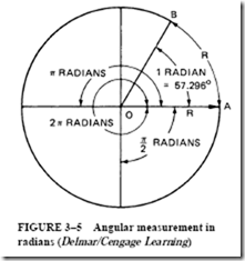
 The symbol w is the lowercase Greek letter omega. It represents angular velocity. Before angular velocity is defined, it is important to review the meaning of the term radian.

image

Measurement in Radians

The radian is a unit of angular measurement. This unit is sometimes used in place of electrical time degrees. The definition of the radian is as follows:

One radian is equal to the angle at the center of a circle, subtended by an arc whose length is equal to the radius.

In Figure 3–5, the length of the arc AB is equal to the radius R, or OA. By definition, the angle AOB is equal to one radian and is slightly less than 60°. (Actually, one radian is 57.296°.) The diameter of a circle multiplied by ‘IT equals the circumference of the circle. The circumference of a circle can also be obtained by multiplying the radius of the circle by 2’IT. Thus, the actual angle represented by a radian is 360 –: 2’IT = 57.296°.

One cycle is equal to 360 electrical time degrees. The circle shown in Figure 3–5, while illustrating angular measurement in radians, also represents 360°. Recall that the number of cycles per second is the frequency (f). Therefore, 2’IT radians is the angular velocity per cycle of the rotating radius line. The angular velocity per second is represented by 2’ITf. The Y projection of the rotating radius line is the sine wave of frequency, f (see Figure 1–8). If w represents the angular velocity per second, then the formula for inductive reactance may be stated in either of the following forms:

image

Current in an Inductive Circuit

The reactor coil in Figure 3–4 consists of a 100-0 inductive reactance and negligible resistance. If this coil is connected across an ac potential of 100 V, the current will be one ampere. However, it will be seen that this one-ampere current lags

image

behind the voltage by 90 electrical degrees. Although this condition may not seem possible, a study of Lenz’s law and the behavior of the induced voltage with an increase of current in a coil connected to a dc source (Figure 3–2) shows that the current may well lag behind the voltage.

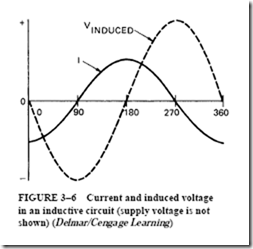
In an ac circuit containing only inductance, the current is opposed by the induced volt- age and thus cannot increase immediately with the impressed voltage. In Figure 3–6, the line voltage was omitted to make it easier to see the relationship between the alternating current and the induced voltage. The current is shown with its negative maximum value at the start of the cycle. At this point, and for a brief instant, there is no change in the current. Hence, there is no induced voltage. As the current decreases toward zero, the rate of change of current is increasing and the induced voltage increases. This voltage is represented by the dashed line.

The greatest rate of change of current for a given time occurs as it passes through zero. This means that the induced voltage has a maximum negative value at this same time. When the current passes through zero (at 90°) and increases to its positive maximum value, the rate of change of current is decreasing. As a result, the change in the lines of force in a given time period decreases proportionally and the induced voltage is reduced.

When the current reaches its positive maximum value at 180°, there will be a very brief period of time when there is no change in the current. For this period, the induced voltage is again zero. As the current decreases and passes through zero at 270° in a negative direction, the induced voltage reaches its positive maximum value. By developing the induced wave pattern for the remainder of the cycle, a sine wave of induced voltage is formed that lags behind the sine wave of current by 90 electrical degrees. To maintain the current in this coil, the line voltage applied must be equal and opposite to the induced volt- age. Obviously, if the applied line voltage is directly opposite to the induced voltage, then the two voltages are 180° out of phase with each other.

Figure 3–7 is similar to Figure 3–6, except that the impressed line voltage is also shown. It can be seen that the line voltage and the induced voltage are 180° out of phase. Note also that the current lags the line voltage by 90°.

image

When the current and the line voltage are both positive, energy is being stored temporarily in the magnetic field of the coil. Energy is also being stored in the magnetic field when both the current and the line voltage are negative. However, when the current is positive and the line voltage is negative, energy is returned from the inductor coil to the supply. This return of energy occurs because the current and voltage are acting in opposition. In those parts of the cycle where the line voltage is positive and the current is negative, energy is also released from the magnetic field of the inductor coil and returned to the supply. This energy released from the electromagnetic field of an inductor coil maintains the current when the voltage and current are in opposition.

The inductor coil circuit in Figure 3–4 has an inductive reactance of 100 0. The line voltage is 100 V and the current is one ampere. The line voltage can be plotted as a sine wave with a maximum value of 141.4 V. The line current lags the line voltage by 90 electrical degrees. The RMS value of current is one ampere, and the maximum current value is 1.414 A.

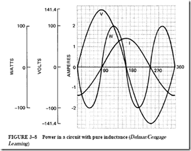
The power in watts at any instant is equal to the product of the volts and amperes at the same instant. Table 3–1 lists the instantaneous values of voltage, current, and power at 15° intervals for one complete cycle (360°) for this inductive circuit.

The wave patterns in Figure 3–8 were plotted using the values given in Table 3–1. Note that the current lags the line voltage by 90 electrical degrees. It is assumed that the reactor coil has no resistance and the circuit consists of pure inductance. Between 0° and 90°, the current is negative and the voltage is positive. Therefore, the product of volts and amperes for this part of the cycle gives negative power.

Between 90° and 180°, both the current and the voltage are positive. This means that there is a pulse of power above the zero reference line. This positive power indicates that the supply is feeding energy to the electromagnetic field of the coil.

In the period between 180° and 270°, there is a second pulse of negative power. This is due to the negative voltage and the positive current. The negative power pulse indicates that

image

image

energy stored in the magnetic field of the coil is released to the supply. This energy, which is stored momentarily in the coil, maintains the current in opposition to the line voltage.

Between 270° and 360°, both the current and the voltage are negative and are acting together. The product of these negative values results in positive power, as shown by the last power pulse for the cycle in Figure 3–8. Because the power pulse is above zero, energy is being supplied by the source to the reactor coil.

The power waveform in Figure 3–8 shows that the areas of the two positive pulses of power are equal to the areas of the two negative pulses of power. Keep in mind that the pulses of power above the zero reference line are positive power that is fed by the source to the load. The pulses of power below the zero reference line are called negative power. These pulses represent power that is returned from the load to the source. The assumption is made that the areas of the two positive pulses of power are

image

equal to the areas of the two negative pulses of power. This means that the net power taken by the inductor coil at the end of one complete cycle, or any number of cycles, is zero.

The actual power in watts taken by this circuit is zero. It should be noted that the product of the effective voltage and the effective current in amperes may not equal the power in watts in any circuit containing inductive reactance.


Series Circuits—Resistance and Impedance : Figure of merit

FIGURE OF MERIT

It has been pointed out that inductor coils have some resistance. For commercial coils, the inductive reactance is the useful component. The effective resistance is the unwanted component, which must be held to as low a value as possible. The ratio of the inductive reactance in ohms to the effective resistance in ohms is called the figure of merit. The symbol for the figure of merit is the letter Q.

The expression for the figure of merit is

image

A large Q (high figure-of-merit value) is desirable because it means that the useful inductive reactance is high and the effective resistance is low. A low value of Q means that the resistance component is relatively high. As a result, there is a large power loss.

image

By referring to the expressions for the figure of merit (Q), it can be seen that an increase in frequency will cause an increase in the inductive reactance and in the effective resistance. However, the inductive reactance and the effective resistance do not increase in the same ratio with an increase in frequency. Thus, the figure of merit (the Q of an inductor coil) must be determined for the frequency, or band frequencies, at which the coil is to be used.

For example, a 0.2-H inductor coil has a resistance of 100 n and is used at a frequency of 10,000 Hz. What is the Q of this coil?

image

Reactors that have a high Q value are often treated as pure inductors, and the amount of wire resistance is ignored because it is such a small part of the total impedance of the coil. For example, assume that an inductor has a Q of 10. This indicates that the amount of inductive reactance is 10 times greater than the wire resistance. In the following example, it will be assumed that an inductor has a wire resistance of 10 n and an inductive reactance of 100 n. When the total impedance of the coil is computed, it will be seen that the actual amount of wire resistance is only a small part of the coil’s total impedance:

image

PROBLEM 3

Statement of the Problem

Refer to Figure 4–13. It will be assumed that the inductor has a high Q value and contains zero resistance. The circuit contains 30 n of resistance and 40 n of inductive reactance and is connected to a 240-V, 60-Hz line. Refer to the formulas in the Resistive Inductive (Series) section of Appendix 15 to find the following unknown values:

1. Total circuit impedance (Z)

2. Current flow (I)

3. Voltage drop across the resistor (VR )

4. Watts, true power (P)

5. Inductance of the inductor (L)

6. Voltage drop across the inductor (VL )

7. Volt-amperes-reactive, reactive power (VARs)

8. Volt-amperes, apparent power (VA)

9. Power factor (PF)

10. Phase angle, which indicates how many degrees the voltage and current are out of phase with each other (Le)

Solution

image3. In a series circuit, the current is the same at any point in the circuit. Therefore,  4.8 A of current flows through both the resistor and the inductor. The amount of voltage dropped across the resistor can be computed by using the following formula:

image

4. True power for the circuit can be computed by using any of the power formulas. The following formula is used in this example:

image

image

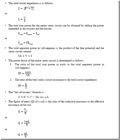
9. Power factor is the ratio of true power compared to apparent power. It can be computed by dividing any resistive value by its like total value. For example, the power factor can be computed by dividing the voltage drop across the resistor by the total circuit voltage, or resistance divided by impedance, or watts divided by volt-amperes. The power factor is generally expressed as a percentage. The decimal fraction computed from the division will, therefore, be changed to a percent by multiplying it by  100. In this circuit the following formula is used:

image

10. The power factor of a circuit is the cosine of the phase angle. The phase angle indicates how many degrees the current and voltage are out of phase with each other. Because the power factor of this circuit is 0.6, angle theta is as follows:

image

SUMMARY

• The resistance of a circuit or component to ac is the effective resistance.

• Impedance is the quantity resulting from the combination of effective resistance and reactance.

• Skin effect is the action whereby alternating current is forced toward the surface of a conductor.

• Eddy currents are induced by the alternating magnetic field around a current-carrying conductor in any metal near the conductor.

1. Eddy current losses occur in the iron cores of reactors, transformers, and stator windings in ac generators and motors.

2. Eddy currents are minimized by laminating the cores used in ac equipment.

• Hysteresis losses are caused by a constantly changing magnetic field due to ac.

1. The molecules of the core structure or other metallic material near the conductors of an ac circuit also change direction as the field changes. The result of these changes is molecular friction.

2. Power is required to overcome this molecular friction.

3. Hysteresis loss occurs as heat in the metallic structure.

• Dielectric loss is a small heat loss in the insulation.

1. The insulation of a conductor is subjected to a voltage stress as the impressed voltage rises to a maximum value twice in each cycle.

2. Usually, this loss is so small it can be neglected.

• The effective resistance for an ac circuit is greater than the true ohmic resistance. Effective resistance consists of skin effect losses, eddy current losses, hysteresis losses, and dielectric losses and is represented by the symbol “R.” Power from the circuit is required to overcome the effective resistance.

• The effective (ac) resistance of a reactor can be found by using

image

• A silicon steel core placed in a coil instead of an iron core will greatly decrease the eddy current and hysteresis losses. As a result, the effective resistance of the reactor is decreased.

• In the high-frequency range, the effective resistance can be many times higher than the dc resistance.

• The vector resolution method yields a right triangle that can be solved using simple algebra. In this method, the vertical components should not be added algebraically to the horizontal components. The equation used with this method has the following form:

image

image

clip_image002[1]_thumb

Achievement Review

1. Determine the inductive reactance in ohms and the inductance in henrys for the coil shown in Figure 4–3.

2. Determine the inductive reactance in ohms and the inductance in henrys for the coil shown in Figure 4–4.

3. Explain why there are differences in the inductive reactance in ohms and the inductance in henrys in the results of questions 1 and 2, using the same coil.

4. Explain the difference between the true ohmic resistance and the effective resistance of ac components.

5. An electromagnet consists of a coil with a laminated core assembly. This device takes 6 A when connected to a 120-V dc source. When energized from a 120-V, 60-Hz ac source, the current is 2 A. A wattmeter indicates 100 W.

a. Determine

(1) the true ohmic resistance of the coil.

(2) the effective resistance of the coil.

b. Explain why there is a difference between the true ohmic resistance and the effective resistance values for the same coil winding.

6. Determine the following values for the electromagnet coil in question 5:

a. The impedance

b. The inductive reactance

c. The inductance

d. The power factor

7. Explain why the current taken by the electromagnet coil in question 5 decreased from 6 A at 120 V dc to a value of 2 A when connected to a 120-V, 60-Hz ac source.

8. A series circuit containing a noninductive resistance of 3 n and a coil is connected to a 120-V, 60-Hz supply. The current is 25 A. The true power, as indicated by a wattmeter, is 2500 W. Determine

a. the power factor of the series circuit.

b. the effective resistance of the coil.

c. the impedance and inductive reactance for the coil.

d. the power factor of the coil.

9. Determine the following values for the circuit given in question 8:

a. The total circuit impedance

b. The total resistance of the circuit

10. Determine the following values for the circuit given in question 8:

a. The reactive power component for the coil

b. The reactive power component for the entire series circuit

c. The true power in watts taken by the coil

d. The true power in watts taken by the noninductive 3-n resistance

11. Draw a vector diagram for the circuit in question 8. Select convenient scales for the current and voltage. Label all vectors properly.

12. The temperature of a noninductive heater unit is controlled by a reactor. The heater unit and the reactor are connected in series across a 250-V, 60-Hz source. The voltage across the heater unit is 200 V. The voltage across the reactor is 100 V. The current in the circuit is 10 A.

a. Construct a vector diagram for the series circuit.

b. Determine

(1) the power factor of the series circuit.

(2) the power factor of the reactor.

(3) the impedance of the reactor.

(4) the effective resistance of the reactor.

(5) the inductive reactance of the reactor.

13. Determine the following data for the circuit given in question 12:

a. The impedance of the entire series circuit

b. The power expended in the heater unit, in watts

c. The power expended in the coil, in watts

d. The total power expended in the series circuit, in watts

e. The total apparent power taken by the series circuit, in watts

f. The reactive power component, in VARs, for the series circuit

14. Two reactors are connected in series across a 10-V, 10-kHz source. They are spaced so that there is no interaction between their electromagnetic fields. Coil 1 has an effective resistance of 200 n and an inductance of 200 millihenrys (mH). Coil 2 has an effective resistance of 300 n and an inductance of 10 mH.

Determine

a. the total resistance, in ohms.

b. the total inductive reactance, in ohms.

c. the total impedance, in ohms.

d. the current, in milliamperes.

e. the total true power expended in the series circuit, in watts.

15. Explain what is meant by the term figure of merit.

16. A coil has an inductance of 300 microhenrys (μΗ) and a figure of merit of 90 when operated at a frequency of 1500 kHz. Determine the effective resistance of the coil at this frequency.

PRACTICE PROBLEMS FOR UNIT 4

Resistive Inductive Series Circuits

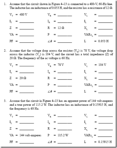
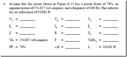
Find the missing values for the following circuits. Refer to problem 3 and the circuit shown in Figure 4–13.

image

image


Series Circuits—Resistance and Impedance : Effective resistance , Skin effect , Eddy current losses , Hysteresis losses and Dielectric losses.

Series Circuits — Resistance and Impedance
EFFECTIVE RESISTANCE

The effective resistance is the resistance that a circuit or component offers to alternating current. Also known as ac resistance, it may vary with the frequency, current, or voltage of the circuit. Effective resistance must not be confused with impedance. The quantity resulting from the combination of effective resistance and reactance is impedance.

SKIN EFFECT

Alternating current tends to flow along the surface of a conductor. Direct current acts through the entire cross-sectional area of the conductor in a uniform manner. The name skin effect is given to the action whereby alternating current is forced toward the surface of a conductor. Because of the skin effect, there is less useful copper conducting area with alternating current. As a result, there is an increase in resistance.

EDDY CURRENT LOSSES

Alternating current in a conductor or circuit sets up an alternating magnetic field. Eddy currents are induced by this field in any metal near the conductor. For example, eddy current losses occur in the iron cores of reactors, transformers, and stator windings in ac generators and motors. A reduction in eddy currents is achieved by laminating the cores used in ac equipment. However, there are small I2R losses in each lamination of the core.

HYSTERESIS LOSSES

In alternating current, the direction of current is constantly changing. This means that the lines of force of the magnetic field are also changing direction repeatedly. In other words, millions of molecules reverse direction in the process of magnetizing, demagnetizing, and remagnetizing the structure of any iron core or other metallic material adjacent to the conductors of an ac circuit.

As these molecules reverse their direction with each change of magnetization, molecular friction results. Power is required to overcome this molecular friction. This loss occurs as heat in the metallic structure and is known as hysteresis loss. The ac circuit adjacent to the metallic material must supply the power in watts to overcome this hysteresis loss. All ac generators, ac motors, transformers, and other ac equipment experience hysteresis loss. To reduce this loss, special steels are used for the core structure. For example, silicon steel may be used because it has a relatively low molecular friction loss.

DIELECTRIC LOSSES

As the impressed voltage rises to a maximum value twice in each cycle, a voltage stress is placed on the insulation of the conductor. Such a stress occurs first in one direction and then in the other. As a result, there is a small heat loss in the insulation. This loss is called the dielectric loss and is very small when compared to the other losses in the circuit due to the skin effect, eddy currents, and hysteresis. Usually the dielectric loss can be neglected.

The losses just described all require the use of power supplied by the electrical circuit. The power in watts is expressed by the formula P = I2 R. This formula can be rearranged to find the resistance: R = P –: I2. Thus, if the power increases while the current remains the same, the effective resistance increases.

For ac circuits, “R” represents the effective ac resistance. The dc resistance, or the true ohmic resistance, in an ac circuit may be designated as “R .”

image

Representing DC and Effective (AC) Resistance

Figure 4–1 shows an impedance triangle. The base of the triangle represents the effective resistance. This resistance is divided into five parts representing the true dc resistance and the four losses just described.

Problem in DC and AC Resistance

A practical circuit problem can be used to compare the meanings of the true ohmic (dc) resistance and the effective (ac) resistance. Figure 4–2 shows a reactor coil (reactor), with a laminated silicon steel core, connected to a dc source.

image

The pure ohmic resistance of the reactor can be measured using the ammeter– voltmeter method. A bank of lamps is inserted in series with the reactor to limit the current to a safe value. The true ohmic resistance of the reactor in Figure 4–2 is

image

The iron core is now removed from the reactor, which is connected to a 120-V, 60-Hz source, as shown in Figure 4–3. This circuit does not require a current-limiting resistor connected in series with the reactor. Because the reactor is energized from an ac source, there is enough inductive reactance in the reactor to limit the current to a safe value. As a result, the bank of lamps is removed from the circuit.

Using the values given in Figure 4–3, the effective (ac) resistance of the air core reactor is

image

It has been determined that the dc (true ohmic) resistance is 0.25 n. The effective ac resistance is 0.33 n. The slight increase in effective resistance compared to the dc resistance is due to the skin effect and dielectric losses.

The reactor shown in Figure 4–4 has a laminated iron core. The power increases from 8.25 to 16 W, even though the current decreases from 5 to 4 A. This means that the effective resistance increased.

image

image

Increase of Effective (AC) Resistance. The increase in the effective (ac) resistance from

to 1 n is due to the eddy current and hysteresis losses in the steel core. The addition of the laminated core to the reactor results in a greater power loss in the reactor because of the skin effect and the dielectric, eddy current, and hysteresis losses. The increased power loss means there is also an increase in the effective resistance. Recall that the true ohmic resistance of the reactor is 0.25 n.

When the laminated core of the reactor is replaced with a solid cast-iron core (Figure 4–5), the voltage is still 120 volts and the current is 4.5 A. However, the wattmeter shows that there is a great increase in the power expended in the coil. Why does the power increase with a solid cast-iron core?

The constantly changing field induces voltages in the solid core. The resulting eddy currents have a low-resistance circuit path and are higher in value. Thus, the I2R losses are greater. In addition, the hysteresis loss (molecular friction loss) is greater in the cast-iron core than in the silicon steel core. These increases in the eddy current and the hysteresis losses mean that more true power in watts is delivered to the reactor. As a result, the effective resistance of the reactor for this circuit increases:

image

Effect of Higher Frequencies on AC Resistance. The effective resistance of alternating- current equipment at low frequencies, such as 60 Hz, can be several times greater than the true ohmic resistance. In the high-frequency range, the effective resistance can be many times higher than the dc resistance. This increased resistance is due to the fact that the skin effect, dielectric losses, eddy current losses, and hysteresis losses all increase with an increase in frequency.

clip_image012

FIGURE 4–5 Reactor coil (with solid cast-iron core) connected to ac source (Delmar/Cengage Learning)

Table 4–1 summarizes the resistance, reactance, and current ranges for various circuits.

image


Capacitors and RC Time Constants : Introduction and Capacitance.

Capacitors and RC Time Constants
INTRODUCTION

Direct Current Fundamentals explained how a material is a conductor or an insulator because of its atomic structure. It was stated that electrons are loosely held in the outer electron shells of each atom of a good conductor such as copper. Only a small force is required to dislodge these electrons. Good conductors have many free electrons in their structure.

image

A characteristic of insulating materials is that their electrons are firmly held in the electron shells of each atom of the material. A great deal of force is required to remove these electrons. Insulating materials have few free electrons in their structure.

The Elementary Capacitor

If an insulating material, known as a dielectric, is placed between two plates of a con- ducting material, the resulting assembly is an elementary capacitor.

In Figure 5–1, a simple capacitor is shown to consist of two metal plates separated from each other by a thickness of dielectric. Under normal conditions, with the capacitor deenergized, the electrons in the dielectric revolve in circular orbits around the nucleus of each atom.

Charging the Capacitor. The capacitor is shown connected to a dc voltage source in Figure 5–2. Electrons will flow from the negative side of the source to plate 2 and from plate 1 back to the source. This movement of electrons from negative to positive is the normal direction of electron flow.

Electrons will continue to move until the potential difference across the two metal plates is equal to the dc source voltage. When the potential and the voltage are the same, the flow will stop. There will be almost no flow of electrons through the dielectric (insulating) material between the plates. There will be a surplus of electrons on plate 2 and a deficiency of electrons on plate 1. The electrons in the atoms of the dielectric material will be attracted toward the positive plate and repelled from the negative plate. However, these electrons cannot flow from plate 1 to plate 2 because the electrons in a good dielectric material are firmly held in each atom.

image

Thus, the forces acting on the electrons cause their orbits in each atom in the dielectric to be distorted. As shown in Figure 5–3, the orbits form elliptical patterns.

The capacitor in Figure 5–3 is completely charged. The voltage across the capacitor plates is equal to the dc source voltage. Therefore, there is no electron flow. To simplify the figures, only three atoms are shown. In an actual capacitor, there are millions of atoms with distorted orbits in the dielectric.

If the capacitor is disconnected from the dc supply, the surplus electrons on the nega- tive plate are held to this plate by the attraction of the positive charge of the other plate. In other words, an electrostatic field effect is created by the charged plates. This effect maintains the distortion of the electron orbits in the atoms of the dielectric. The atomic distortion of the dielectric is an indication of the electrical energy stored in the capacitor.

If the voltage applied to the capacitor is too large, the electrons in the atoms of the dielectric will be pulled from their orbits. The insulating ability of the dielectric breaks down, and the energy stored in the capacitor is released. In the case of a solid dielectric material, such a breakdown destroys its usefulness and a shorted capacitor results.

image

image

Discharging the Capacitor. A resistor is now connected across the capacitor as shown in Figure 5–4. The capacitor discharges through the conducting resistor. Electrons on the negatively charged plate (plate 2) will leave the plate and will flow toward plate 1 through the resistor. This electron flow continues until they are distributed equally in the circuit. Then the flow of electrons stops. While the electrons flow, the electrical energy stored in the electrostatic field is being released from the dielectric of the capacitor.

As the electrons flow from the negatively charged plate, a change takes place in the electron orbits of each atom of the dielectric. That is, the orbits change from the distorted elliptical pattern (Figure 5–4) to their normal circular pattern (Figure 5–5).

Leakage Current

In theory, it should be possible for a capacitor to remain charged forever. In actual practice, however, it cannot. No dielectric is a perfect insulator, and over a period of time electrons will eventually move through the dielectric from the negative plate to the positive plate, causing the capacitor to discharge (Figure 5–6). This current flow through the dielectric is called leakage current and is proportional to the resistance of the dielectric and the charge across the plates. If the dielectric of a capacitor becomes weak, it will permit an excessive amount of leakage current to flow. A capacitor in this condition is referred to as a leaky capacitor.

CAPACITANCE

The Meaning of Capacitance

A capacitor can store electrical energy. It can also return this energy to an electric circuit. It is important to understand what the term capacitance actually means. Capacitance is the property of a circuit, or circuit component, that allows it to store electrical energy in electrostatic form.

image

The Measurement of Capacitance

Circuit components other than capacitors may create a capacitance effect. For example, when two wires of a circuit are separated by air, they will act as a capacitor. Also, adjacent turns of a coil winding, which are separated only by the insulation of the wire,

will have some capacitance effect. The standard unit of measurement for capacitance is the farad. This unit of measurement is defined as follows:

A capacitor has a capacitance of one farad when a change of one volt across its plates results in a charge movement of one coulomb.

The farad is too large a unit for a typical capacitor. A smaller unit, known as a microfarad, is commonly used. The microfarad is equal to 1 –: 1,000,000, or 10-6 farad. The letter symbol for the farad is F. The microfarad is indicated by the symbol p,F, where p, is the Greek letter mu.

Electronic circuits often require very small capacitors. In such cases, even the micro- farad is too large. A smaller unit of capacitance measurement is required. This unit is the picofarad. One picofarad is equal to 1 –: 1,000,000th of a microfarad, or 10-12 farad. The letter symbol for the picofarad is pF.

The capacitance of a capacitor can be increased by any of the following factors:

• Increasing the plate area, resulting in an increase in the area of the dielectric under stress

• Moving the metal plates closer together, resulting in a decrease in the thickness of the dielectric

• Using a dielectric with a higher dielectric constant

The Charge of a Capacitor

For a given applied voltage, the charge on the plates of a capacitor is directly proportional to the capacitance of the capacitor. The charge is measured in coulombs and is directly proportional to the charging voltage. If the charge on the plates is directly proportional to both the capacitance and the impressed voltage, then the charge is expressed as follows:

image

As an example of the use of this formula, assume that a capacitor takes a charge of 0.005 coulomb (C) when connected across a 100-V dc source. Determine the capacitance of the capacitor in microfarads:

image


Capacitors and RC Time Constants : Dielectric characteristics , Capacitance formulas and Capacitors in parallel.

DIELECTRIC CHARACTERISTICS

Three factors were shown to affect the capacitance of a capacitor. One factor is the type of insulating material used for the dielectric. Most capacitors are constructed using a dielectric material having a higher dielectric constant than air.

The dielectric constant of an insulating material measures the effectiveness of the material when it is used as the dielectric of a capacitor. It is assumed that air has a dielectric constant of one. If a two-plate capacitor has a dielectric consisting of paper impregnated

image

with paraffin, rather than a dielectric of air, the capacitance will increase. If the capacitance is doubled when using paper in place of air for the dielectric, the dielectric constant for paper is 2. This value indicates the degree of distortion of the electron orbits in the dielectric for a given applied voltage. Table 5–1 lists the dielectric constants of some insulating materials.

Dielectric Strength

If the voltage across the plates of a capacitor becomes too high, the dielectric may be burned or punctured by the high potential. That is, the high potential tears electrons from the orbits of the atoms of the dielectric material. As a result, the dielectric becomes a con- ducting material, resulting in permanent damage to the dielectric.

Dielectric materials are given a dielectric strength rating. This rating is stated as either “volts per centimeter” or “volts per mil” of thickness required to break down the dielectric. The dielectric strength rating is not the same as the dielectric constant rating. For example, the dielectric constant of paper is about 2 and that of Pyrex glass is approximately 4. However, the dielectric strength in volts per mil for some kinds of paper is about 1200 V. For Pyrex glass, the dielectric strength is only 325 V per mil.

CAPACITANCE FORMULAS

The capacitance of a two-plate capacitor is directly proportional to the area of one plate and inversely proportional to the distance of separation between the plates.

This statement can be expressed as a formula. Actually, there are two forms of the formula, depending on the units of measurement for the distances involved. To determine the capacitance in picofarads when the plate dimensions and the distance between the plates are given in inches, the formula is

image

PROBLEM 1

Statement of the Problem

A paper capacitor consists of two tinfoil plates, each 8 feet (ft) long and 1 inch (in.) wide. The waxed paper that separates the two plates has a thickness of 0.05 in. Determine the capacitance of the capacitor. The dielectric constant of waxed paper is 2.

Solution

image

CAPACITORS IN PARALLEL

In addition to increasing the plate area, an increase in capacitance can be obtained by increasing the number of plates in the capacitor.

The multiple plates of the capacitor shown in Figure 5–7 are placed so that a maxi- mum plate area is obtained. Note that alternate plates are connected in parallel. To calculate

image

the capacitance of a multiplate capacitor, where the plates are identical and are separated by the same distance, the following expression is used:

image

image