Series Circuits: Resistance, Inductive Reactance,and Capacitive Reactance : Resonance in series circuits and The properties of series resonance.

RESONANCE IN SERIES CIRCUITS

In the solution to problem 1 in this unit, the inductive reactance was greater than the capacitive reactance. As a result, there was a lagging power factor. In problem 2, the capacitive reactance is larger than the inductive reactance and the power factor is leading.

If the inductive reactance equals the capacitive reactance, then V equals V . Because these voltages are 180° out of phase with each other, they will cancel exactly. The effects of both the inductive reactance and the capacitive reactance are now removed from the

image

series circuit. Thus, only the resistance of the circuit remains to limit the current. A circuit for which these conditions are true is called a resonant circuit. The full line voltage appears across the resistance component.

PROBLEM 2

Statement of the Problem

A resonant series circuit is shown in Figure 7–6. The phase angle between the current and the line voltage for this circuit is zero. The power factor is 1.00.

Another way of looking at this circuit is to recognize that the value of the magnetizing VARs required by the coil is equal to the magnetizing VARs supplied by the capacitor. These values cancel each other so that no VARs appear at the input terminals.

Determine the following quantities for the resonant series circuit in Figure 7–6:

1. The impedance

2. The current

3. The voltage across the resistor

4. The voltage across the coil

image

5. The voltage across the capacitor

6. The loss in the resistor, in watts

7. The magnetizing VARs required by the coil

8. The magnetizing VARs supplied by the capacitor

9. The input in volt-amperes

10. The power factor and the phase angle for the series circuit Then develop the vector diagram for the circuit.

Solution

1. The impedance of a resonant circuit is the same as the resistance of the circuit. The formula for impedance is

image

image

3. The voltage across the total resistance of a resonant series circuit equals the line volt- age. It is assumed that there is no resistance in either the coil or the capacitor. The voltage across the lamp load is

image

image

9. The input volt-amperes for the series circuit is the product of the line voltage and the current. The input volt-amperes and the true power are the same in a series resonant circuit:

VA = VI = 120 X 5 = 600 VA

10. Because the true power and the input volt-amperes are the same for this circuit, the power factor is unity. A unity power factor is also obtained from the ratio of the resistance of the resonant series circuit and the input impedance:

image

THE PROPERTIES OF SERIES RESONANCE

Figure 7–8 summarizes the properties of series resonance. Each curve is based on the mathematics of series resonance.

image

image

Current versus Frequency (Figure 7–8C)

The impedance/frequency waveform of Figure 7–8B is useful in interpreting the cur- rent versus the frequency waveform in Figure 7–8C.

According to the equation I = V/Z, as the impedance rises, the current falls. The reverse is also true. This means that the current curve is the reciprocal or inverse of the impedance curve.

Graphically, it was convenient to use the impedance curve to explain the current curve. In the laboratory, however, it is easier to vary the frequency and note ammeter readings than it is to vary the frequency and calculate impedance values.

Power Factor versus Frequency (Figure 7–8D)

The formula that defines the power factor curve is PF = R/Z. This formula was selected because it lends itself to the impedance curve.

At frequencies below resonance, the equation PF = R/Z shows the power factor to be inversely proportional to impedance. For high values of impedance, where the frequencies are below resonance, the power factor becomes small. Therefore, for small values of R, it is possible to obtain a power factor near zero. The cosine of the phase angle is zero. Thus, the phase angle equals 90°. Because the frequency is below resonance, the circuit is capacitive, and the power factor is leading or positive.

For frequencies at resonance, Z = R. Thus, the equation PF = R/Z becomes unity.

The angle whose cosine is unity is 0°.

For frequencies above resonance, the equation PF = R/Z has the same values as it does when the frequencies are below resonance. In this case, the circuit is now inductive and the power factor is lagging or negative.

SUMMARY

• In an inductive circuit, the current lags the applied voltage across the inductor.

• In a capacitive circuit, the current leads the applied voltage across the capacitor.

• The net reactance of an RLC series circuit is

image

image

image

image

• The circuit power factor (PF) and the phase angle (ÐO) are determined by the resistance and the capacitive or inductive reactance that is not canceled.

• At the resonant frequency

1. The phase angle between the current and the line voltage is zero.

2. The power factor is 1.00, and the input volt-amperes and the true power are the same: VA = VI. Also,

image

image

image

Achievement Review

1. A series circuit consists of a 100-n resistor, a coil with an inductance of 0.5 H and negligible resistance, and a 40-µF capacitor. These components are connected to a 115-V, 60-Hz source.

a. Determine

1. the impedance of the circuit.

2. the current in the circuit.

3. the power factor and the phase angle of the circuit (indicating whether the power factor and the phase angle are leading or lagging).

b. Draw a vector diagram for the circuit.

2. A coil, having a resistance of 100 n and an inductance of 0.2 H, is connected in series with a 20-µF capacitor across a 120-V, 60-Hz supply. Determine

a. the impedance of the circuit.

b. the current.

c. the power factor of the circuit.

d. the voltage across the capacitor.

e. the instantaneous maximum voltage across the terminals of the capacitor.

3. In the series circuit shown in Figure 7–9, determine

a. the total impedance.

b. the voltage drop across the coil.

c. the capacitance required to obtain resonance.

image

4. a Explain what is meant by the term resonance when used with ac series circuits.

b. What precaution must be observed when working with series circuits having inductive and capacitive circuit components?

5. For the series circuit shown in Figure 7–10, determine

a. the frequency at which this circuit will resonate.

b. the value of the impedance of the circuit at resonance.

c. the power factor at resonance.

d. the voltage across the capacitor at the resonant frequency.

image

6. The starting winding circuit of a capacitor-start, induction-run motor consists of a 15-n resistance and a 20-n inductive reactance. These components are in series with a 50-j.LF capacitor. The circuit is connected to a 120-V, 60-Hz source.

Determine

a. the impedance of the series circuit.

b. the current.

c. the true power.

d. the power factor.

7. A simple tuning circuit consists of a 100-µH inductance, a 200-pF capacitance, and a 20-n resistance connected in series. The voltage from the antenna to ground is 100 µV.

a. Determine the resonant (natural) frequency of the circuit.

b. Determine the current, in microamperes, at the resonant frequency.

8. For the circuit given in question 7, determine the voltage across the coil at the resonant frequency.

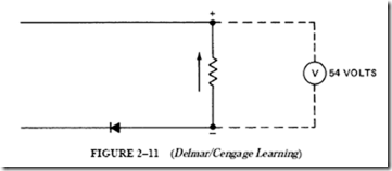
9. In the circuit shown in Figure 7–11, determine the voltmeter reading for each of the following conditions:

a. When point A is grounded

b. When the ground is removed from A and placed at B

c. When there is no ground at either point A or point B, but there is a “break” in the coil

image

10. For question 9, determine the voltmeter reading for each of the following conditions:

a. There is no ground at either point A or point B, and the coil and capacitor are in good condition, but the resistor is completely “shorted.”

b. There are no faults in the circuit.

11. A single-phase, 115-V, 60-Hz motor uses a 100-µF capacitor in series with the starting winding. The starting winding has an effective resistance of 5 n and an inductance of 0.01 H. Determine

a. the total impedance, in ohms, of the starting winding circuit, including the series-connected capacitor.

b. the current.

c. the voltage across the capacitor.

12. Draw a labeled vector diagram for the circuit in question 11.

13. A coil has a resistance of 100 n and an inductance of 0.2 H. This coil is connected in series with a 20-µF capacitor across a 120-V, 60-Hz supply. Determine

a. the total impedance of the series circuit.

b. the current.

c. the power factor and the power factor angle for the series circuit.

d. the impedance of the coil.

e. the power factor and the power factor angle for the coil.

14. Draw a labeled vector diagram for the series circuit in question 13.

image

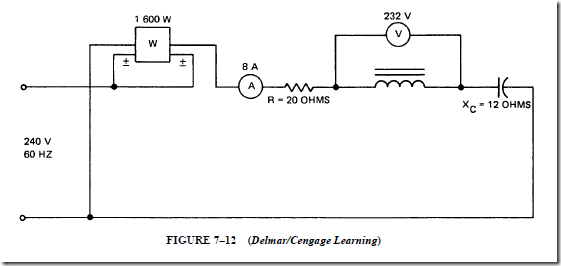
15. Using the values given on the circuit diagram in Figure 7–12, determine

a. the impedance of the coil.

b. the resistance of the coil.

c. the inductive reactance of the coil.

d. the power factor and the phase angle for the coil.

16. Using the circuit given in question 15, determine

a. the impedance of the entire series circuit.

b. the power factor and the power factor angle for the series circuit.

c. the loss in volts across the resistor and across the capacitor.

d. the inductance of the coil, in henrys.

e. the capacitance of the capacitor, in microfarads.

17. Construct a vector diagram for the circuit in question 16.

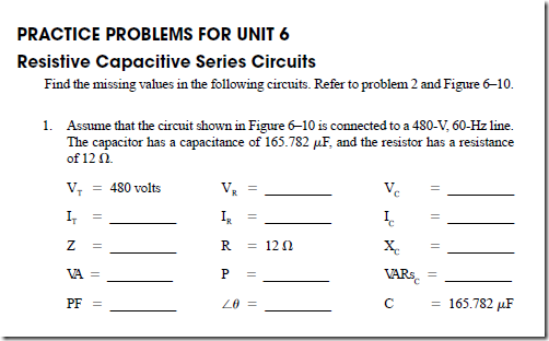
PRACTICE PROBLEMS FOR UNIT 7

Resistive, Inductive, Capacitive Series Circuits

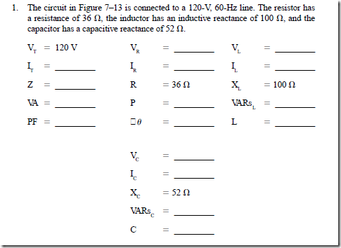
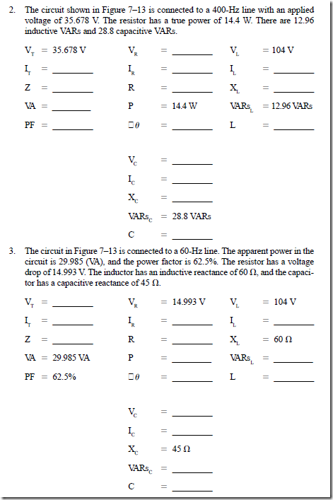
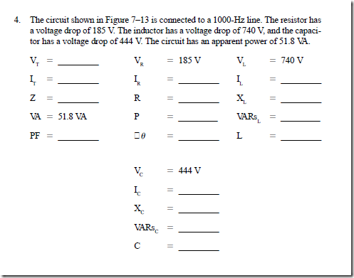
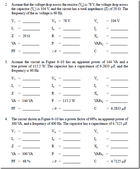
Find the missing values in the following circuits. Refer to Figure 7–13 and the formulas listed in the Resistance, Inductive, Capacitive (Series) section of Appendix 15.

image

image

image

image


Series Circuits: Resistance, Inductive Reactance,and Capacitive Reactance : Series RLC circuit

Series Circuits: Resistance, Inductive Reactance, and Capacitive Reactance
SERIES RLC CIRCUIT

Figure 7–1 shows a series circuit containing a resistor, an inductance coil with negligible resistance, and a capacitor. For this type of circuit, it is important to remember that

(1) the voltage (V) across an inductor (L) leads the current (I), and (2) the current (I) in a capacitor (C) leads the voltage (V).

This information can be expressed by means of a vector diagram, as in Figure 7–2.

The voltage component across the inductor (V ) is rotated counterclockwise so that it leads the current (I) by 90°. The current in the capacitor leads the voltage (VC) by 90°. The diagram shows that the voltage drops across the inductor and the capacitor are 180° out of phase (Figure 7–2A). This means that they oppose each other. When the components in the voltage vector diagram are divided by I, the resulting reactance vectors also oppose each other (Figure 7–2B).

Net Reactance of an RLC Series Circuit

The net reactance, in ohms, for an RLC series circuit is found by subtracting the capacitive reactance from the inductive reactance. For the circuit in Figure 7–1:

image

image

This example shows that 53.1 n of inductive reactance is canceled by the 53.1 n of capacitive reactance. The difference of 60 n represents the inductive reactance that affects the operation of the series circuit.

Impedance of the RLC Series Circuit

Impedance is the result of the combination of resistance and reactance. In Figure 7–1, the impedance is the combination of the resistance of 40 n and the difference between the inductive reactance and the capacitive reactance. The impedance for this circuit is

image

Voltage Drop across the Elements

The voltage drops across the resistor, the inductor coil, and the capacitor are deter- mined as follows:

Voltage drop across R:

image

Voltage drop across L:

image

Voltage drop across C:

image

Vector Diagram of the Series RLC Circuit

The vector diagram for the series RLC circuit of Figure 7–1 is shown in Figure 7–3. V is shown in the positive Y direction, and V is shown in the negative Y direction. The magnitude of V – VC is found by means of the vector addition rule of placing vectors head to tail. Thus, the V vector is placed on top of the V vector (head to tail) to find the difference: V – VC = 200 V. It is important that the student understand that the vectors were not subtracted to equal 200 V, but were added.

The vector sum of the voltage across the resistor, 133.2 V, and the voltage across the net inductive reactance, 200 V, is equal to the line voltage, 240 V:

image

Power Factor of the Series RLC Circuit

The power factor of this type of circuit can be determined by any of the methods used in previous series circuit problems. The power factor of this circuit is

image

Because the inductive reactance is greater than the capacitive reactance, this series circuit has a lagging power factor. The power factor has a lagging phase angle of 56.3°. This means that the current lags the line voltage by 56.3°, as shown in Figure 7–3.

image

PROBLEM 1

Statement of the Problem

For the circuit in Figure 7–1, the inductive reactance is greater than the capacitive reactance. For the circuit in Figure 7–4, the capacitive reactance is more than the inductive reactance.

This series circuit consists of three components: a noninductive 20-n resistor, an inductance coil having an inductance of 0.1 H and negligible resistance, and a 50-µF

image

capacitor. These components are connected to a 120-V, 60-Hz source. Figure 7–4 also shows the relationship between the line current and voltage waveforms across each component. The voltage across the resistance is in phase with the current, the voltage across the inductor coil leads the current by 90°, and the voltage across the capacitor lags the current by 90°.

The following circuit values are to be determined for this series RLC circuit:

1. The impedance

2. The current

3. The voltage across (a) the resistor, (b) the coil, and (c) the capacitor

4. The line voltage (check)

5. The true power, in watts, taken by the series circuit

6. The magnetizing VARs required by the coil

7. The magnetizing VARs supplied by the capacitor

8. The net magnetizing VARs supplied to the power source

9. The input volt-amperes for the series circuit

10. The circuit power factor and the phase angle

Solution

1. The inductive reactance equals 21TfL, and the capacitive reactance equals

image

Therefore, the impedance formula can be stated in either of these forms:

image

image

If the capacitive reactance is greater than the inductive reactance, the quantity in parentheses in the formulas is negative. Because the square of a negative number is

image

4. The voltage across the capacitor is greater than the voltage across the coil. These two voltages are 180° out of phase and oppose each other. Subtracting these voltages yields

252.52 – 179.45 = 73.07 V

This means that the part of the capacitor voltage that is not canceled by the coil volt- age is equal to 73 V. The vectorial addition of 73 V and the loss across the resistor,

95.2 V, gives the line voltage, or 120 V. The line voltage can be determined using the right-triangle method, in which

image

5. The true power, in watts, taken by the series circuit can be determined by

image

image

image

8. The net magnetizing VARs supplied to the source is the difference between the VARs supplied by the capacitor and the VARs required by the coil: 1202 – 854 = 348 VARs. The net magnetizing VARs can also be calculated using the net reactance

(15.35 n capacitive) and the net reactive voltage (73.07 V):

image

10. There are three methods of calculating the power factor of the series circuit:

image

The capacitive reactance is greater than the inductive reactance of this circuit. This means that all of the inductive reactance is canceled. The circuit power factor and the phase angle are determined by the resistance and the capacitive reactance that is not canceled by the inductive reactance. As a result, the series circuit has a leading power factor. The current leads the line voltage by a phase angle of 37.5°.

Voltage and Current Vector Diagram

A voltage and current vector diagram is shown in Figure 7–5 for the series circuit of Figure 7–4. The two reactance voltages are 180 electrical degrees out of phase. Because the voltage across the capacitor is larger, the voltage across the coil is subtracted from V . The difference of V – VL is combined by vector addition with the voltage across the resistor to give the line voltage. The current leads the line voltage in a counterclockwise direction by 37.5°.


Capacitors in Alternating-Current Circuits : Capacitors in parallel and in series , Magnetizing VARs and Diagrams for the series circuit

CAPACITORS IN PARALLEL AND IN SERIES

Unit 5 explained the methods used to compute the total capacitance for capacitors connected in parallel and in series. Figure 6–4 shows three capacitors connected in parallel. The total capacitance is 55 f.LF. The total capacitive reactance, in ohms, of the three capacitors is less than the reactance of any single capacitor. This is due to the fact that the group has more plate area than a single capacitor.

The capacitive reactance of the three capacitors in parallel is

image

image

If a pure inductance is connected to an ac source, the current lags the applied voltage by 90 electrical degrees. This means that no power is lost. The product of the applied voltage and current values is called magnetizing VARs (or VARs). This value does not represent a true power loss. If the pure inductance is a coil having a reactance of one ohm, and an ac voltage of one volt is applied, there will be a current of one ampere lagging by 90°. Under these conditions, the coil requires one magnetizing VAR.

The value of magnetizing VARs for a pure inductance can be calculated using any of the following formulas:

image

This unit explained that alternating current in a pure capacitance leads the applied voltage by 90°. Thus, no true power is lost in the circuit. It was stated that the product of the applied ac voltage and the current is called VARs. Coil current lags its applied voltage by 90°, and capacitor current leads its applied voltage by 90°. Thus, it can be seen that the capacitor and coil currents act in opposite ways. Coils can be viewed as requiring or consuming magnetizing VARs. Capacitors may be considered as sources of magnetizing VARs.

The magnetizing VARs produced by a pure capacitance can be calculated by any of the following equations:

image

The minus sign means that the VARs for a capacitor are opposite in direction to those for an inductance.

The principle of the conservation of energy can be applied to steady-state ac circuit theory. This principle states that the total power supplied to a circuit is equal to the sum of the values of power consumed in each of the individual circuit components.

Another principle states that the value of the magnetizing VARs supplied to a circuit is equal to the sum of the magnetizing VAR values required by each of the inductive elements. This quantity is in addition to the sum of all of the magnetizing VARs produced by all of the capacitive elements. Note that the sign of the capacitive VARs is taken as negative.

It will be shown later that the inductive elements of certain circuits require a value of magnetizing VARs equal to that produced by capacitive elements. Such circuits require no external VARs. Thus, when the circuit is viewed from the input terminals, it appears as a pure resistance. This type of circuit is said to be in resonance because there is a balance between the magnetizing VAR supply and the demand.

It is important to understand the similar concepts of conservation of energy and con- servation of magnetizing VARs. In ac power systems, an adequate supply of both watts and magnetizing VARs must be available. Otherwise, the system will not perform as expected. Inductive load equipment such as fluorescent light ballasts, power distribution lines, and induction motors all require capacitors to ensure the supply of magnetizing VARs.

PROBLEM 1

Statement of the Problem

The series circuit in Figure 6–6 consists of a noninductive lighting load with a resistance of 30 !1 and a capacitor with a capacitive reactance of 40 !1. These components are connected across a 200-V, 60-Hz source. The current in the circuit is limited by resistance and by capacitive reactance. Determine the following quantities for this circuit:

1. The impedance, in ohms

2. The current, in amperes

3. The true power, in watts

4. The reactive power, in VARs

5. The apparent power, in volt-amperes

6. The power factor

Solution

1. The impedance in an ac series circuit is the result of combining the resistance in ohms and the reactance in ohms. The reactance may be inductive reactance or capacitive reactance. In the series circuit in Figure 6–6, the resistance and the capacitive

image

image

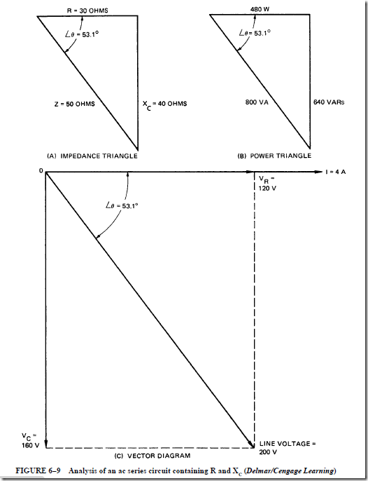
reactance are combined to obtain the impedance. The impedance triangle for this circuit is shown in Figure 6–7. The triangle consists of a base leg of resistance (30!1), an altitude leg of capacitive reactance (40 !1), and a hypotenuse of impedance (50 !1). Note that the impedance triangle for the circuit of Figure 6–6 is inverted. The reason for the position of the impedance triangle will be explained later in this problem. The hypotenuse of the impedance triangle is equal to the square root of the sum of the squares of the other two sides:

image

2. The line voltage is 200 V. This voltage causes a current in the series circuit of

image

3. The true power in the circuit is used in the resistance of the circuit because the resistance of the capacitor is negligible. The true power can be found from the formula W I2 R. The value of the lighting load is obtained by multiplying the voltage drop across the lighting load by the current. Another method of determining this load is to divide the resistance into the square of the voltage across the resistor. The actual true power can be computed by any one of the formulas given:

image

image

4. The reactive power is known as the magnetizing VARs. This quantity is the product of the current and the voltage at the capacitor terminals. This voltage is 90° out of phase with the current.

image

5. The apparent power input in volt-amperes for this circuit can be found by either of two methods:

a. Line voltage X line current volt-amperes (VA)

VI 200 X 4 800 VA

b. The input power in volt-amperes is also the result of combining the true power and the magnetizing VARs. This input power is represented in Figure 6–8 as the hypotenuse of a right triangle. The base leg in this case is the true power in watts and the altitude leg is the magnetizing VARs. The power triangle for the circuit is inverted in the same manner as the impedance triangle in Figure 6–7. The input power is the square root of the sum of the squares of the other two sides of the triangle:

image

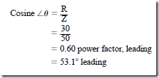
6. The input power factor for an ac series circuit is the ratio of the true power, in watts, to the input power, in volt-amperes. In other words, the input power factor is the ratio of the power leg of the power triangle to the hypotenuse. Thus, the power factor is the cosine of the included angle ().

image

DIAGRAMS FOR THE SERIES CIRCUIT

Figure 6–9 shows the impedance triangle, the power triangle, and the vector diagram for this series circuit. In Figure 6–9C, the voltage across the capacitor is drawn downward from point 0 at a 90° angle with the current vector. This position of the capacitor voltage (V ) indicates that the current leads the voltage by 90 electrical degrees.

Because the impedance triangle is drawn in an inverted position, Figure 6–9A is identical to the triangle of voltages that forms a part of the vector diagram. The capacitive reactance, in ohms, is drawn in a downward direction so that it can be compared to the voltage drop across the capacitor. This drop is shown in a similar direction in the vector diagram. The angle () is in the same position in both the impedance triangle and in the triangle of voltages in the vector diagram.

The power triangle is also drawn in an inverted position. It is similar to the other diagrams. Because the capacitor produces magnetizing VARs, the VARs are shown in a downward direction. Thus, the phase angle () is in the same position for all three diagrams. This means that the line current leads the line voltage.

The student should recognize that the formulas and triangles describing an RL circuit are the same as those describing an RC circuit. However, the VC vector is 180° out of phase

with the V vector.

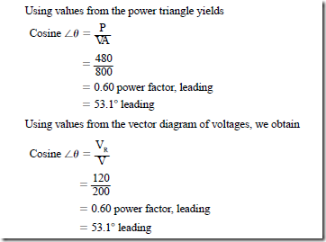
The power factor of a circuit containing resistance and capacitive reactance can be obtained using the values from any one of the three triangles given in Figure 6–9.

Using values from the impedance triangle, we obtain

image

image

image

The power factor angle (()) for this circuit is 53.1° leading. This means that the line current leads the line voltage by 53.1°.

PROBLEM 2

Statement of the Problem

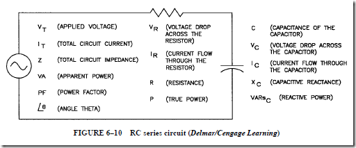
In the circuit shown in Figure 6–10, a resistor and a capacitor are connected in series. The circuit is connected to a 240-V, 60-Hz line. An ammeter measures a total current of 18.75 A, and a wattmeter indicates a true power of 3375 W. Use the formulas

image

shown in the Resistive Capacitive (Series) section of Appendix 15 to find the following values:

1. Volt-amperes, apparent power (VA)

2. Volt-amperes-reactive, reactive power (VARs)

3.Capacitive reactance (XC )

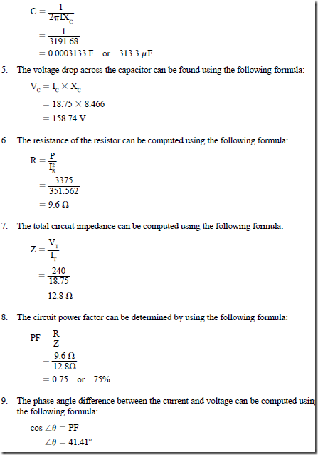
4. Capacitance (C)

5.Voltage drop across the capacitor (VC )

6.Resistance of the resistor (VR )

7. Total circuit impedance (Z)

8. Power factor (PF)

9. Angle theta, which indicates the angle at which the voltage and current are out of phase with each other (*0)

Solution

1. Because the applied voltage and total current are known, the apparent power can be computed using the following formula:

image

2. Now that both the apparent power and the true power are known, the reactive power (VARs) can be computed using the following formula:

image

3. In a series circuit, the current flow must be the same at any point in a circuit. Because the current flow and reactive power are both known, the capacitive reactance can now be computed using the following formula:

image

4. The capacitance of the capacitor can be computed using the following formula:

image

• Charging a capacitor

1. An opposition voltage builds up across the capacitor plates.

2. The charging current has a maximum value when the capacitor is uncharged.

3. The current decreases to zero as the capacitor voltage builds up to equal the source voltage.

4. The current remains at zero amperes while the source voltage equals the opposi- tion voltage of the capacitor.

• Reactance

1. The opposition voltage that develops as a capacitor charges is really a counter- voltage because it opposes the line voltage and limits the current.

2. The current-limiting effect of this countervoltage (capacitance) in an ac circuit is expressed in a unit called capacitive reactance and is measured in ohms


image

3.The value of X in ohms is inversely proportional to the capacitance in farads and the frequency of the impressed ac voltage.

• Ohm’s law for determining the current, in amperes, in an ac circuit containing capacitance is

image

• Lead/lag currents

1. Current in a pure resistor is in phase with the voltage.

2. Current in a pure inductive reactance lags the impressed voltage by 90 electrical degrees.

3. Current in a circuit with pure capacitive reactance leads the impressed voltage by 90 electrical degrees.

• Angle of phase defect

1. The phase angle between the capacitor voltage and current is slightly less than 90°.

2. In some capacitors having mica dielectrics, the angle of phase defect is as small as three or four minutes.

3. Capacitors having other types of dielectrics may have angles of phase defect greater than one degree, causing high power loss.

4. If the angle of phase defect is too large, the internal temperature of the capacitor may increase and shorten the useful life of the dielectric.

• The power factor of a capacitor relates the power losses of a capacitor to its volt-ampere rating.

1. The power factor is the ratio of the power loss to the volt-ampere rating when the capacitor is operated at the rated voltage and frequency.

2. The power factor is usually 0.01 (1%) or less for power factor correction capacitors.

• The term Q describes capacitor losses and is expressed as

imagewhere R is the equivalent resistance that includes the effects of dielectric losses and resistive losses within the capacitor.

• Q is a relatively large number and is easier to use than the small values of the power factors for capacitors.

• The dc working voltage of a capacitor should be high enough to withstand the maxi- mum or peak voltage of an ac circuit:

image

• A capacitor should be used only for the type of service for which it is designed.

• The power in a capacitor, in watts, at any instant is equal to the product of the voltage and current values at the same instant.

• The true power or net power taken by the capacitor at the end of one complete cycle, or at the end of any number of complete cycles, is zero.

• Magnetizing VARs are present in a pure inductive circuit where the current lags the applied voltage by a value up to 90 electrical degrees.

• Magnetizing VARs are present in a pure capacitive circuit where the current leads the applied voltage by a value up to 90 electrical degrees.

• Magnetizing VARs are represented by the product of the applied voltage and the current. (This value does not represent a true power loss.)

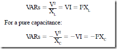
• For a pure inductance:

image

(The minus sign means that the VARs for a capacitor are opposite to those for an inductance.)

• Coils consume magnetizing VARs, and capacitors supply magnetizing VARs.

• A circuit is in resonance when

1. the circuit is viewed from the input terminals and it appears to be pure resistance.

2. there is a balance between the magnetizing VAR supply and the demand.

3. the inductive elements of certain circuits receive a value of magnetizing VARs equal to that produced by the capacitive elements.

• The conservation of energy principle states that the total power supplied to a circuit is equal to the sum of the values of power consumed in each of the individual circuit components.

• In an ac power system, an adequate supply of watts and magnetizing VARs must be available if the system is to perform as expected.

• Inductive load equipment, such as fluorescent light ballasts, power distribution lines, and induction motors, all require capacitors to ensure an adequate supply of magnetiz- ing VARs.

Achievement Review

1. What is capacitive reactance?

2. Three capacitors are connected in parallel across a 230-V, 60-Hz supply. These capacitors have values of 10 f.LF, 30 f.LF, and 60 f.LF.

a. A single capacitor can replace the three capacitors. What value of capacitance is required to do this?

b. Determine the total current taken by the three capacitors.

c. What is the current in the 10-f.LF capacitor?

3. The three capacitors in question 2 are reconnected in series across the same ac supply.

image


b. Assuming that this same capacitor is connected across a 240-V, 25-Hz source, determine

(1) the capacitive reactance, in ohms.

(2) the current, in amperes.

c. Give reasons for any differences in the capacitive reactance and the current in parts (a) and (b) of this problem.

5. Explain what is meant by the term angle of phase defect.

6. A capacitor has an angle of phase defect of 1.2°.

a. What is the actual angle by which the current leads the impressed voltage for this capacitor?

b. What is its power factor?

7. A noninductive load with a resistance of 30 !1 is connected in series with a capacitor. The capacitor has a capacitive reactance of 25 !1 and negligible resis- tance. The series circuit is energized from a 210-V, 60-Hz source. Determine

a. the impedance of the series circuit.

b. the current, in amperes.

c. the loss in volts across the noninductive resistance load.

d. the loss in volts across the capacitor.

8. For question 7, determine

a. the power in watts expended in the series circuit.

b. the volt-amperes-reactive component for the series circuit, in VARs.

c. the apparent power, in volt-amperes.

d. the circuit power factor.

e. the power factor angle for this circuit.

9. For the series circuit in question 7, draw the following diagrams using con- venient scales:

a. An impedance triangle

b. A power triangle

c. A vector diagram

10. What is the rating, in microfarads, of the capacitor used in the series circuit in question 7?

11. An experimental series circuit consists of a noninductive variable resistor con- nected in series with a 1-f.LF capacitor of negligible resistance. The variable resis- tor has a maximum resistance of 5000 !1. This series circuit is connected across a 50-V, 60-Hz source.

a. If the current is to lead the line voltage by a phase angle of 45°, what is the resistance in ohms that must be inserted in the series circuit by adjusting the variable resistor?

b. What is the current in this series circuit?

c. What is the power factor of this circuit?

d. What is the power expended in the circuit?

12. In question 11, determine

a. the loss in volts across the variable resistor.

b. the loss in volts across the capacitor.

c. the volt-ampere reactive component (VARs) for the capacitor.

d. the apparent power for the entire series circuit.

13. For the circuit in question 11, draw the impedance triangle and the vector dia- gram, using convenient scales.

14. A paper capacitor can be used in ac and dc circuits. It has a dc working voltage of 500 V. Can this capacitor be connected directly across a 440-V, 60-Hz source?

15. A capacitor is connected across a 120-V, 60-Hz supply. An ammeter indicates 5 A and a wattmeter indicates 10 W. Determine

a. the resistance of the capacitor.

b. the power factor.

c. the phase angle to the nearest tenth of a degree.

d. the angle of phase defect to the nearest tenth of a degree.

image

image


Capacitors in Alternating-Current Circuits : Capacitive reactance , Leading current , Angle of phase defect , Voltage rating of a capacitor and Power in a capacitor.

Capacitors in Alternating-Current Circuits

CAPACITIVE REACTANCE

A capacitor connected to an ac supply repeatedly charges and discharges as the ac voltage changes direction. The charging current also alternates in direction as the capacitor charges and discharges.

In the circuit in Figure 6–1, a 26.52-f.LF capacitor is connected across a 100-V, 60-Hz source. The ammeter indicates a current of one ampere. The dielectric of the capacitor prevents electrons from being conducted through the capacitor. However, there is elec- tron flow to and from the plates of the capacitor as it charges and discharges in each cycle. The opposition voltage increases as the electrostatic field builds up across the plates. This voltage opposes the line voltage and limits the current. The opposition voltage that develops with a capacitor is really a countervoltage.

Inductance in an ac circuit also causes a countervoltage. The current-limiting effect of this countervoltage is measured as ohms of inductive reactance. The current-limiting effect of capacitance in an ac circuit is called capacitive reactance and is measured in ohms.

image

Current in the Capacitive Circuit

The current, in amperes, in an ac circuit containing capacitance is determined using a form of Ohm’s law. That is, capacitive reactance (X ) is substituted for resistance (R) as follows:

image

The formula for capacitive reactance shows that the value in ohms is inversely proportional to the capacitance in farads and the frequency of the impressed ac voltage. This relationship is logical because the charge on a capacitor is directly proportional to the capacitance for a given applied voltage. The pattern of this charge is an alternating current as the applied voltage alternates. If the capacitance increases for a given frequency and voltage, then the charge that flows in a given time must also increase. Thus, the current increases. If the frequency increases for a given capacitance and voltage, the same charge must flow per voltage alternation, but in a shorter time. Thus, an increase in frequency results in a larger current because current is a measure of the rate of flow of electrons.

An increase in either the frequency or the capacitance gives rise to an increase in current for a given applied voltage. It follows that an increase in the frequency or capaci- tance results in a decrease of the capacitive reactance (ohms).

LEADING CURRENT

The capacitor shown in Figure 6–1 has a capacitive reactance of 100 !1 and negligible resistance. The current in this circuit is one ampere. It was shown earlier in this text that the current in a pure resistive load is in phase with the voltage. In addition, it was shown that the current through a pure inductive reactance lags the impressed voltage by 90 electrical degrees. This unit will show that in a circuit with pure capacitive reactance, the current will lead the impressed voltage by 90 electrical degrees.

Alternating Voltage Applied to a Capacitor

A capacitor is charged when a dc voltage is applied to its terminals. The capacitor is discharged if a resistor is connected across its terminals. When an alternating voltage is applied to a capacitor, an alternating current of the same frequency repeatedly charges and discharges the capacitor. The charge in coulombs on the capacitor is proportional to the impressed voltage. As shown in Figure 6–2, the charge in coulombs is in phase with the impressed voltage (Q C X V). At zero voltage, the charge in coulombs is also zero. At the maximum positive and negative values of impressed voltage, the charge in coulombs is also at maximum.

Operation from 0° to 180°. The wave patterns for the impressed voltage and the charge are shown in Figure 6–2. The current is shown leading the line voltage by 90 electrical degrees. In the interval from 0° to 90°, the impressed voltage increases and the capacitor is charging. At 90° the capacitor voltage no longer increases. At this point, then, the cur- rent is zero. As the impressed voltage starts to decrease, the capacitor starts to discharge.

image

The electrons now flow from the plates in a direction reversed from the initial charging direction. This is shown by the current as it increases in the negative (discharging) direction. At the same time, the impressed voltage decreases to zero during the interval from 90° to 180°.

Operation from 180° to 360°. At 180°, the line voltage is zero. The charge, in coulombs, is zero and the current is at its maximum value. The capacitor now begins to charge in the opposite direction, and the impressed voltage starts to rise toward its negative maximum value. The current is in the same direction as the impressed voltage in the range from 180° to 270°. The current decreases in magnitude as the rate of change of voltage decreases. At 270 electrical degrees, the capacitor voltage no longer increases. Therefore, the current is zero at 270°. Between 270° and 360°, the voltage again decreases to zero. As the negative charge is removed from the capacitor, the capacitor current increases in a positive direction. The capacitor voltage decreases to zero and the current rises in the positive direction to its maximum value at 360°. The capacitor is completely discharged at 360°.

ANGLE OF PHASE DEFECT

For circuits containing inductance coils, both the resistance and the inductive reactance must be considered. For circuits containing capacitors operating at commercial power frequencies, the resistance losses are usually assumed to be negligible. At such frequencies, the capacitor current leads the capacitor voltage by 90 electrical degrees.

Under actual operating conditions, the angle by which the capacitor current leads the voltage is slightly less than 90°. The angle of phase defect is the angle by which the phase angle between the capacitor voltage and current is less than 90°. The angles of phase defect for some capacitors having mica dielectrics are as small as three or four minutes. Capacitors having other types of dielectrics may have angles of phase defect greater than one degree. If the angle of phase defect becomes too large, the capacitor has a relatively

high power loss. Such a loss causes an increase in the internal temperature of the capacitor. This temperature rise can shorten the useful life of the dielectric.

Power Factor of a Capacitor

The power factor of a capacitor relates the power losses of a capacitor to its volt-ampere rating. The power factor is the ratio of the power loss to the volt-ampere rating when the capacitor is operated at the rated voltage and frequency. The power factor is usually 0.01 [one percent (1%)] or less for power factor correction capacitors.

Q of a Capacitor

The term Q is used to describe capacitor losses. Q is given by the following expression:

imageIn this expression, the term RC is the equivalent resistance that must be placed in series with a perfect capacitor to produce a loss in watts that is the same as the loss in the actual imperfect capacitor. This resistance includes the effects of dielectric losses and resistive losses. Capacitor Q may also be defined as follows:

image

As Q is a relatively large number, it is often simpler to use than the very small power factor values of capacitors.

VOLTAGE RATING OF A CAPACITOR

Capacitors that are used in either ac or dc circuits have a rating known as the dc work- ing voltage. As an example, consider a paper capacitor made with Pyranol and enclosed in a metal container. Such a capacitor may have a rating specified as “600-V dc working voltage.” It is of interest to determine whether this capacitor can be used on a 600-V ac circuit. A previous unit showed that ac voltages are given as effective values that are always 0.707 of the maximum value. The voltage of a 600-V ac circuit reaches a maximum instantaneous value twice in each cycle. This maximum value is

image

The dielectric of the capacitor is designed for 600 V. Because the ac voltage exceeds this value twice in each cycle, the dielectric can break down and the capacitor can be ruined. This maximum voltage has a short duration. However, the dc working voltage of a capacitor should be high enough to withstand the maximum or peak voltage of an ac circuit.

If the capacitor is not designed for ac service, it may have a short life when operated on ac, even if the applied maximum ac voltage does not exceed the dc working voltage. A capacitor operating on ac has an increase in the power losses. These greater losses may cause excessive internal operating temperatures. This and other factors result in the premature failure of dc capacitors operated on ac. It is recommended that a capacitor be used only in the type of service for which it is designed.

POWER IN A CAPACITOR

The circuit shown in Figure 6–1 has a maximum value of 141.4 V. The current leads the line voltage by 90°. Because the effective current is one ampere, the maxi- mum value of the current is 1.414 A. The power, in watts, at any instant is equal to the product of the voltage and current values at the same instant. Table 6–1 summarizes

image

the instantaneous voltage, current, and power values at 15° intervals for the circuit in Figure 6–1.

Wave Patterns for Pure Capacitance

The values in Table 6–1 are plotted against electrical time degrees to obtain the voltage, current, and power waveforms shown in Figure 6–3. Between 0° and 90°, the voltage and the current are positive. The product of the instantaneous voltage and cur- rent values in this part of the cycle will give positive power. This means that the capacitor receives energy from the supply between 0° and 90°. This energy is stored in the electro- static field of the capacitor.

In the period between 90° and 180°, the current rises to its negative maximum value. The impressed voltage is positive and decreases to zero. The product of the instantaneous negative current values and the positive voltage values from 90° to 180° gives negative power. Thus, the capacitor discharges in this period and returns its stored energy to the source.

From 180° to 270°, both the current and the impressed voltage are negative and act together. The product of these instantaneous values (with like signs) gives positive power for this part of the cycle. This means that the capacitor is charging again and storing electrical energy.

The voltage is negative from 270° to 360°. At the same time, the current rises in a positive direction. The product of a negative voltage value and a positive current value gives a negative power value. During this part of the cycle, the capacitor discharges, releasing electrical energy back into the circuit.

image

Power Waveform. Figure 6–3 shows that for the power waveform, the areas of the two positive pulses of power are equal to the areas of the two negative pulses of power. The positive power pulses represent power fed from the source to the load. The negative pulses of power represent the power returned to the source from the capacitor as it discharges. If the areas of positive power equal the areas of negative power, the net power taken by the capacitor at the end of one complete cycle, or at the end of any number of complete cycles, is zero.


Capacitors and RC Time Constants : RL time constants , Applications of capacitors , Types of capacitors and Capacitor markings.

RL TIME CONSTANTS

A discussion of time constants for RL series circuits is given here because the exponential curves and calculations involved are similar to those for RC series circuits.

Current in an RL Circuit

Any inductance coil is really a combination of inductance and resistance in series. If the coil is connected to a dc supply, the final value of current is given by Ohm’s law, I = V/R. However, the current does not rise to the Ohm’s law value instantaneously. The current increases exponentially because the inductance opposes the change in current (Figure 5–16).

RL Exponential Current Curve. The exponential curve for current in an RL circuit is shown in Figure 5–16. When the circuit is energized, the induced voltage is at its maximum value. It then decreases as the rate of increase of current becomes less. The current reaches its Ohm’s law value at the end of five time constants. At this point, the induced voltage is zero.

When the circuit is deenergized, the decay of current causes an induced voltage. This voltage attempts to maintain the current. Figure 5–17 shows the gradual decay of current as the induced voltage decreases. At the end of five time constants, the current and the induced voltage are close to zero.

The RL Time Constant

It was shown for RC circuits that one time constant is equal to the resistance in ohms times the capacitance in farads: T = RC.

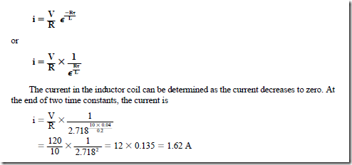
In an RL circuit, the current at the end of one time constant is 63.2% of its final value as determined by Ohm’s law. The time constant for an RL circuit is equal to the ratio of the inductance in henrys to the resistance in ohms: T = L –: R.

For example, assume that a coil has an inductance of 0.2 H and a resistance of 10 D.

One time constant is found to be

image

image

image

APPLICATIONS OF CAPACITORS

There are many practical applications for capacitors in electricity and electronics. For example, in power applications, capacitors are used to improve the power factor of distribution circuits. The starting torque of certain types of single-phase induction motors can be improved by the addition of capacitors. Capacitors are used with rectifier units to change pulsating direct current to a constant dc. Nonpulsating direct current is used with electronic components.

Capacitors have many applications in communication electronics at audio, radio, and video frequencies. Capacitors are used in special phase shift circuits to control the plate current conduction of thyratron and ignitron tubes. Capacitors are also used in electronic time-delay systems and in phototube circuits, as well as in numerous other industrial applications. Examples of typical capacitors are shown in Figure 5–18.

TYPES OF CAPACITORS

The most basic form of fixed capacitor consists of two metal plates separated by a thin dielectric material. This material may be ceramic or mica. This simple capacitor is enclosed in a plastic case. Two leads pass through the case and connect to the plates. In some capacitors, a number of plates are placed between sheets of dielectric with alternate plates connected in parallel. This arrangement increases the plate area, resulting in an increase in the capacitance. Figure 5–19 shows one type of simple capacitor. Such a capacitor is usually rated in microfarads or picofarads.

Tubular Capacitors

A second type of capacitor is shown in Figure 5–20. The capacitance rating of this tubular paper capacitor is larger than that of a mica capacitor. The capacitor consists of a strip of waxed paper placed between two strips of tinfoil or aluminum foil. The paper and foil strips are about an inch wide and 8 to 12 ft in length. The strips are rolled and placed in

image

a small plastic or metal cylinder. The resulting capacitor is physically small, but has a large plate area and a large value of capacitance.

The tinfoil or aluminum foil plates are often separated by a thin film of paper treated with an oil, or by a film of plastic. The paper capacitor (Figure 5–21) is enclosed in a flat case or an oil-filled can.

Ceramic Capacitors

Ceramic capacitors consist of a ceramic dielectric and silver plates. The dielectric is a ceramic compound such as barium titanate or titanium dioxide. The dielectric is usually in the form of a disc. The silver plates are secured to each side of this thin ceramic disc.

image

Ceramic capacitors have capacitance ratings as high as 2.0 p,F. This rating is large considering the relatively small size of the capacitor.

Electrolytic Capacitors

Another type of capacitor is used for direct-current applications generally. An electrolytic capacitor is shown in Figure 5–22. The positive plate is made from aluminum foil. This plate is immersed in an electrolyte consisting of a borax solution. The electrolyte serves as the negative plate of the capacitor. A second piece of aluminum foil is placed between the electrolyte and the negative terminal of the capacitor. When the capacitor is energized from a dc source, an insulating film of oxide develops on the positive aluminum foil. This film forms a very thin dielectric. The extremely thin dielectric means that the electrolytic capacitor has a very high capacitance rating for its physical size.

A more popular type of capacitor is the dry electrolytic capacitor. The electrolyte in this type of capacitor is gauze saturated with a borax solution. This dry capacitor has the advantage that there is no liquid electrolyte to leak from the case.

Connecting Electrolytic Capacitors. When connecting an electrolytic capacitor into a dc circuit, the positive aluminum plate must be connected to the positive side of the circuit. If this type of capacitor is installed with its connections reversed, the dielectric will be punctured. With the wet electrolytic capacitor, the dielectric will repair itself if the capacitor is reconnected properly. The dry capacitor, however, is permanently damaged if the connections are reversed.

AC Electrolytic Capacitor. The electrolytic capacitor described in the previous para- graphs cannot be used in an alternating-current circuit. Because the voltage is continually changing direction, the dielectric of the capacitor will be punctured repeatedly. However, a form of the electrolytic capacitor known as a nonpolarized electrolytic capacitor can be used in alternating-current circuits. This capacitor is really two wet, self-healing electro- lytic capacitors assembled in a series back-to-back arrangement. The like plates of these

image

capacitors are connected together. When an ac voltage is applied to the two outside terminals, one capacitor will be connected properly. At the same time, the dielectric of the second capacitor will be punctured. Then, in the other half-cycle, this process is reversed. Thus, there is always one capacitor connected properly, regardless of the direction of the ac voltage.

Air Capacitors

A common form of the variable-air capacitor is shown in Figure 5–23. One group of plates is mounted so they are movable with respect to a group of fixed plates. The movable plates are called the rotor and the fixed plates are called the stator. This type of capacitor is ideal for tuning radio receivers because the capacitance can be varied at low values, in the order of picofarads. The typical capacitance range of a variable air capacitor is between 500 pF and zero.

The trimmer capacitor (Figure 5–24) has two metal plates with an air dielectric. The spacing between the plates can be changed by means of an insulated setscrew. As the set- screw is tightened, the spacing is decreased. As a result, the capacitance is increased.

Capacitor Symbols

The symbol for any type of fixed capacitor is shown in Figure 5–25A. In schematic diagrams, the curved portion of the symbol is connected to ground, or to the low or negative voltage side of the circuit. The symbols for variable capacitors are given in Figure 5–25B.

CAPACITOR MARKINGS

Different types of capacitors are marked in different ways. Capacitance and voltage values are usually written directly on large ac oil-filled paper capacitors. The same is true for most electrolytic and small nonpolarized capacitors. Other types of capacitors, how- ever, depend on color codes or code numbers and letters to indicate the capacitance value,

image

tolerance, and voltage rating. Although color coding for capacitors has been abandoned in favor of direct marking by most manufacturers, it is still used by some. Also, many older capacitors with color codes are still in use. For this reason, this text will discuss color coding for several different types of capacitors.

Unfortunately, there is no actual set standard used by all manufacturers. The color codes presented are probably the most common. An identification chart for “postage stamp” mica capacitors and tubular paper or tubular mica capacitors is shown in Figure 5–26. It should be noted that most “postage stamp” mica capacitors use a five-dot color code. There are six-dot color codes, however. When a six-dot color code is used, the third color dot rep- resents a third digit and the rest of the code is the same. The capacitance values given are in picofarads. Although these markings are typical, there is no actual standard, and it may be necessary to use manufacture’s literature to determine the true values. A second method for

image

color coding mica capacitors is called the Electronic Industries Association (EIA) standard, or the Joint Army-Navy (JAN) standard. The JAN standard is used for electronic components intended for military use. When the EIA standard is employed, the first dot will be colored white. In some instances, the first dot may be colored silver instead of white. This indicates that the capacitor’s dielectric is paper instead of mica. When the JAN standard is used, the first dot will be colored black. The second and third dots represent digits, the fourth dot is the multiplier, the fifth dot is the tolerance, and the sixth dot indicates classes A through E of temperature and leakage coefficients.

Temperature Coefficients

The temperature coefficient indicates the amount of capacitance change with tem- perature. Temperature coefficients are listed in parts per million (ppm) per degree Celsius (°C). A positive temperature coefficient indicates that the capacitor will increase its capacitance with an increase in temperature. A negative temperature coefficient indicates that the capacitance will decrease with an increase in temperature.

Ceramic Capacitors

Another capacitor that often uses color codes is the ceramic capacitor (Figure 5–27). This capacitor will generally have one band that is wider than the others. The wide band indicates the temperature coefficient, and the other bands are first and second digits, multiplier, and tolerance.

Dipped Tantalum Capacitors

A dipped tantalum capacitor is shown in Figure 5–28. This capacitor has the general shape of a match head but is somewhat larger in size. Color bands and dots determine the value, tolerance, and voltage. The capacitance value is given in picofarads.

Film Capacitors

Not all capacitors use color codes to indicate values. Some capacitors use numbers and letters. A film-type capacitor is shown in Figure 5–29. This capacitor is marked “105K.” The value can be read as follows:

1. The first two numbers indicate the first two digits of the value.

2. The third number is the multiplier. Add the number of zeros to the first two numbers indicated by the multiplier. In this example, add five zeros to 10. The value is given in picofarads. This capacitor has a value of 1,000,000 pF, or 1 p,F.

3. The K symbol indicates the tolerance. In this example, K indicates a tolerance of ±10%.

SUMMARY

• The elementary capacitor consists of two metal plates separated from each other by a dielectric (insulating material).

image

1. During the charge process, electrons flow from the negative side of the source to one plate and from the second plate back to the source.

2. There is almost no flow of electrons through the dielectric material.

3. The movement of electrons continues until the potential difference across the two metal plates is equal to the source voltage. At this point, the capacitor is said to be fully charged.

4. The charges on the plates of the capacitor act on the electrons of the atoms in the dielectric and cause the orbits of these electrons to be distorted.

5. An electrostatic field created by the charged plates maintains the distortion of the electron orbits in the dielectric atoms. This electrostatic field stores electrical energy.

6. The distortion dissipates once the capacitor is discharged. The electron orbits of the atoms of the dielectric return to their normal pattern.

image

• Capacitance is the property of a circuit, or circuit component, that allows it to store electrical energy in electrostatic form.

1. Capacitance is measured in farads. A capacitor has a capacitance of one farad when a change of one volt across its plates results in a charge movement of one coulomb:

image

image

2. The capacitance of a capacitor can be increased by

a. increasing the plate area to increase the area of dielectric under stress.

b. moving the metal plates closer together to decrease the thickness of the dielectric, resulting in a greater stress.

c. using a dielectric with a higher dielectric constant.

(1) The dielectric constant of an insulating material measures the effective- ness of the material when used as the dielectric of a capacitor. This gives a value indicating the degree of distortion of the electron orbits in the dielectric for a given applied voltage.

(2) The dielectric constants of all other materials are measured against air, which is assumed to be one.

• Circuit components other than capacitors may create a capacitance effect.

1. When two wires of a circuit are separated by air, they will act as a capacitor.

2. Adjacent turns of a coil winding, which are separated only by the insulation of the wire, will have some capacitance effect.

• The charge on the plates of a capacitor for a given applied voltage is directly proportional to the capacitance of the capacitor:

image

• Dielectric materials are given a dielectric strength rating:

1. This rating is stated as either “volts per centimeter” or “volts per mil” of dielectric thickness required to break down the dielectric.

2. It is not the same as the dielectric constant.

• The formulas used to determine the capacitance of a two-plate capacitor are

Measurements in inches:

image

Measurements in centimeters:

image

• The total capacitance when capacitors are connected in parallel is given by

imageWhen capacitors are connected in parallel, the effect is the same as increasing the number of plates or the area of the plates.

• The total capacitance when capacitors are connected in series is given by

image

When capacitors are connected in series, the effect is equivalent to increasing the thick- ness of the dielectric of one capacitor, resulting in less capacitance.

• The formulas for total capacitance can be used only when all of the values are in the same unit of capacitance measurement, either microfarads or picofarads.

• The amount of energy stored in a capacitor is measured in joules or watt-seconds:

image

• The amount of charge on the plates of a capacitor is a function of the current and time.

1. As the value of the current increases, less time is required to charge the capacitor fully.

2. The time required for a given voltage to build up across the capacitor can be con- trolled by increasing or decreasing the charging current

image

where T is the Greek letter tau, the letter symbol for a time constant expressed in seconds.

• One time constant is the time, in seconds, required for a completely discharged capacitor to charge to 63% of the source voltage.

1. For all practical purposes, it is assumed that the capacitor is fully charged at the end of five time constants.

2. For all practical purposes, it is assumed that a fully charged capacitor will be completely discharged at the end of five time constants of discharge.

• The relationship of the current to the supply voltage for a capacitor being charged can be found at any instant:

image

• When connecting an electrolytic capacitor, the plates must be properly connected.

1. For the wet electrolytic capacitor, the dielectric will repair itself after being punctured as a result of reversed connections.

2. If the connections of the dry electrolytic capacitor are reversed, the dielectric is permanently damaged.

3. The electrolytic capacitor cannot be used in an alternating-current circuit. How- ever, a nonpolarized electrolytic capacitor can be used in ac circuits.

Achievement Review

1. List three factors that affect the capacitance of a capacitor.

2. Define the basic unit of measurement of capacitance.

3. A capacitor takes a charge of 0.05 coulomb (C) when connected across a 250-V source. Determine the capacitance of the capacitor in microfarads.

4. Explain what is meant by the term dielectric constant.

5. A paper capacitor consists of two aluminum foil plates, each 10 ft long and 1.5 in. wide. The waxed paper separating the two plates has a thickness of 0.04 in. The dielectric constant is assumed to be 2. Determine the capacitance of the capacitor, using both formulas:

image

6. Three capacitors have ratings of 20 p,F, 60 p,F, and 30 p,F, respectively. These capacitors are connected in parallel across a 220-V dc source. Determine

a. the total capacitance of the three capacitors connected in parallel.

b. the total charge, in coulombs, taken by the three capacitors in parallel when connected across a 220-V dc source.

7. The three capacitors in question 6 are connected in series across a 220-V dc source. Determine

a. the total capacitance of the three capacitors connected in series.

b. the total charge, in coulombs, taken by the three capacitors in series when connected across a 220-V dc source.

8. Explain what is meant by the term dielectric strength rating.

9. List five practical applications for capacitors.

10. Determine the energy, in watt-seconds, stored in a 100-p,F capacitor when connected across a 400-V dc source.

11. A 100-p,F capacitor is connected in series with a 500-V dc voltmeter across a 400-V dc supply. The voltmeter has a resistance of 1000 D/V.

a. Determine the time, in seconds, represented by one time constant for this RC series circuit.

b. Determine the voltage across the capacitor plates at the end of one time constant when the capacitor is on charge.

12. Using the circuit given in question 11, determine

a. the voltage across the capacitor plates at the end of two time constants, when the capacitor is charging.

b. the voltage across the capacitor plates, at the end of five time constants, when the capacitor is charging.

13. Using the circuit given in question 11, determine the voltage across the plates of the capacitor, at the end of one time constant, when the capacitor is discharging.

14. At the end of one time constant, what is the charging current in amperes for the RC series circuit given in question 11?

15. Determine the time constant, in seconds, for an inductor coil with an inductance of 0.5 H and a resistance of 10 D.

16. If the inductor coil in question 15 is connected across a 120-V source, determine

a. the initial current, in amperes, at the instant the circuit is energized.

b. the current, in amperes, at the end of one time constant after the circuit is energized.

c. the current, in amperes, at the end of two time constants after the circuit is energized.

17. When the inductor coil in question 16 is deenergized, determine the value of the decaying current in amperes

a. at the end of two time constants.

b. at the end of five time constants.

18. a. Explain the difference between a wet and a dry electrolytic capacitor.

b. Where are electrolytic capacitors used?

19. Name four other types of capacitors, in addition to the electrolytic capacitor, that were described in this unit. Briefly describe the material used for the plates and the dielectrics of each type.

20. In schematic wiring diagrams, the curved portion of the symbol for a fixed capaci- tor should be connected in a particular manner. Explain what is meant by this statement.

image


Capacitors and RC Time Constants : RL time constants , Applications of capacitors , Types of capacitors and Capacitor markings.

RL TIME CONSTANTS

A discussion of time constants for RL series circuits is given here because the exponential curves and calculations involved are similar to those for RC series circuits.

Current in an RL Circuit

Any inductance coil is really a combination of inductance and resistance in series. If the coil is connected to a dc supply, the final value of current is given by Ohm’s law, I = V/R. However, the current does not rise to the Ohm’s law value instantaneously. The current increases exponentially because the inductance opposes the change in current (Figure 5–16).

RL Exponential Current Curve. The exponential curve for current in an RL circuit is shown in Figure 5–16. When the circuit is energized, the induced voltage is at its maximum value. It then decreases as the rate of increase of current becomes less. The current reaches its Ohm’s law value at the end of five time constants. At this point, the induced voltage is zero.

When the circuit is deenergized, the decay of current causes an induced voltage. This voltage attempts to maintain the current. Figure 5–17 shows the gradual decay of current as the induced voltage decreases. At the end of five time constants, the current and the induced voltage are close to zero.

The RL Time Constant

It was shown for RC circuits that one time constant is equal to the resistance in ohms times the capacitance in farads: T = RC.

In an RL circuit, the current at the end of one time constant is 63.2% of its final value as determined by Ohm’s law. The time constant for an RL circuit is equal to the ratio of the inductance in henrys to the resistance in ohms: T = L –: R.

For example, assume that a coil has an inductance of 0.2 H and a resistance of 10 D.

One time constant is found to be

image

image

image

APPLICATIONS OF CAPACITORS

There are many practical applications for capacitors in electricity and electronics. For example, in power applications, capacitors are used to improve the power factor of distribution circuits. The starting torque of certain types of single-phase induction motors can be improved by the addition of capacitors. Capacitors are used with rectifier units to change pulsating direct current to a constant dc. Nonpulsating direct current is used with electronic components.

Capacitors have many applications in communication electronics at audio, radio, and video frequencies. Capacitors are used in special phase shift circuits to control the plate current conduction of thyratron and ignitron tubes. Capacitors are also used in electronic time-delay systems and in phototube circuits, as well as in numerous other industrial applications. Examples of typical capacitors are shown in Figure 5–18.

TYPES OF CAPACITORS

The most basic form of fixed capacitor consists of two metal plates separated by a thin dielectric material. This material may be ceramic or mica. This simple capacitor is enclosed in a plastic case. Two leads pass through the case and connect to the plates. In some capacitors, a number of plates are placed between sheets of dielectric with alternate plates connected in parallel. This arrangement increases the plate area, resulting in an increase in the capacitance. Figure 5–19 shows one type of simple capacitor. Such a capacitor is usually rated in microfarads or picofarads.

Tubular Capacitors

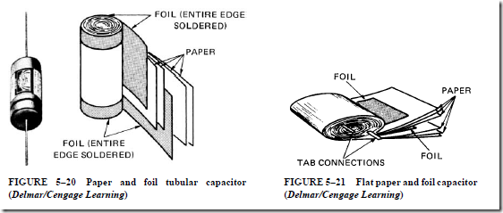
A second type of capacitor is shown in Figure 5–20. The capacitance rating of this tubular paper capacitor is larger than that of a mica capacitor. The capacitor consists of a strip of waxed paper placed between two strips of tinfoil or aluminum foil. The paper and foil strips are about an inch wide and 8 to 12 ft in length. The strips are rolled and placed in

image

a small plastic or metal cylinder. The resulting capacitor is physically small, but has a large plate area and a large value of capacitance.

The tinfoil or aluminum foil plates are often separated by a thin film of paper treated with an oil, or by a film of plastic. The paper capacitor (Figure 5–21) is enclosed in a flat case or an oil-filled can.

Ceramic Capacitors

Ceramic capacitors consist of a ceramic dielectric and silver plates. The dielectric is a ceramic compound such as barium titanate or titanium dioxide. The dielectric is usually in the form of a disc. The silver plates are secured to each side of this thin ceramic disc.
image

Ceramic capacitors have capacitance ratings as high as 2.0 p,F. This rating is large considering the relatively small size of the capacitor.

Electrolytic Capacitors

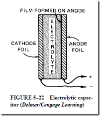
Another type of capacitor is used for direct-current applications generally. An electrolytic capacitor is shown in Figure 5–22. The positive plate is made from aluminum foil. This plate is immersed in an electrolyte consisting of a borax solution. The electrolyte serves as the negative plate of the capacitor. A second piece of aluminum foil is placed between the electrolyte and the negative terminal of the capacitor. When the capacitor is energized from a dc source, an insulating film of oxide develops on the positive aluminum foil. This film forms a very thin dielectric. The extremely thin dielectric means that the electrolytic capacitor has a very high capacitance rating for its physical size.

A more popular type of capacitor is the dry electrolytic capacitor. The electrolyte in this type of capacitor is gauze saturated with a borax solution. This dry capacitor has the advantage that there is no liquid electrolyte to leak from the case.

Connecting Electrolytic Capacitors. When connecting an electrolytic capacitor into a dc circuit, the positive aluminum plate must be connected to the positive side of the circuit. If this type of capacitor is installed with its connections reversed, the dielectric will be punctured. With the wet electrolytic capacitor, the dielectric will repair itself if the capacitor is reconnected properly. The dry capacitor, however, is permanently damaged if the connections are reversed.

AC Electrolytic Capacitor. The electrolytic capacitor described in the previous para- graphs cannot be used in an alternating-current circuit. Because the voltage is continually changing direction, the dielectric of the capacitor will be punctured repeatedly. However, a form of the electrolytic capacitor known as a nonpolarized electrolytic capacitor can be used in alternating-current circuits. This capacitor is really two wet, self-healing electro- lytic capacitors assembled in a series back-to-back arrangement. The like plates of these
image

capacitors are connected together. When an ac voltage is applied to the two outside terminals, one capacitor will be connected properly. At the same time, the dielectric of the second capacitor will be punctured. Then, in the other half-cycle, this process is reversed. Thus, there is always one capacitor connected properly, regardless of the direction of the ac voltage.

Air Capacitors

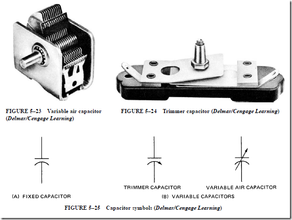
A common form of the variable-air capacitor is shown in Figure 5–23. One group of plates is mounted so they are movable with respect to a group of fixed plates. The movable plates are called the rotor and the fixed plates are called the stator. This type of capacitor is ideal for tuning radio receivers because the capacitance can be varied at low values, in the order of picofarads. The typical capacitance range of a variable air capacitor is between 500 pF and zero.

The trimmer capacitor (Figure 5–24) has two metal plates with an air dielectric. The spacing between the plates can be changed by means of an insulated setscrew. As the set- screw is tightened, the spacing is decreased. As a result, the capacitance is increased.

Capacitor Symbols

The symbol for any type of fixed capacitor is shown in Figure 5–25A. In schematic diagrams, the curved portion of the symbol is connected to ground, or to the low or negative voltage side of the circuit. The symbols for variable capacitors are given in Figure 5–25B.

CAPACITOR MARKINGS

Different types of capacitors are marked in different ways. Capacitance and voltage values are usually written directly on large ac oil-filled paper capacitors. The same is true for most electrolytic and small nonpolarized capacitors. Other types of capacitors, how- ever, depend on color codes or code numbers and letters to indicate the capacitance value,
image

tolerance, and voltage rating. Although color coding for capacitors has been abandoned in favor of direct marking by most manufacturers, it is still used by some. Also, many older capacitors with color codes are still in use. For this reason, this text will discuss color coding for several different types of capacitors.

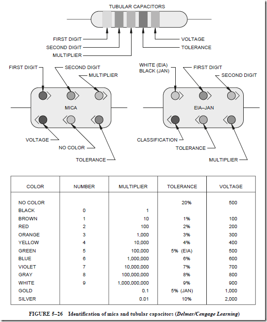
Unfortunately, there is no actual set standard used by all manufacturers. The color codes presented are probably the most common. An identification chart for “postage stamp” mica capacitors and tubular paper or tubular mica capacitors is shown in Figure 5–26. It should be noted that most “postage stamp” mica capacitors use a five-dot color code. There are six-dot color codes, however. When a six-dot color code is used, the third color dot rep- resents a third digit and the rest of the code is the same. The capacitance values given are in picofarads. Although these markings are typical, there is no actual standard, and it may be necessary to use manufacture’s literature to determine the true values. A second method for
image

color coding mica capacitors is called the Electronic Industries Association (EIA) standard, or the Joint Army-Navy (JAN) standard. The JAN standard is used for electronic components intended for military use. When the EIA standard is employed, the first dot will be colored white. In some instances, the first dot may be colored silver instead of white. This indicates that the capacitor’s dielectric is paper instead of mica. When the JAN standard is used, the first dot will be colored black. The second and third dots represent digits, the fourth dot is the multiplier, the fifth dot is the tolerance, and the sixth dot indicates classes A through E of temperature and leakage coefficients.

Temperature Coefficients

The temperature coefficient indicates the amount of capacitance change with tem- perature. Temperature coefficients are listed in parts per million (ppm) per degree Celsius (°C). A positive temperature coefficient indicates that the capacitor will increase its capacitance with an increase in temperature. A negative temperature coefficient indicates that the capacitance will decrease with an increase in temperature.

Ceramic Capacitors

Another capacitor that often uses color codes is the ceramic capacitor (Figure 5–27). This capacitor will generally have one band that is wider than the others. The wide band indicates the temperature coefficient, and the other bands are first and second digits, multiplier, and tolerance.

Dipped Tantalum Capacitors

A dipped tantalum capacitor is shown in Figure 5–28. This capacitor has the general shape of a match head but is somewhat larger in size. Color bands and dots determine the value, tolerance, and voltage. The capacitance value is given in picofarads.

Film Capacitors

Not all capacitors use color codes to indicate values. Some capacitors use numbers and letters. A film-type capacitor is shown in Figure 5–29. This capacitor is marked “105K.” The value can be read as follows:

1. The first two numbers indicate the first two digits of the value.

2. The third number is the multiplier. Add the number of zeros to the first two numbers indicated by the multiplier. In this example, add five zeros to 10. The value is given in picofarads. This capacitor has a value of 1,000,000 pF, or 1 p,F.

3. The K symbol indicates the tolerance. In this example, K indicates a tolerance of ±10%.

SUMMARY

• The elementary capacitor consists of two metal plates separated from each other by a dielectric (insulating material).
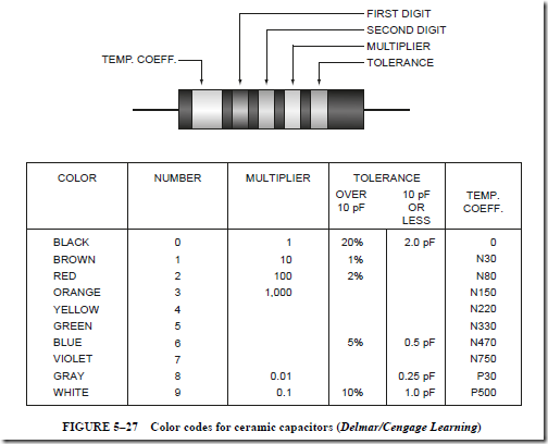
image

1. During the charge process, electrons flow from the negative side of the source to one plate and from the second plate back to the source.

2. There is almost no flow of electrons through the dielectric material.

3. The movement of electrons continues until the potential difference across the two metal plates is equal to the source voltage. At this point, the capacitor is said to be fully charged.

4. The charges on the plates of the capacitor act on the electrons of the atoms in the dielectric and cause the orbits of these electrons to be distorted.

5. An electrostatic field created by the charged plates maintains the distortion of the electron orbits in the dielectric atoms. This electrostatic field stores electrical energy.

6. The distortion dissipates once the capacitor is discharged. The electron orbits of the atoms of the dielectric return to their normal pattern.
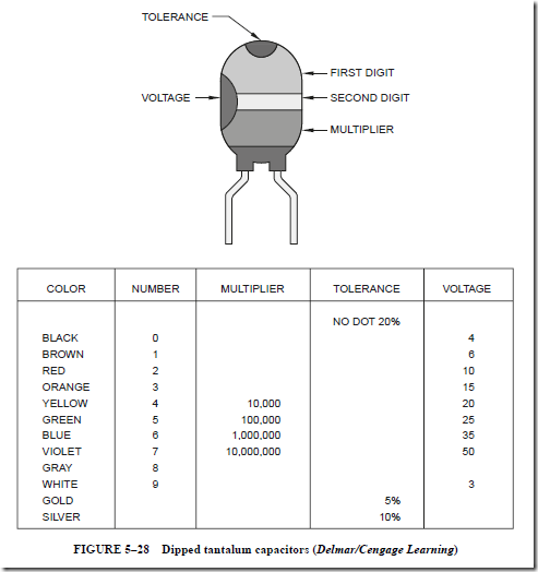
image

• Capacitance is the property of a circuit, or circuit component, that allows it to store electrical energy in electrostatic form.

1. Capacitance is measured in farads. A capacitor has a capacitance of one farad when a change of one volt across its plates results in a charge movement of one coulomb:

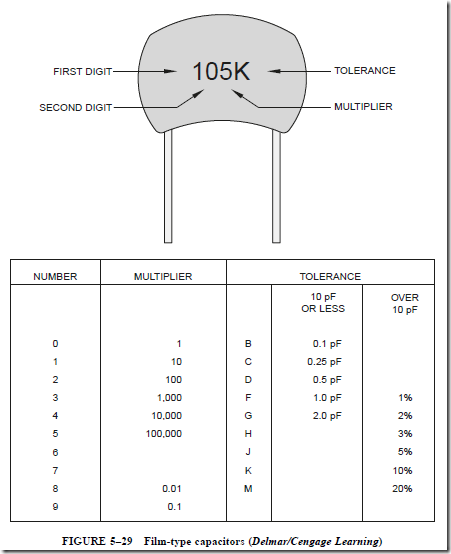
image

image

2. The capacitance of a capacitor can be increased by

a. increasing the plate area to increase the area of dielectric under stress.

b. moving the metal plates closer together to decrease the thickness of the dielectric, resulting in a greater stress.

c. using a dielectric with a higher dielectric constant.

(1) The dielectric constant of an insulating material measures the effective- ness of the material when used as the dielectric of a capacitor. This gives a value indicating the degree of distortion of the electron orbits in the dielectric for a given applied voltage.

(2) The dielectric constants of all other materials are measured against air, which is assumed to be one.

• Circuit components other than capacitors may create a capacitance effect.

1. When two wires of a circuit are separated by air, they will act as a capacitor.

2. Adjacent turns of a coil winding, which are separated only by the insulation of the wire, will have some capacitance effect.

• The charge on the plates of a capacitor for a given applied voltage is directly proportional to the capacitance of the capacitor:

image

• Dielectric materials are given a dielectric strength rating:

1. This rating is stated as either “volts per centimeter” or “volts per mil” of dielectric thickness required to break down the dielectric.

2. It is not the same as the dielectric constant.

• The formulas used to determine the capacitance of a two-plate capacitor are

Measurements in inches:

image

Measurements in centimeters:

image

• The total capacitance when capacitors are connected in parallel is given by

imageWhen capacitors are connected in parallel, the effect is the same as increasing the number of plates or the area of the plates.

• The total capacitance when capacitors are connected in series is given by

image

When capacitors are connected in series, the effect is equivalent to increasing the thick- ness of the dielectric of one capacitor, resulting in less capacitance.

• The formulas for total capacitance can be used only when all of the values are in the same unit of capacitance measurement, either microfarads or picofarads.

• The amount of energy stored in a capacitor is measured in joules or watt-seconds:
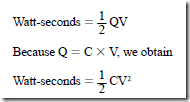
image

• The amount of charge on the plates of a capacitor is a function of the current and time.

1. As the value of the current increases, less time is required to charge the capacitor fully.

2. The time required for a given voltage to build up across the capacitor can be con- trolled by increasing or decreasing the charging current

image

where T is the Greek letter tau, the letter symbol for a time constant expressed in seconds.

• One time constant is the time, in seconds, required for a completely discharged capacitor to charge to 63% of the source voltage.

1. For all practical purposes, it is assumed that the capacitor is fully charged at the end of five time constants.

2. For all practical purposes, it is assumed that a fully charged capacitor will be completely discharged at the end of five time constants of discharge.

• The relationship of the current to the supply voltage for a capacitor being charged can be found at any instant:

image

• When connecting an electrolytic capacitor, the plates must be properly connected.

1. For the wet electrolytic capacitor, the dielectric will repair itself after being punctured as a result of reversed connections.

2. If the connections of the dry electrolytic capacitor are reversed, the dielectric is permanently damaged.

3. The electrolytic capacitor cannot be used in an alternating-current circuit. How- ever, a nonpolarized electrolytic capacitor can be used in ac circuits.

Achievement Review

1. List three factors that affect the capacitance of a capacitor.

2. Define the basic unit of measurement of capacitance.

3. A capacitor takes a charge of 0.05 coulomb (C) when connected across a 250-V source. Determine the capacitance of the capacitor in microfarads.

4. Explain what is meant by the term dielectric constant.

5. A paper capacitor consists of two aluminum foil plates, each 10 ft long and 1.5 in. wide. The waxed paper separating the two plates has a thickness of 0.04 in. The dielectric constant is assumed to be 2. Determine the capacitance of the capacitor, using both formulas:

image

6. Three capacitors have ratings of 20 p,F, 60 p,F, and 30 p,F, respectively. These capacitors are connected in parallel across a 220-V dc source. Determine

a. the total capacitance of the three capacitors connected in parallel.

b. the total charge, in coulombs, taken by the three capacitors in parallel when connected across a 220-V dc source.

7. The three capacitors in question 6 are connected in series across a 220-V dc source. Determine

a. the total capacitance of the three capacitors connected in series.

b. the total charge, in coulombs, taken by the three capacitors in series when connected across a 220-V dc source.

8. Explain what is meant by the term dielectric strength rating.

9. List five practical applications for capacitors.

10. Determine the energy, in watt-seconds, stored in a 100-p,F capacitor when connected across a 400-V dc source.

11. A 100-p,F capacitor is connected in series with a 500-V dc voltmeter across a 400-V dc supply. The voltmeter has a resistance of 1000 D/V.

a. Determine the time, in seconds, represented by one time constant for this RC series circuit.

b. Determine the voltage across the capacitor plates at the end of one time constant when the capacitor is on charge.

12. Using the circuit given in question 11, determine

a. the voltage across the capacitor plates at the end of two time constants, when the capacitor is charging.

b. the voltage across the capacitor plates, at the end of five time constants, when the capacitor is charging.

13. Using the circuit given in question 11, determine the voltage across the plates of the capacitor, at the end of one time constant, when the capacitor is discharging.

14. At the end of one time constant, what is the charging current in amperes for the RC series circuit given in question 11?

15. Determine the time constant, in seconds, for an inductor coil with an inductance of 0.5 H and a resistance of 10 D.

16. If the inductor coil in question 15 is connected across a 120-V source, determine

a. the initial current, in amperes, at the instant the circuit is energized.

b. the current, in amperes, at the end of one time constant after the circuit is energized.

c. the current, in amperes, at the end of two time constants after the circuit is energized.

17. When the inductor coil in question 16 is deenergized, determine the value of the decaying current in amperes

a. at the end of two time constants.

b. at the end of five time constants.

18. a. Explain the difference between a wet and a dry electrolytic capacitor.

b. Where are electrolytic capacitors used?

19. Name four other types of capacitors, in addition to the electrolytic capacitor, that were described in this unit. Briefly describe the material used for the plates and the dielectrics of each type.

20. In schematic wiring diagrams, the curved portion of the symbol for a fixed capaci- tor should be connected in a particular manner. Explain what is meant by this statement.
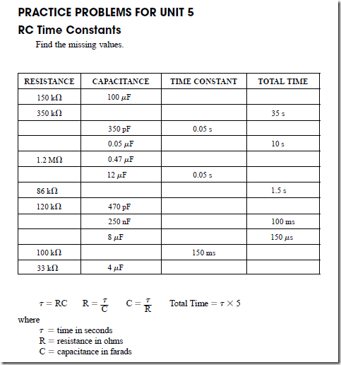
image


Alternating-Current Circuits Containing Resistance : Power in watts , Electrical energy , Measurement of energy and Average current and voltage

POWER IN WATTS

In dc circuits, the power in watts is equal to the product of volts and amperes. For ac circuits, the power in watts at any instant is equal to the product of the volts and amperes at that same instant. However, the average power of ac circuits is not always the product of the effective values of the voltage and current. Because many of the loads supplied by ac circuits have inductive effects, such as motors, transformers, and similar equipment, the current is out of phase with the voltage. As a result, the actual power in watts is less than the product of the voltage and current.

When the current and voltage are in phase in an ac circuit, the average power for a complete cycle is equal to the product of the RMS voltage and the RMS current. In the noninductive circuit shown in Figure 2–1, an ac generator supplies a sine wave of voltage. This voltage has a maximum value of 141.4 V and is applied across the terminals of the 100-D noninductive heating element. The sine wave of current for this circuit is in phase with the voltage sine wave. The maximum current is 1.414 A.

Watts are often called true power in ac circuits. Electricity is a form of pure energy, and in accord with physical laws, energy cannot be created or destroyed, but its form can be changed. Watts is a measure of the amount of electrical energy converted into some other form. In the case of a heating element, it measures the amount of electrical energy converted into thermal energy. In the case of a motor, it is a measure of the amount of energy converted into kinetic energy.

Plotting a Power Curve

It was stated previously that the power at any instant is equal to the product of the volts and amperes at that instant. If the product of the instantaneous values of voltage and current is obtained at fixed increments of electrical time degrees, a power curve can be plotted. Table 2–2 lists the instantaneous values of voltage, current, and power in watts for 15° intervals from 0° to 360°, or one cycle.

Figure 2–6 shows the voltage and current sine waves and the power curve plotted from the data given in Table 2–2. The power curve, indicated by “W” in Figure 2–6, gives the instantaneous power in the circuit at any point in the 360° time period of one cycle.

The Power Curve. It can be seen that all points on the power curve in Figure 2–6 are positive for this ac circuit. During the first alternation of the cycle, both the current and the voltage are positive. As a result, the power curve is also positive. During the second alternation of the cycle, both the current and the voltage are negative. However, the power curve is still positive because the power is the product of a negative current and a negative voltage. The power curve is represented above zero in a positive direction. This means that the load is taking power (in watts) from the source of supply. In this circuit, the voltage and current are acting together at all times. In other words, they are in phase. Thus, the power is positive in both alternations of the cycle.

image

Now, if a dashed line is drawn across the power curve at the 100-watt (W) level on the vertical axis, the areas of the curve above the dashed line will just fit the shaded valleys of the curve below this line. In other words, the average power for the time period of one cycle is 100 W. This value is the product of the effective volts and the effective amperes.

image

The average power is W V X I 100 X 1 100 W. (Note the resemblance between the power curve in Figure 2–6 and the current-squared curve in Figure 2–4. They are the same curve and have the same kind of average, because power current squared times the resistance, P I2R.)

ELECTRICAL ENERGY

The product of effective volts and effective amperes equals the power in watts in any ac circuit having a noninductive resistance load where the current and the voltage are in phase. To obtain a value for the electrical energy in watt-hours, the average power in watts is multiplied by the time in hours. The energy value in kilowatt-hours is obtained by dividing the value in watt-hours by 1000. This procedure was also given in Direct Current Fundamentals as a way of computing the energy in watt-hours and kilowatt-hours. The formulas for electrical energy are

image

In ac circuits containing other than pure resistance, the energy formulas must be modified. Later units of this text will cover this situation.

MEASUREMENT OF ENERGY

Direct Current Fundamentals defined a unit of energy measurement known as the joule. One joule is the energy expended by one ampere at one volt, in one second. Repeated experiments showed that when one ampere was passed through a resistance of one ohm for one second, 0.2389 or 0.24 calorie of heat was liberated. One calorie is the quantity of heat energy required to raise the temperature of one gram of water one degree Celsius. One calorie is equal to 4.186 joules (J). One joule, which is a unit of energy, is equal to one watt-second. For a dc circuit or an ac circuit with a heater unit, the heat in calories is found using the formula

image

In this formula, the I2 R term equals watts and I2 Rt equals the total energy in watt- seconds or joules. If 0.24 calorie (cal) is liberated for each joule of energy expended, the formula becomes

H = 0.24 I2 Rt

The calorie unit of the metric system is widely used. However, it is important that the stu- dent be familiar with another unit called the British thermal unit. The British thermal unit (Btu) is the amount of heat required to raise one pound of water one degree Fahrenheit. Because 1050 J is also required to raise one pound of water one degree Fahrenheit, 1050 J 1 Btu.

For a dc circuit or an ac circuit consisting only of a resistance load, such as a heater unit, the Btu developed in the circuit can be found using the formula

image

If the product in joules or watt-seconds in this formula is divided by 1050, the result is the heat energy in Btu. In the second form of the formula, the value in watt seconds is multiplied by the constant 0.000952. This constant is the decimal part of a Btu represented by one joule.

AVERAGE CURRENT AND VOLTAGE

Almost all alternating-current circuits and calculations use the effective or RMS values of the current and voltage. For example, ac voltmeters and ac ammeters indicate effective values. These values are 0.707 of the instantaneous maximum values.

There are some applications in which the average values of current and voltage are necessary. Some of these include rectifier units that use solid state devices such as diodes and silicon controlled rectifiers (SCRs) to convert alternating current into direct current.

Determining the Average Value

It was pointed out earlier that if an attempt is made to determine the average value of either a sine wave of voltage or current, the obvious procedure is to determine the aver- age value of one alternation of a sine wave. This can be done by taking the average of the ordinates (values on the Y axis) at fixed increments in electrical degrees for one alternation. Figure 2–7 shows the ordinates at 10° intervals for 180° or one alternation.

Another method of determining the average value of a sine wave is to measure the area of the alternation between the wave and the zero reference line. A device called a planimeter is used to measure this area. If the area is then divided by the length of the baseline and multiplied by the ordinate scale, the result will be the average value of the alternation.

As shown in Figure 2–7, the average value of the maximum instantaneous value of a sine wave is 0.637. Because the effective or RMS value is 0.707 of the maximum value, a ratio can be made between the effective value and the average value. This ratio is 0.707 –: 0.637 1.11. This value is called the form factor and is equal to the effective value divided by the average value.

Full-Wave Rectifier

Figure 2–8 shows a resistance-type load connected across the output of a full-wave rectifier. The full-wave rectifier causes both alternations of the cycle to be above the zero reference line in a positive direction. Even though the voltage and the resultant current at the resistance load are pulsating, they do not reverse direction. If a dc voltmeter is

image

image

connected across the resistance load, as shown in Figure 2–8, the meter will indicate a value of 0.637 of the instantaneous maximum voltage. The dc voltmeter has a d’Arsonval movement, which operates on the same principle as a dc motor. This means that the deflection of the needle is determined by the average torque exerted on the movement for a time period of 360 electrical degrees. The resulting indication is the average value for the two alternations.

If the instantaneous maximum value of both alternations in Figure 2–8 is 350 V, then the average value indicated by the voltmeter is

image

Half-Wave Rectifier

Half-wave rectifiers (Figure 2–9) eliminate one half of the waveform and retain the other. Depending on the rectifier, it could eliminate the negative half and retain the positive half or eliminate the positive half and retain the negative half. Regardless, the output of a half-wave rectifier consists of only one half of the 360° cycle. Compare this with the full- wave rectifier, which inverts both halves of the waveform. The example shown in Figure 2–9 assumes that the negative half of the ac waveform has been eliminated.

The resistance load shown in Figure 2–9 is connected to the output of a half-wave rectifier. For half of each time period of 360 electrical degrees, there is no voltage or cur- rent. Therefore, the voltmeter will indicate the average of the one alternation over the 360° time period. This average is half of 0.637, or 0.318.

If the circuit in Figure 2–9 has a maximum instantaneous voltage of 350 V, the volt- meter indication will be

image

image

Measuring AC Voltages

Some manufacturers of dc instruments modify the circuit connections and the scale calibrations to measure ac voltages and currents. Direct-current instruments have uniform scale graduations and markings for the entire scale range. AC voltmeters and ac ammeters lack this uniformity. Thus, it is sometimes difficult to obtain accurate readings. This is the case near the lower end of the scale because of the nonlinear scale graduations.

Figure 2–10 shows how ac voltages can be measured using a dc voltmeter with a full-wave bridge rectifier. The small rectifier section is contained within the instrument. In general, silicon rectifiers are used in meters. The rectifiers permit electron flow in one direction only. The full-wave dc output of the rectifier is impressed directly across the terminals of the dc voltmeter.

The dc voltmeter with a full-wave rectifier, shown in Figure 2–10, is connected across an ac voltage source. The instrument indicates 108 V. This value is an average value equal

image

to 0.637 of the instantaneous maximum value. If the losses in the rectifier can be neglected, then the actual effective value of ac voltage is

imageIn other words, the form factor of 1.11 is applied as a multiplier to the dc voltmeter reading to obtain the effective value of ac volts. To eliminate the need to multiply the average voltage value by the form factor to obtain the effective voltage, the instrument is rescaled to read effective values. This is done by multiplying the original scale values by 1.11 and remarking the scale.

It is sometimes necessary to determine different values of voltage. The voltage ratings of solid state devices, for example, are given as PIV (peak inverse voltage) or PRV (peak reverse voltage). This is the value of voltage the device can withstand without being dam- aged. Both of these ratings list the peak value. AC voltmeters generally indicate the RMS value, not the peak value. If a solid state component is to be connected into an ac circuit, it is generally necessary to determine the peak value to make certain the component will not be damaged.

PROBLEM

Statement of the Problem

A diode is used as a half-wave rectifier. The diode has a PIV rating of 150 volts. Can it be connected to a 120-V RMS circuit without damage?

Solution

Determine the peak value of the ac circuit.

image

The diode will be damaged if it is connected to the 120-V ac line.

The chart in Figure 2–10 can be used to determine different voltage values.

SUMMARY

• An incandescent lighting load and a heating load, such as a heater element, are noninductive resistive loads. For a circuit with such a load, the current waveform is in phase with the voltage waveform.

In phase means that the current and the voltage waveforms of a circuit are zero at the same time and reach their maximum values at the same time and in the same direction.

• Ohm’s law may be applied directly to ac circuits having a resistive load.

• In a resistive ac circuit, inductance, hysteresis effects, and eddy current effects may be neglected.

• Alternating current must be measured using an ac ammeter. All standard ac ammeters and voltmeters indicate effective or RMS values.

• The relationship between maximum and effective values is

image

• The effective value of ac is based on its heating effect and not on the average value of a sine-wave pattern.

• An effective ac current of one ampere will produce heat in a given resistance at the same rate as one ampere of direct current.

• The heating effect of ac varies as the square of the current (watts I2 R).

• The product of the effective voltage and the effective current in amperes gives the power in watts in ac circuits when the current and voltage are in phase.

• Instantaneous values of current can be squared and plotted to give a curve of current- squared values for one cycle. The resulting curve is the power curve. All current-squared values are positive. (Recall that when two negative numbers are multiplied, the product is positive.)

• The power curve gives the instantaneous power in the circuit at any point in the 360° time period of one cycle.

• Because the current squared value is always positive and indicates the instantaneous power available in the circuit, the load takes power (in watts) from the source of supply during the complete cycle.

• The average power in watts of an ac circuit may be less than the product of the voltage and current. (In circuits containing other than pure resistance, the energy formulas must be modified.)

image

(In circuits containing other than pure resistance, the energy formulas must be modified.)

• One joule is the energy expended by one ampere at one volt, in one second.

• One calorie is the quantity of heat energy required to raise the temperature of one gram of water one degree Celsius.

• Relationships between joules, calories, and watt-seconds are as follows:

image

• Average values of current are used by rectifiers, vacuum-tube units, and dc instruments used with silicon rectifiers to measure ac values.

• A d’Arsonval movement operates on the same principle as a dc motor. The deflection of the needle is determined by the average torque exerted on the movement for a period of 360 electrical time degrees.

• DC instruments have uniform scale graduations and markings for the entire scale. AC instruments have nonlinear scale graduations with inaccuracies toward the lower end of the scale.

• An ac instrument indicates the effective value on the scale (0.707 X maximum value).

A dc instrument with a silicon rectifier section, used to measure ac, will indicate the average value (0.637 X maximum value). Therefore, the dc instrument must be rescaled using a form factor multiplier.

• Form factor is a ratio between the effective value and the average value:

image

clip_image013clip_image013[1]

Achievement Review

1. Explain what is meant by the term effective current.

2. Show how the term root-mean-square current was derived.

3. An ac voltmeter connected across the terminals of a heating element of an electric stove indicates a value of 240 V. What is the maximum instantaneous voltage impressed across the heating element?

4. An ac sine wave has an instantaneous maximum value of 7 A. What is the indication of an ac ammeter connected in this circuit?

5. A noninductive heater element with a resistance of 60 D is supplied by a voltage that has a pure sine-wave shape. The instantaneous maximum value of the voltage is 120 V.

a. What is the instantaneous value of the voltage 30° after the voltage is zero and increasing in a positive direction?

b. What is the effective value of the current?

c. Show the relationship between the voltage and current sine waves for one complete cycle.

6. In question 5, what is the power in watts taken by the heater unit?

7. What is meant by the term in phase?

8. In question 5, what is the instantaneous value of current in amperes at 270 electrical degrees?

9. Twenty-four incandescent lamps are connected in parallel across a 120-V, 60-Hz supply. Twenty of the lamps are rated at 60 W, 120 V. Each lamp has a hot resistance of 240 D. The remaining four lamps are rated at 300 W, 120 V. Each of these lamps has a hot resistance of 48 D. (Assume that the incandescent lamps are pure resistance.)

a. Find the total current in amperes.
b. What is the total power in watts?

10.a. If the load in question 9 is operated 5 h each day during a 30-day billing period, what is the total energy consumed in kilowatt-hours?

b. What is the total cost at $.04 per kilowatt-hour to operate the lighting load for the 30-day billing period? 

11. A noninductive heater element with a resistance of 5 D is connected across a 60-Hz source. The supply has a sine-wave voltage with an instantaneous maximum value of 141.4 V.

a. Determine the power in watts taken by the heater unit.

b. What is the energy, in kilowatt-hours, taken by the heater unit in one month if it is operated 5 h per day for a period of 20 days?

12. The nameplate rating of an electric iron is 120 V, 10 A. The heating element of this appliance is almost pure resistance with the current and voltage in phase.

a. Determine the power in watts taken by the appliance.

b. Calculate the resistance of the heater element.
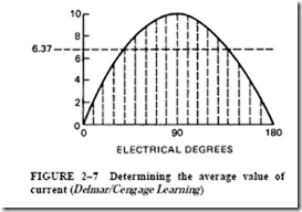
13. Define (a) calorie; (b) British thermal unit (Btu).

14. It is desired to raise the temperature of one quart of water in a coffee percolator from 18°C to 100°C in 9 min. The supply voltage is 120 V.

a. What is the wattage required by the heater unit to bring the water to a boiling temperature in 9 min?

b. What is the resistance of the heater unit?

c. Determine the current taken by the heater unit.

[Note: one quart of water 2.08 pounds (lb); 453.6 grams (g) 1 lb.]

15. An electric hot-water heater is used to heat a 20-gallon (gal) tank of water from 60°F to 130°F in 100 min.

a. Determine the wattage rating of the heater unit

b. Assuming that the heater unit is used on a 230-V, 60-Hz service, find

(1) the current in amperes taken by the heater unit.

(2) the resistance of the unit.

16. When does the product of effective volts and effective amperes equal the power in watts in an ac circuit?

17. A full-wave rectifier supplies a pulsating dc voltage similar to the one shown in Figure 2–8. A voltmeter connected across the noninductive resistance load reads 250 V. What is the instantaneous maximum voltage impressed across the load?

18. Explain what is meant by the term form factor.

19. In Figure 2–11, a half-wave rectifier with a negligible resistance supplies a noninductive resistance load. A dc voltmeter connected across the load reads 54 V.

a. Determine the instantaneous maximum voltage.

b. What is the effective ac input voltage?

image

20. Show the type of rectified dc voltage that would be impressed across the load resistance in question 19.

PRACTICE PROBLEMS FOR UNIT 2 Peak, RMS, and Average Values

Find the missing values.

image