Three-Phase Systems : Introduction , Three-phase voltage , Phase sequence and The wye connection.

Three-Phase Systems
INTRODUCTION

Most alternating-current energy is generated by three-phase generators. This energy is then distributed over three-phase transmission systems. The three-phase circuits used are actually three single-phase circuits combined into one circuit having either three or four wires. Single-phase motors and other single-phase loads may be operated from a three- phase circuit.

Unit 1 gave several reasons why three-phase service is preferred to single-phase service for many applications. The rest of this section is a review of these reasons.

1. For given physical sizes of three-phase motors and generators, the horsepower ratings of the motors and the kVA ratings of the generators are larger. A three-phase generator or an induction motor has a capacity that is about 150% that of a single- phase machine having a comparable frame size.

2. The power delivered by a single-phase circuit is pulsating. Figure 2–7 showed the sinusoidal wave patterns of voltage, current, and power for a resistive load. At unity power factor, when the current and the voltage are in phase, the power is zero twice in each cycle. When the current and the voltage are out of phase, the power is zero four times in each cycle. In certain parts of each cycle, the power is negative. Pulsating power is supplied to each of the three single-phase circuits that make up the three-phase system. However, the total power delivered to the balanced three-phase circuit is the same at any instant. As a result, the operating characteristics of three-phase motors and other machines are superior to those of similar single-phase machines.

3. A balanced three-phase, three-wire circuit having the same voltage between the line wires uses only 75% of the copper required for a single-phase, two-wire circuit. Both circuits have the same kVA capacity, voltage rating, length of circuit, and efficiency of transmission.

THREE-PHASE VOLTAGE

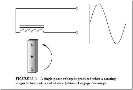
Figure 10-1 illustrates a single-phase alternator. A coil of wire is cut by a rotating magnetic field. Because the magnet contains both north and south magnetic poles, the induced voltage will alternate positive and negative values. The frequency of the ac voltage is determined by the speed of the rotating magnet.

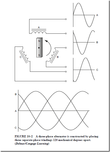
Figure 10-3 illustrates the construction of a three-phase alternator. In this example three separate phase windings are spaced 120 mechanical degrees apart. The rotating magnet will induce voltage into each winding. Due to the placement of the phase wind- ings, the three induced voltages will be 120 electrical degrees apart. This example does not illustrate how the separate phase windings are connected together to form common three-phase connections.

In practice, the coil windings are connected so that only three or four conductors are required to supply a three-phase circuit. There are two standard methods of connecting the

image

single-phase windings of generators, motors, transformers, and other devices to form three- phase circuits. These methods are known as the wye connection and the delta connection. See Figures 10–3 and 10–10.

PHASE SEQUENCE

The phase sequence, or the phase rotation, is the order in which the three voltages of a three-phase circuit follow one another. For example, phase A, in Figure 10–2, starts to rise in a positive direction at zero electrical degrees. At the same instance in time, phase B is positive and heading in the negative direction while phase C has almost reached its peak negative position. These three voltages are 120 electrical degrees apart. Phase sequence is also expressed as phase rotation. When three-phase voltage is connected to a three-phase motor, a rotating magnetic field is produced inside the motor. The direction of rotation is determined by the phase sequence. The direction of the rotating magnetic field can be reversed by changing any two of the three-phase lines connected to the motor. The phase sequence or phase rotation can also be determined by connecting an oscilloscope to the lines to observe the relative position of the different sine wave voltages or by connecting a phase rotation meter to the three lines.

THE WYE CONNECTION

The wye connection is the most commonly used way of connecting the three single-phase windings of three-phase generators. The three coil or phase windings are placed in the slots of the stationary armature. This armature is called the stator. The

image

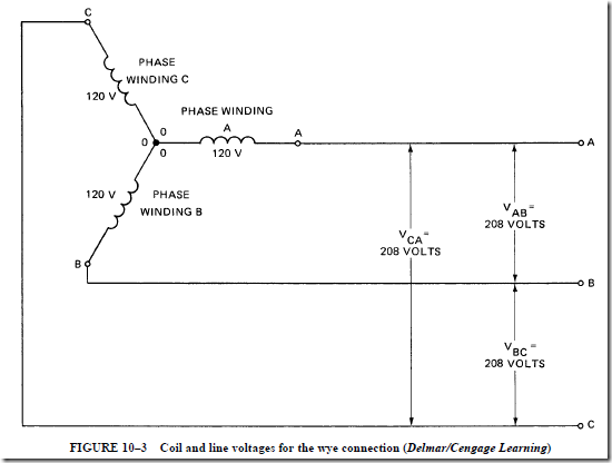
windings are placed so that the three induced voltages are 120 electrical degrees apart. If the ends (marked 0) of each of the phase windings are connected at a common point and the beginnings of the windings (marked A, B, and C) are brought out as the three line leads, the resulting arrangement is the wye connection. Figure 10–3 shows the schematic diagram of a three-phase wye connection.

image

The Phase Voltages

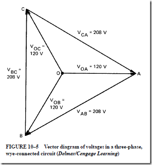
The induced voltage in each phase winding is called the phase voltage. The voltage across the line wires is called the line-to-line voltage. If the voltage induced in each phase winding is 120 V, then the voltage across each pair of line wires is 208 V. Thus, the volt- ages between A and B, B and C, and C and A are all 208 V.

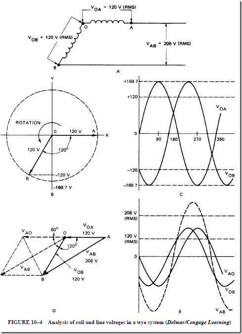
Phase Voltages Are Out of Phase. The two-phase voltages connected together do not add up to 240 V because they are 120° out of phase. Refer to Figure 10–4 during the following discussion of this statement. The phase windings OA and OB are shown in this figure.

Unit 2 stated that the voltages given in ac problems are the effective (RMS) values of the sinusoidally varying voltages. Thus, the actual voltage of phase A (V in Figure 10–4C. This sinusoidal waveform has an effective value of 120 V. V ) is shown is a similar sinusoidal waveform that reaches its maximum value 120 electrical degrees later than does V .

The student should realize that this 120° difference is due to the position of the winding in the generator.

The vector diagram in Figure 10–4B shows that the phase voltages V and V are separated by 120°. As explained in the section on vectors in Unit 3, each voltage vector

image

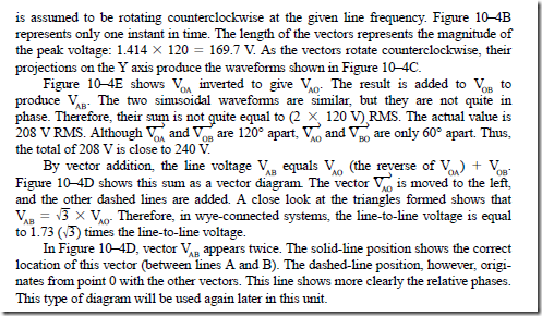
is assumed to be rotating counterclockwise at the given line frequency. Figure 10–4B represents only one instant in time. The length of the vectors represents the magnitude of the peak voltage: 1.414 X 120 = 169.7 V. As the vectors rotate counterclockwise, their projections on the Y axis produce the waveforms shown in Figure 10–4C.

image

Vector Diagram of Voltage

Figure 10–5 is a vector diagram for a three-phase, wye-connected circuit. The diagram shows the three coil voltages and the three line-to-line voltages. Only the voltage relationships for a three-phase circuit have been discussed so far.

What are the current relationships in a three-phase, wye-connected system?

image

Current Relationships

The line current and the phase winding current are the same. These currents are equal because each phase winding is connected in series with one of the three line wires. The following statements give the relationships between the coil and line currents and the voltage in a balanced three-phase wye system.

• The line voltage is equal to �3 times the phase, or coil winding, voltage in a balanced three-phase, wye-connected system.

• The line current values and the phase winding current values are the same in a balanced three-phase, wye-connected system.

Three-Phase, Wye-Connected Circuit

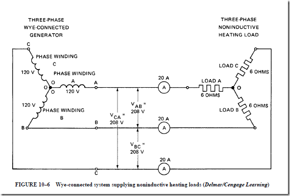
The schematic diagram shown in Figure 10–6 is for a three-phase, wye-connected generator supplying current to a three-phase, noninductive heating load. Kirchhoff’s current law states that the sum of the currents at a junction point in a circuit network is always zero. Therefore, at the source junction (O), the vector sum of the current is zero. Similarly, the vector sum of the three currents at the junction (O) of the heating loads is zero. The currents in the three-phase, three-wire, wye-connected system shown in Figure 10–6 may be unequal because of an unbalanced load. However, the vector sum of the currents at either junction is still zero.

image

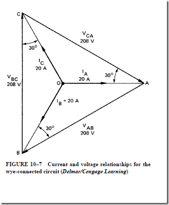
Currents and Voltages in a Wye System

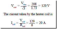
Figure 10–7 is a vector diagram of the currents and voltages for the wye-connected circuit. This circuit operates at a unity power factor. The load shown in Figure 10–6 consists of three noninductive heating elements. Each element has a resistance of 6 n. For a line voltage of 208 V, the voltage across each heater element is

image

Each 120-V phase voltage in this three-phase generator is in phase with its own coil current of 20 A. However, for a unity power factor, there is a phase angle between the line voltage and the line current, which is also the coil current. This phase angle is 30°, as shown in the vector diagram. Note that the coil voltage (V) is in phase with the coil current, I . Also, the coil voltage, V , is in phase with the current I , and the coil voltage V is in phase with the current I . There is a phase angle of 30 electrical degrees between each of

image

the following: the line voltage V and the line current I , the line voltage V and the line

current I , and the line voltage V and the line current I .

For resistive loads, the unity power factor causes the line current to lead the line voltage by 30°. Thus, the power factor angle is measured between the coil voltage and the coil current.

Balanced Wye-Connected Motor

Figure 10–8 shows a balanced three-phase, wye-connected motor load supplied from a three-phase, wye-connected source. The angle of lag of each coil current behind its respective coil voltage is 40 electrical degrees. In other words, the phase angle (8) of the power factor is 40°.

The vector diagram in Figure 10–9 shows the relationship between the current and voltage values for the three-phase motor circuit shown in Figure 10–8. The angle 8 (the power factor angle) is the angle between the coil voltage and the coil current.

 

Series–Parallel Circuits : Admittance, conductance, and susceptance

Series–Parallel Circuits
ADMITTANCE, CONDUCTANCE, AND SUSCEPTANCE Admittance

Impedance is the measurement of the opposition to electron flow in a circuit containing resistance and reactance. The unit of admittance is a measurement of the ease of electron flow through a circuit or component containing resistance and reactance. This means that admittance is the inverse, or reciprocal, of impedance. The unit of measurement for admittance is the siemens (abbreviated as S). (Formerly the unit of admittance was known as the mho, .) Admittance is indicated by the letter Y.

The relationship between admittance, in siemens, and the impedance, in ohms, is

image

Conductance

Conductance is a measurement of the ease of electron flow through a resistance. Conductance, like admittance, is measured in siemens. For dc circuits and ac circuits containing only noninductive resistance, the conductance is the reciprocal of the resistance. For ac circuits containing resistance and reactance, the conductance (G) is equal to the resistance divided by the square of the impedance:

G = R ÷ Z2

Susceptance

Susceptance measures the ease of electron flow through the reactance of an ac circuit. Like admittance and conductance, the unit of susceptance is the siemens. Susceptance (B) is equal to the reactance, in ohms, divided by the square of the impedance:

B = X ÷ Z2

Susceptances (B) in parallel and conductances (G) in parallel are added.

Relationship between Admittance, Conductance, and Susceptance The relationship between the admittance, the conductance, and the susceptance is the same as the relationship between the impedance, the resistance, and the reactance, as shown in Figure 9–1.

The admittance triangle in Figure 9–1 shows that the admittance (Y) is the hypotenuse of a right triangle:

image

PROBLEM 1

Statement of the Problem

The schematic diagram of a series–parallel circuit is shown in Figure 9–2. The series part of the circuit contains resistance and inductive reactance. The GBY method is to be used to find the following circuit values:

1. The total impedance, in ohms

2. The current for the series–parallel circuit

3. The power factor of the series–parallel circuit

image

Solution

1. This problem is solved by considering the circuit in sections. The values of the various quantities for sections A–B and C–D of the circuit in Figure 9–2 are shown in this table. The values in each circuit section connected in parallel are placed in the table as a convenient reference.

image

image

image

In the series part of the circuit between F and G, the resistance is 4 W and X is 9 W. For  the entire circuit, the resistance of the parallel section (E–F) is added to the resistance of the series portion (F–G):

image_thumb[2]

PROBLEM 2

Statement of the Problem

In the series–parallel circuit shown in Figure 9–3, both the parallel and the series sections contain resistance and reactance.

image_thumb[3]

The GBY method is to be used to determine the following values for this circuit:

1. The total impedance, in ohms

2. The current indicated by the ammeter

3. The power factor of the series–parallel circuit

Solution
1. The following table lists the given values for the parallel branches (A–B and C–D) of the circuit.

image_thumb[4]

image_thumb[5]

image_thumb[6]

SUMMARY
• The GBY method of solving ac network circuits is commonly used because only basic mathematical processes are needed.
1. G = conductance. This unit is a measurement of the ease of electron flow through a circuit or component containing resistance.
a. It is measured in siemens.
b. It is the inverse or reciprocal of resistance in a dc circuit or an ac circuit containing only noninductive resistance:

image_thumb[7]
2. B = susceptance. This unit is a measurement of the ease of electron flow through the reactance of an ac circuit.
a. It is measured in siemens.
b. It is expressed as the ratio of the reactance and the impedance squared:

image_thumb[8]3. Y = admittance. This unit is a measurement of the ease of electron flow through a circuit or component containing resistance and reactance (impedance).
a. It is measured in siemens.
b. It is the inverse or reciprocal of impedance.
c. The relationship between admittance, in siemens, and the impedance, in ohms, is

image_thumb[9]

• The relationship between the admittance, the conductance, and the susceptance is the
same as the relationship between impedance, resistance, and reactance.
• The admittance (Y) is the hypotenuse of a right triangle:

image_thumb[10]
• To determine the total susceptance, in siemens, for parallel branches in an ac circuit, the susceptance of the capacitor branch must be subtracted from the susceptance values of the other two branches.
1. The inductive reactance (XL) and the capacitive reactance (XC) cause opposite effects in an ac circuit.
2. The reciprocal values of XL and XC, expressed as susceptance, in siemens, also have opposite effects.
• The total admittance, in siemens, for a parallel circuit with a number of branches is

image_thumb[11]

• The combined resistance for an ac circuit containing series and parallel branches is the sum of the resistance in the series branches and the resistance in the parallel branches, where the resistance in the parallel branches is

image_thumb[12]

• The combined reactance (XL) for a circuit with series and parallel branches is the sum of the reactance in the series branches and the reactance in the parallel branches, where the reactance in the parallel branches is

image_thumb[13]

Achievement Review
1. Explain the meaning of the following terms:
a. Admittance
b. Conductance
c. Susceptance
2. In the series–parallel circuit shown in Figure 9 –4, determine
a. the admittance, in siemens, of the parallel section of the circuit between points E and F.
b. the total impedance of the series–parallel circuit.

image_thumb[14]

3. Using the circuit given in question 2, determine
a. the reading of the ammeter.
b. the current in amperes in the A–B circuit branch.
c. the power factor of the entire series–parallel circuit.
d. the total power, in watts, taken by the entire series–parallel circuit.
4. In the series–parallel circuit shown in Figure 9–5, determine
a. the admittance, in siemens, of the three branches connected in parallel.
b. the impedance, in ohms, of the entire series–parallel circuit.

image_thumb[15]

5. Using the circuit given in question 4, determine
a. the total current taken by the entire series–parallel circuit.
b. the current taken by each of the three branches.

6. Using the circuit given in question 4, determine

a. the power factor of the entire series–parallel circuit.
b. the power factor of each branch circuit.
c. the total power, in watts, taken by the series–parallel circuit.


AC Parallel Circuits : Correcting motor power factor

CORRECTING MOTOR POWER FACTOR

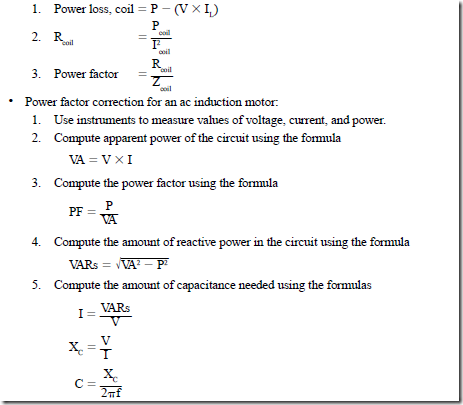
It is sometimes necessary to correct the power factor of a motor. The following procedure can be used to perform this task. Before the power factor of a motor can be corrected, it must first be determined how much out of phase current and voltage are with each other. In the circuit shown in Figure 8–17, a wattmeter, an ammeter, and a voltmeter are used to measure circuit values. The voltmeter indicates a voltage of 480 V connected to the motor. The ammeter shows a total current draw of 250 A, and the wattmeter shows the true power of the circuit to be 96 kW.

image

Computing Apparent Power

The apparent power or volt-amperes of the circuit can be determined by multiplying the applied voltage by the total current:

image

image

Computing Power Factor

Because both the true power and the apparent power are known, the power factor of the circuit can be found using the following formula:

imageCalculating the Reactive Power

The amount of reactive power or VARs (volt-amperes-reactive) can be determined using the formula

image

The 72 kVARs represents the amount of reactive power in the circuit. Because this reactive component is caused by a motor, it is inductive. If the power factor is to be corrected, the same amount of capacitive VARs must be added to the circuit. The capacitive VARs will cancel the inductive VARs, and the current and voltage will be in phase with each other.

Calculating the Capacitance Needed

To calculate the amount of capacitance needed, first determine the amount of current that must flow to produce 72 capacitive kVARs. This can be found by using the following formula:

image

The amount of capacitive reactance needed to produce a flow of 150 A through a capacitor can now be computed using the following formula:

image

The amount of capacitance needed to produce a capacitive reactance of 3.2 n at 60 Hz can now be computed using the formula

image

where C = 0.008289 F or 828.9 ,uF If a capacitance of 828.9 ,uF is connected across the motor as shown in Figure 8–18, the power factor will be corrected to unity or 100%.

image


clip_image012

FIGURE 8–18 A capacitor corrects power factor for the motor (Delmar/Cengage Learning)

Advantages of Unity Power Factor. Utility companies and industrial plants try to keep the power factor of their ac circuits as close to unity as possible. The unity power factor is desirable because of the following:

1. The quadrature current in the line wires causes I2 R losses, just as the in-phase current causes power losses in the circuit conductors. Therefore, if the power factor is raised to a value near unity, the power losses in the line wires are reduced and the efficiency of transmission is increased.

2. If the power factor is corrected to a value near unity, there is less voltage drop in the line. As a result, the voltage at the load is more constant.

3. AC circuits operated at a high power factor improve the efficiency and operating performance of ac generators and transformers supplying these circuits.

SUMMARY

• The voltage across any branch circuit in a parallel arrangement, neglecting line voltage drops, is the same as the line voltage.

• In the analysis of series circuits, the current is used as the reference vector.

• In the analysis of parallel circuits, the voltage is used as the reference vector. Thus, all angles in the analysis of parallel circuits are measured with respect to the voltage vector.

• For an ac parallel circuit with branches containing only pure resistance, the calculations are the same as those for a direct-current parallel circuit:

image

For an ac parallel circuit, the current in each branch circuit containing a pure resistive component is in phase with the line voltage. Thus, the power factor is

image

• In a parallel ac circuit containing R, X , and X components, the total line current may be out of phase with the line voltage. In this case, the line current must be calculated using vectors:

image

A parallel circuit with branches containing R, X , and X has the following properties as determined by calculation:

image

The current in the inductive branch lags the same line voltage by 90°.

and I are 180° out of phase with each other, and (IL – IC) yields a net quadrature current. The line current consists of an in-phase component and a leading or lagging quadrature component:

image

2. Power. All of the power taken by this circuit is used in the resistive branch.

Because the currents taken by the coil branch and the capacitor branch are 90° out of phase with the line voltage, no power is taken in either of these branches. The power for the resistance branch is the power for the entire parallel circuit:

image

3. Power factor (PF). The power factor for an ac parallel circuit is determined using either of the following ratios:

image

The net magnetizing VARs supplied by the line is the difference between the VARs required by the coil and the VARs supplied by the capacitor.

• Resonance in ac circuits:

1. Series and parallel resonant circuits having identical values of R, L, and C have the following similarities:

a. The line currents and the line voltages are in phase.

b. The power factors are unity.

c. The values of X and X are equal.

d.The impedances are purely resistive.

2. Series and parallel resonant circuits having the same values of R, L, and C are different in the following respects:

a. The current is at a maximum in a series resonant circuit and at a minimum in a parallel resonant circuit.

b. The impedance is at a minimum in a series resonant circuit and at a maximum in a parallel resonant circuit.

These factors make parallel resonance a useful feature in tuned circuits.

• The current and impedance curves for a parallel resonant circuit are opposite to those for a series resonant circuit. The current equation for the parallel resonant circuit is

image

3. At frequencies above resonance:

image

where IXL is negligible and XL has high values. IL is at a maximum again.

4. The impedance curve is the reciprocal of the current curve:

image

• For a parallel ac circuit containing impedance, the power lost in the coil, the resistance of the coil, and the power factor of the coil are determined as follows:

image

• Advantages of a unity power factor:

1. The quadrature current causes I2 R losses. Correcting the power factor to a value near unity reduces the power losses in the line wires and the efficiency of trans- mission is increased.

2. Correcting the power factor to a value near unity decreases the voltage drop.

As a result, the voltage at the load is more constant.

3. If ac circuits are operated at a high power factor, there is an improvement in the efficiency and operating performance of ac generators and transformers supplying these circuits.

Achievement Review

1. A parallel circuit consists of two branches connected to a 120-V, 60-Hz source.

The first branch has a noninductive resistance load of 50 n. The second branch consists of a coil with an inductance of 0.2 H and negligible resistance.

a. Find the current in each branch.

b. Determine the line current.

c. Determine the power factor of the parallel circuit.

d. Draw a labeled vector diagram for this circuit.

2. A resistance of 40 n is connected in parallel with a pure inductance of 0.24 H across a 120-V, 25-Hz supply.

a. Find the current taken by each branch.

b. Determine the line current.

c. Determine the power factor of the parallel circuit.

d. Determine the combined impedance of the parallel circuit.

e. Draw a labeled vector diagram for the parallel circuit.

3. A 120-V, 60-Hz source supplies a parallel circuit consisting of two branches.

Branch 1 is a noninductive resistance load of 5 n. Branch 2 feeds a 1000- ,uF capacitor with negligible resistance.

a. Determine

(1) the current taken by each branch.

(2) the line current.

(3) the combined impedance of the parallel circuit.

(4) the power factor and phase angle for the parallel circuit.

b. Draw a labeled vector diagram for the parallel circuit.

4. A 240-V, 60-Hz single-phase source supplies a parallel circuit consisting of two branches. Branch 1 has a resistance of 20 n in series with an inductance of

0.04 H. Branch 2 feeds a 50-,uF capacitor with negligible resistance.

a. Determine

(1) the current in each branch.

(2) the total current.

(3) the power factor of branch 1 (containing R and X components in series).

(4) the power factor of the entire parallel circuit.

b. Draw a labeled vector diagram for the parallel circuit.

5. A 240-V, 60-Hz parallel circuit supplies three branches. Branch 1 consists of a noninductive heating load with a resistance of 12 n, branch 2 feeds a pure inductive reactance load of 8 n, and branch 3 is a capacitor having a capacitive reactance of 16 n.

a. Determine

(1) the current taken by each of the three branches.

(2) the total current.

(3) the combined impedance of the parallel circuit.

(4) the circuit power factor.

(5) the total power in kilowatts taken by the parallel circuit.

b. Draw a labeled vector diagram for this circuit.

6. Using the circuit shown in Figure 8–19, determine

a. the current taken by each branch.

b. the power expended in the resistance branch, in watts.

c. the power expended in the coil branch, in watts.

d. the impedance of the coil.

e. the effective resistance and the inductive reactance components of the coil.

image

7. a. Using the circuit in the preceding question, determine

(1) the total current.

(2) the power factor and the phase angle for the inductive branch circuit.

(3) the power factor and the phase angle for the entire parallel circuit.

(4) the combined impedance of the parallel circuit.

b. Draw a vector diagram and label it properly for this circuit.

8. A 125-V, 60-Hz parallel circuit has three branches. Branch 1 has a resistance of 20 n, branch 2 feeds a coil with an inductance of 0.0211 H, and branch 3 supplies a 200-,uF capacitor. The resistances of both the coil and the capacitor are negligible.

Determine

a. the current in each branch.

b. the total current.

c. the power factor for the parallel circuit.

9. Explain the meaning of the term parallel resonance.

10. An ac parallel circuit consists of three branches connected to a 120-V, 60-Hz supply. Branch 1 consists of a noninductive resistance load, branch 2 feeds a coil, and branch 3 supplies a capacitor. The resistances of the coil and the capacitor are negligible. The total line current is 10 A. The power factor of the entire parallel circuit is 90% lagging. The capacitor has a capacitive reactance of 12.5 n.

a. Draw a labeled vector diagram of the circuit.

b. Determine

(1) the current taken by each of the three branches.

(2) the true power in watts taken by the entire parallel circuit.

11. The capacitor in the circuit described in question 5 is changed to one having the proper rating to give a circuit power factor of unity. Determine the following data for the capacitor value that causes the circuit to be in parallel resonance:

a. Rating in VARs

b. Capacitive reactance

c. Rating in microfarads

12. In the circuit given in question 6, there is to be a third branch feeding a capacitor.

This capacitor has the proper rating to correct the power factor to unity. Using the information provided in question 6, determine

a. the rating of the capacitor, in VARs.

b. the capacitive reactance of the capacitor (assume the resistance to be negligible).

c. the rating of the capacitor, in microfarads. Construct a vector diagram for this circuit.

13. A noninductive heater and an ac motor are operated in parallel across a 120-V, 25-Hz source. The heater takes 600 W. The motor takes 360 W at a lagging power factor of 60%. Determine

a. the current taken by each of the two branches.

b. the total current.

c. the circuit power factor.

14. A 120-V induction motor requires 24 A at a lagging power factor of 75%. If a lamp load of 30 A is connected in parallel with the motor, what are the power fac- tor and the phase angle for the entire parallel circuit?

15. Why is it important to maintain a high power factor with alternating-current systems?

16. At full load, a 220-V, 2-horsepower (hp), single-phase induction motor takes 12 A when operated on a 60-Hz service. The full-load power factor is 80% lagging.

At full load, determine

a. the phase current.

b. the power, in watts.

c. the quadrature current.

d. the magnetizing VARs required.

e. the input volt-amperes.

17. The power factor of the circuit in question 16 is to be corrected to a value of unity by connecting a capacitor in parallel with the motor. Determine

a. the rating of the capacitor, in VARs.

b. the capacitive reactance of the capacitor.

c. the rating of the capacitor, in microfarads.

d. the line current after the power factor is increased to 100% or unity.

18. An industrial plant has a load of 50 kW at a power factor of 70% lag, feeding from a 240-V, 60-Hz system. Determine

a. the line current.

b. the capacitor rating, in kilovars, required to raise the power factor to unity.

c. the line current after the capacitor is added to the circuit.

PRACTICE PROBLEMS FOR UNIT 8

Resistive Inductive Parallel Circuits

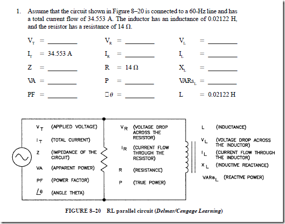
Find the missing values for the following circuits. Refer to Figure 8–20 and the formulas under the Resistive Inductive (Parallel) section of Appendix 15.

image_thumb

image_thumb[1]

Resistive Capacitive Parallel Circuits

Find the missing values for the following circuits. Refer to Figure 8–21 and the formulas listed under the Resistive Capacitive (Parallel) section of Appendix 15.

image_thumb[2]

5. Assume that the circuit shown in Figure 8–21 is connected to a 60-Hz line and has a total current flow of 10.463 A. The capacitor has a capacitance of 132.626 ,uF, and the resistor has a resistance of 14 n.

image_thumb[3]

7. Assume that the circuit in Figure 8–21 is connected to a 600-Hz line and has a current flow through the resistor of 65.6 A and a current flow through the capacitor of 124.8 A. The total impedance of the circuit is 2.17888 n.

image_thumb[4]

8. Assume the circuit is connected to a 1000-Hz line and has a true power of 486.75 W and a reactive power of 187.5 VARs. The total current flow in the circuit is

image_thumb[5]

Resistive-Inductive-Capacitive Parallel Circuits

Find the missing values in the following circuits. Refer to Figure 8–22 and the formulas under the Resistive-Inductive-Capacitive (Parallel) section of Appendix 15.

9. The circuit shown in Figure 8–22 is connected to a 120-volt, 60-Hz line. The resistor has a resistance of 36 n, the inductor has an inductive reactance of 40 n and the capacitor has a capacitive reactance of 50 n.

image_thumb[6]

image_thumb[7]

10. The circuit in Figure 8–22 is connected to a 400-Hz line with a total cur- rent flow of 22.627 A. There is a true power of 3840 W. The inductor has a reactive power of 1920 VARs, and the capacitor has a reactive power of 5760 VARs.

image_thumb[8]

11. The circuit in Figure 8–22 is connected to a 60-Hz line. The apparent power in the circuit is 48.106 VA. The resistor has a resistance of 12 n. The inductor has an inductive reactance of 60 n, and the capacitor has a capacitive reactance of 45 n.

image_thumb[10]

12. The circuit shown in Figure 8–22 is connected to a 1000-Hz line. The resistor has a current flow of 60 A, the inductor has a current flow of 150 A, and the capacitor has a current flow of 70 A. The circuit has a total impedance of 4.8 n.

image_thumb[11]


AC Parallel Circuits : Parallel circuit with branches containing R, Z coil, and XC

PARALLEL CIRCUIT WITH BRANCHES CONTAINING R, XL, AND XC

Figure 8–10 illustrates a parallel circuit consisting of three branch circuits. One branch contains resistance, a second branch contains pure inductance, and the third branch contains capacitance.

PROBLEM 5

Statement of the Problem

For the circuit shown in Figure 8–10, determine the following items:

1. The current taken by each branch

2. The line current

3. The power

4. The magnetizing VARs required by the coil

5. The magnetizing VARs supplied by the capacitor

6. The net magnetizing VARs supplied by the line

7. The power factor and the phase angle for the circuit

8. Total impedance of the circuit

Construct a vector diagram for the parallel circuit.

Solution

1. The current taken by each branch of the circuit is as follows:

Resistance branch:

image

2. The current in the capacitor branch leads the line voltage by 90°. The coil current lags the same line voltage by 90°. In other words, IC and IL are 180° out of phase with each other. I – IC (15 A – 10 A) yields a net quadrature current of 5 A inductive. This means that the line current consists of an in-phase component of 12 A and a lagging quadrature component of 5 A. The line current is

image

3. All of the power taken by this circuit is used in the resistance branch. The currents taken by the coil branch and the capacitor branch are 90° out of phase with the line voltage. As a result, the power taken by either of these branches is zero. The power for the resistance branch is the power for the entire parallel circuit. This value, in watts, can be determined by any one of the following expressions:

image

image

6. The net magnetizing VARs supplied by the line is the difference between the VARs required by the coil and the VARs supplied by the capacitor:

Net VARs = 3600 – 2400 = 1200 VARs

7. The power factor for this parallel circuit may be found using either of two ratios: (a) the ratio of the power in watts to the input volt-amperes, or (b) the ratio of the in-phase current to the total line current. The resulting power factor is lagging. This lag is due to the fact that the quadrature current taken by the coil branch is greater than the current taken by the capacitor branch. The net quadrature current supplied by the ac source lags the line voltage by 90°. The power factor is

image

image

8. The angle fJ for a lagging power factor of 0.9231 is 22.6°. The vector diagram for the parallel circuit with branches containing R, X , and X is shown in Figure 8–11.

9. The total impedance of the circuit can be found using either of the following formulas:

image

image

image

In this formula, X is a positive number and X is a negative number. Therefore, Z will be either positive or negative depending on whether the circuit is more inductive (positive) or capacitive (negative).

Assume a parallel circuit contains a 12-n resistor connected in parallel with an inductor that has an inductive reactance of 8 n and a capacitor that has a capacitive reactance of 16 n. To find the total impedance of this sample circuit using this formula, first determine the value of X:

image

PARALLEL CIRCUIT RESONANCE

The current in a series circuit reaches its maximum value at resonance. At this point, the effects of inductive reactance and capacitive reactance cancel each other. Also, the full line voltage is impressed across the resistance of the circuit. Thus, for the series circuit, the current and line voltage are in phase.

An analysis of a series and a parallel resonant circuit having identical values of R, L, and C will show the following similarities:

1. The line currents and the line voltages are in phase.

2. The power factors are unity.

3. The values of X and X are equal.

4. The impedances are purely resistive.

These similarities may give the impression that both circuits are identical at resonance. However, there are two important differences between series and parallel circuits, which can be seen by looking at the magnitudes of the currents and impedances:

1. The current is at a maximum in a series resonant circuit and at a minimum in a parallel resonant circuit.

2. The impedance is at a minimum in a series resonant circuit and at a maximum in a parallel resonant circuit.

These factors make parallel resonance a useful feature in tuned circuits.

Current and Impedance Discussion

Figure 8–12 shows the current and impedance curves for a parallel resonant circuit. These curves are opposite to those shown for a series resonant circuit. The current equation for the parallel circuit is

image

where IXC is negligible at low frequencies. The capacitive reactance has high values at frequencies below resonance. This means that only very small currents flow. The opposite is true for the inductive branch, where I becomes a maximum value.

For frequencies at resonance, the current equation takes the following form:

image

At resonance, x and X are equal and 180° out of phase. Their currents are also equal and 180° out of phase and thus cancel. The current remaining is the resistive component, I . (Iis at a minimum.) At resonance, it is possible in theory to have the following valR L ues: an inductive current of 10 A, a capacitive current of 10 A, and a line current of 0 A.

At frequencies above resonance, the current equation takes the following form:

image

By examining what happens at frequencies below resonance, the student should be able to analyze the previous resonance case where I becomes a maximum value again.

The impedance curve is the reciprocal of the current curve. The impedance curve is defined by the equation Z = V/I.

image

The parallel circuit shown in Figure 8–10 has a lagging power factor of 0.9231. A larger capacitor may be used in the capacitive branch of the circuit. This increased value causes an increase in the leading current. For example, for a capacitor with X = 16 n, the quadrature current for this capacitor is 15 A leading. The coil in branch 2 of the circuit also requires 15 A. The 15 A taken by the capacitor leads the line voltage by 90°. The 15 A supplied to the coil lags the line voltage by 90°.

Resonant Parallel Circuit

Figure 8–13 shows a parallel circuit in which the coil and capacitor branches each take 15 A. This circuit is a resonant parallel circuit. The 15 A in the coil branch and the 15 A in the capacitor branch are 180° out of phase. As a result, the currents cancel each other. The source supplies the in-phase current only for the resistance load in the circuit. Therefore, the line current is the same as the current taken by the resistor.

PROBLEM 6

Statement of the Problem

For the circuit given in Figure 8–13, determine the following items:

1. The line current

2. The power

3. The power factor and the phase angle

Construct a vector diagram for this parallel resonant circuit.

image


image

PARALLEL CIRCUIT WITH BRANCHES CONTAINING R, Zcoil, AND XC

The circuit shown in Figure 8–15 contains three branches: a wattmeter, which indicates the true power in the circuit; and ammeters, which indicate the line current and the current in each branch.

One branch contains a pure resistance of 30 n. A second branch contains a load that has both resistance and inductance. This is similar to the load shown in Figure 8–8.

As before, the value of Zcoil is not to be confused with the value of Z total coil is used to represent the value of impedance for the coil only, and Z total is used to represent the value of impedance for the entire circuit. Finally, the third branch contains a capacitor with a capacitive reactance of 40 n.

Power Factor for the Circuit

The power factor of the circuit is found by the use of the following expression:

image

The entire circuit has a lagging power factor because the inductive reactive current is more than the current in XC. The phase angle is 29° lagging.

Power Factor for the Impedance Coil

To find the power factor of the impedance branch, the power loss in the coil must be determined first:

image

The current in the impedance coil lags the line voltage. The cosine of this angle of lag is 0.20. Thus, the angle itself is 78.5°.

The Vector Diagram. The angles and current values calculated for this problem are used to obtain the vector diagram shown in Figure 8–16. A graphical solution to the parallel circuit is shown in the following procedure. Steps 1 through 3 require a compass, protractor, and ruler.

1. Lay out the current vectors as shown:

image

This problem can be solved mathematically by resolving the I coil vector (6 A) into a horizontal (in-phase) component and a vertical (quadrature) component. This method is used in the following section on power factor correction.


AC Parallel Circuits : Introduction , Parallel circuit with resistive load , Parallel circuit with branches containing R and XL, Parallel circuit with branches containing R and XC and Parallel circuit with branches containing R and Zcoil.

AC Parallel Circuits
INTRODUCTION

There are more applications in alternating-current work for parallel circuits than for series circuits. Nearly all commercial, industrial, and residential power circuits are connected in parallel. The voltage across any branch circuit in a parallel arrangement is the same as the line voltage. This is true if the voltage drop in the line wires is neglected. Recall from earlier studies that the total (line) current for an ac parallel circuit may not be equal to the arithmetic sum of the current in each of the branch circuits. The currents in the branch circuits may be out of phase. Thus, the total (line) current must be calculated using vectors. The approximate value of the line current can also be found by drawing a vector diagram accurately to scale.

This unit develops methods of analyzing ac parallel circuits. These methods are based on concepts learned in the study of series circuits.

The voltage is constant across each branch of a parallel circuit. Thus, all angles are measured with respect to the voltage vector. This means that the voltage vector is a reference vector.

PARALLEL CIRCUIT WITH RESISTIVE LOAD

The first parallel circuit to be studied has a noninductive resistive load in each branch (Figure 8–1). All of the branch currents for this circuit are in phase with the line voltage. In this case, both the vector sum and the arithmetic sum of the branch currents give the total line current.

This parallel circuit is connected to a 120-V, 60-Hz source. The calculations are the same for an ac parallel circuit with noninductive resistance loads only and for a direct- current parallel circuit.

PROBLEM 1

Statement of the Problem

For the parallel circuit shown in Figure 8–1, find the following quantities:

1. The combined resistance

2. The current taken by each branch

3. The line current

4. The total power taken by the parallel circuit

5. The power factor and the phase angle

6. The vector diagram

image

Solution

1. The combined resistance is obtained by using the reciprocal resistance formula (discussed in Direct Current Fundamentals):

image

2. The current taken by each branch is given by Ohm’s law:

image

3. The total current can be found by either of two methods. The individual branch current values can be added, or Ohm’s law can be applied to the entire parallel circuit. Either method gives a total current of 12 A.

4. The total power taken by the entire parallel circuit is the product of the line voltage and the line current. (These values are in phase.)

image

image

The angle whose cosine is 1.00 is 0°. In other words, the line current is in phase with the line voltage.

6. The vector diagram for this parallel circuit is shown in Figure 8–2. The individual branch current values are placed on the voltage vector. Both the arithmetic sum and the vector sum of the branch currents equal the total line current.

PARALLEL CIRCUIT WITH BRANCHES CONTAINING R AND XL

Another type of parallel circuit has one branch containing a noninductive resistance load and a second branch containing pure inductance (Figure 8–3).

The two branch currents for this parallel circuit are 90 electrical degrees out of phase with each other. The current in the noninductive resistance branch is in phase with the line voltage. The current in the pure inductive branch lags the line voltage by 90°. Thus, the total line current can be found using vector methods.

image

PROBLEM 2

Statement of the Problem

For the parallel circuit shown in Figure 8–3, determine the following:

1. The current taken by each of the two branches

2. The vector diagram for the parallel circuit

3. The total current

4. The power taken by the parallel circuit

5. The power factor for the parallel circuit

6. The phase angle

7. The combined impedance

Solution

1. The voltage across each branch of the circuit is 120 V. The current in each branch of this circuit is as follows:

image

image

2. The current and voltage vector diagram for an RL parallel circuit is shown in Figure 8–4. The vector I is in the negative Y direction. Recall that in series circuits, the vector V was in the positive Y direction. The change in direction does not involve new concepts, but occurs because the reference vector has changed from I to V. The line current is the vector sum of the branch currents and lags behind the line voltage by an angle of 21.5°. (The calculation of this angle is given in steps 5 and 6.)

3. The total line current is really the hypotenuse of the right triangle in Figure 8–4, where

image

4. The power taken by the parallel circuit is used in the first branch containing resistance. No power is taken by the pure inductive load in the second branch. The power for the parallel circuit is

image

5. The power factor of any ac circuit is the cosine of the angle fJ. This value equals the ratio of the power to the input volt-amperes. The power factor is also the ratio of

image

the in-phase current to the total line current. For the circuit in Figure 8–4, the power factor is

image

6. The power factor angle (fJ) is 21.5° lagging.

7. The combined impedance of a parallel circuit is found using Ohm’s law. The impedance formula for a series circuit cannot be used because each parallel branch connected across the line wires tends to reduce the total parallel circuit impedance:

image

Impedance Triangle for Parallel Circuits

In series circuits, the voltage triangle is divided and multiplied by current to obtain the impedance and power triangles, respectively. In parallel circuits, the current triangle is divided by the reference vector V to obtain the impedance triangle (Figure 8–5).

The impedance triangle shown in Figure 8–5 for a parallel circuit does not resemble the series circuit impedance triangle. The impedance formula for a parallel circuit is

image

Another formula that can be used to determine the impedance of resistance and inductive reactance connected in parallel is

image

Assume that a parallel circuit contains a 15-n resistor connected in parallel with an inductor that has an inductive reactance of 20 n. To determine circuit impedance, substitute the values in the following formula:

image


Series Circuits: Resistance, Inductive Reactance,and Capacitive Reactance : Resonance in series circuits and The properties of series resonance.

RESONANCE IN SERIES CIRCUITS

In the solution to problem 1 in this unit, the inductive reactance was greater than the capacitive reactance. As a result, there was a lagging power factor. In problem 2, the capacitive reactance is larger than the inductive reactance and the power factor is leading.

If the inductive reactance equals the capacitive reactance, then V equals V . Because these voltages are 180° out of phase with each other, they will cancel exactly. The effects of both the inductive reactance and the capacitive reactance are now removed from the

image

series circuit. Thus, only the resistance of the circuit remains to limit the current. A circuit for which these conditions are true is called a resonant circuit. The full line voltage appears across the resistance component.

PROBLEM 2

Statement of the Problem

A resonant series circuit is shown in Figure 7–6. The phase angle between the current and the line voltage for this circuit is zero. The power factor is 1.00.

Another way of looking at this circuit is to recognize that the value of the magnetizing VARs required by the coil is equal to the magnetizing VARs supplied by the capacitor. These values cancel each other so that no VARs appear at the input terminals.

Determine the following quantities for the resonant series circuit in Figure 7–6:

1. The impedance

2. The current

3. The voltage across the resistor

4. The voltage across the coil

image

5. The voltage across the capacitor

6. The loss in the resistor, in watts

7. The magnetizing VARs required by the coil

8. The magnetizing VARs supplied by the capacitor

9. The input in volt-amperes

10. The power factor and the phase angle for the series circuit Then develop the vector diagram for the circuit.

Solution

1. The impedance of a resonant circuit is the same as the resistance of the circuit. The formula for impedance is

image

image

3. The voltage across the total resistance of a resonant series circuit equals the line volt- age. It is assumed that there is no resistance in either the coil or the capacitor. The voltage across the lamp load is

image

image

9. The input volt-amperes for the series circuit is the product of the line voltage and the current. The input volt-amperes and the true power are the same in a series resonant circuit:

VA = VI = 120 X 5 = 600 VA

10. Because the true power and the input volt-amperes are the same for this circuit, the power factor is unity. A unity power factor is also obtained from the ratio of the resistance of the resonant series circuit and the input impedance:

image

THE PROPERTIES OF SERIES RESONANCE

Figure 7–8 summarizes the properties of series resonance. Each curve is based on the mathematics of series resonance.

image

image

Current versus Frequency (Figure 7–8C)

The impedance/frequency waveform of Figure 7–8B is useful in interpreting the cur- rent versus the frequency waveform in Figure 7–8C.

According to the equation I = V/Z, as the impedance rises, the current falls. The reverse is also true. This means that the current curve is the reciprocal or inverse of the impedance curve.

Graphically, it was convenient to use the impedance curve to explain the current curve. In the laboratory, however, it is easier to vary the frequency and note ammeter readings than it is to vary the frequency and calculate impedance values.

Power Factor versus Frequency (Figure 7–8D)

The formula that defines the power factor curve is PF = R/Z. This formula was selected because it lends itself to the impedance curve.

At frequencies below resonance, the equation PF = R/Z shows the power factor to be inversely proportional to impedance. For high values of impedance, where the frequencies are below resonance, the power factor becomes small. Therefore, for small values of R, it is possible to obtain a power factor near zero. The cosine of the phase angle is zero. Thus, the phase angle equals 90°. Because the frequency is below resonance, the circuit is capacitive, and the power factor is leading or positive.

For frequencies at resonance, Z = R. Thus, the equation PF = R/Z becomes unity.

The angle whose cosine is unity is 0°.

For frequencies above resonance, the equation PF = R/Z has the same values as it does when the frequencies are below resonance. In this case, the circuit is now inductive and the power factor is lagging or negative.

SUMMARY

• In an inductive circuit, the current lags the applied voltage across the inductor.

• In a capacitive circuit, the current leads the applied voltage across the capacitor.

• The net reactance of an RLC series circuit is

image

image

image

image

• The circuit power factor (PF) and the phase angle (ÐO) are determined by the resistance and the capacitive or inductive reactance that is not canceled.

• At the resonant frequency

1. The phase angle between the current and the line voltage is zero.

2. The power factor is 1.00, and the input volt-amperes and the true power are the same: VA = VI. Also,

image

image

image

Achievement Review

1. A series circuit consists of a 100-n resistor, a coil with an inductance of 0.5 H and negligible resistance, and a 40-µF capacitor. These components are connected to a 115-V, 60-Hz source.

a. Determine

1. the impedance of the circuit.

2. the current in the circuit.

3. the power factor and the phase angle of the circuit (indicating whether the power factor and the phase angle are leading or lagging).

b. Draw a vector diagram for the circuit.

2. A coil, having a resistance of 100 n and an inductance of 0.2 H, is connected in series with a 20-µF capacitor across a 120-V, 60-Hz supply. Determine

a. the impedance of the circuit.

b. the current.

c. the power factor of the circuit.

d. the voltage across the capacitor.

e. the instantaneous maximum voltage across the terminals of the capacitor.

3. In the series circuit shown in Figure 7–9, determine

a. the total impedance.

b. the voltage drop across the coil.

c. the capacitance required to obtain resonance.

image

4. a Explain what is meant by the term resonance when used with ac series circuits.

b. What precaution must be observed when working with series circuits having inductive and capacitive circuit components?

5. For the series circuit shown in Figure 7–10, determine

a. the frequency at which this circuit will resonate.

b. the value of the impedance of the circuit at resonance.

c. the power factor at resonance.

d. the voltage across the capacitor at the resonant frequency.

image

6. The starting winding circuit of a capacitor-start, induction-run motor consists of a 15-n resistance and a 20-n inductive reactance. These components are in series with a 50-j.LF capacitor. The circuit is connected to a 120-V, 60-Hz source.

Determine

a. the impedance of the series circuit.

b. the current.

c. the true power.

d. the power factor.

7. A simple tuning circuit consists of a 100-µH inductance, a 200-pF capacitance, and a 20-n resistance connected in series. The voltage from the antenna to ground is 100 µV.

a. Determine the resonant (natural) frequency of the circuit.

b. Determine the current, in microamperes, at the resonant frequency.

8. For the circuit given in question 7, determine the voltage across the coil at the resonant frequency.

9. In the circuit shown in Figure 7–11, determine the voltmeter reading for each of the following conditions:

a. When point A is grounded

b. When the ground is removed from A and placed at B

c. When there is no ground at either point A or point B, but there is a “break” in the coil

image

10. For question 9, determine the voltmeter reading for each of the following conditions:

a. There is no ground at either point A or point B, and the coil and capacitor are in good condition, but the resistor is completely “shorted.”

b. There are no faults in the circuit.

11. A single-phase, 115-V, 60-Hz motor uses a 100-µF capacitor in series with the starting winding. The starting winding has an effective resistance of 5 n and an inductance of 0.01 H. Determine

a. the total impedance, in ohms, of the starting winding circuit, including the series-connected capacitor.

b. the current.

c. the voltage across the capacitor.

12. Draw a labeled vector diagram for the circuit in question 11.

13. A coil has a resistance of 100 n and an inductance of 0.2 H. This coil is connected in series with a 20-µF capacitor across a 120-V, 60-Hz supply. Determine

a. the total impedance of the series circuit.

b. the current.

c. the power factor and the power factor angle for the series circuit.

d. the impedance of the coil.

e. the power factor and the power factor angle for the coil.

14. Draw a labeled vector diagram for the series circuit in question 13.

image

15. Using the values given on the circuit diagram in Figure 7–12, determine

a. the impedance of the coil.

b. the resistance of the coil.

c. the inductive reactance of the coil.

d. the power factor and the phase angle for the coil.

16. Using the circuit given in question 15, determine

a. the impedance of the entire series circuit.

b. the power factor and the power factor angle for the series circuit.

c. the loss in volts across the resistor and across the capacitor.

d. the inductance of the coil, in henrys.

e. the capacitance of the capacitor, in microfarads.

17. Construct a vector diagram for the circuit in question 16.

PRACTICE PROBLEMS FOR UNIT 7

Resistive, Inductive, Capacitive Series Circuits

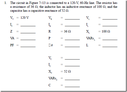
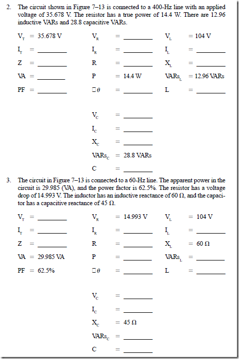
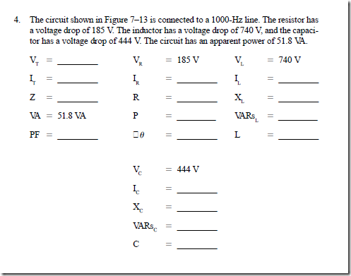
Find the missing values in the following circuits. Refer to Figure 7–13 and the formulas listed in the Resistance, Inductive, Capacitive (Series) section of Appendix 15.

image

image

image

image