Alternating-Current Generators : Hunting.

HUNTING

If the torque output of a prime mover pulsates, it may cause the rotor of the alternator to be pulled ahead of, and then behind, its normal running position. A diesel engine is one example of a prime mover that has a pulsating torque output. If an alternator is used with a diesel engine, the alternator rotor periodically will move slightly faster and then slower. This pulsating or oscillating effect is called hunting. It causes the current to surge back and forth between alternators operating in parallel. This condition is unsatisfactory and may become cumulative, resulting in such a large increase in the current between the alternators that the overload relays open the circuit.

Hunting can be corrected by the use of a heavy flywheel. A damper winding is often used in the rotating field structure to minimize the pulsating torque. Figure 12–2 showed a damper winding, which is often called an amortisseur winding. This winding is embedded in slots in each of the pole faces of the rotating field. The amortisseur winding consists of heavy conductors that are brazed or welded to two end rings. At the instant that hunting develops, the path of the armature flux changes so that it cuts the short-circuited conductors of the amortissuer winding. This change in the flux path produces induced currents in the damper winding. The currents oppose the force producing them (by Lenz’s law). The proper design of the damper winding ensures that the effects of hunting are canceled by the induced currents in the short-circuited conductors.

SUMMARY

• An emf is generated

1. when there is relative motion between the armature conductors and the field.

2. in armature conductors when rotating in a magnetic field with stationary field poles.

3. in stationary armature conductors when the field poles rotate past the conductors.

• A dc generator has stationary field poles and rotating armature conductors. The alternating voltage induced in the rotating armature conductors is changed to a direct voltage at the brushes by means of the commutator.

• AC generators (alternators) do not use commutators.

• Alternators are classified into two groups:

1. Revolving armature machines with stationary fields; the kilovolt-ampere capacity and the low-voltage rating of these machines are usually rather small.

2. Revolving field machines with stationary armature (stator) conductors.

a. The field poles rotate inside the stator.

b. Higher voltages can be generated without insulation failure.

c. Higher current values can be obtained without arcing or heat production at the brushes and slip rings.

• There are two types of revolving fields:

1. The salient field rotor (used with slow-speed alternators up to 1800 r/min).

2. The cylindrical field rotor (used for speeds from 1800 to 3600 r/min; most steam turbine-driven alternators have cylindrical rotors).

• An ac generator cannot supply its own field current:

1. The field excitation is direct current and is supplied from an external direct-current source.

2. Slip rings and brushes are used to take the excitation current from the external source to the field windings.

3. The field voltage is usually in the range between 100 and 250 V.

4. The amount of power delivered to the field circuit is relatively small.

• The induced field voltage is large enough to damage equipment. To eliminate this dan- ger, a special field discharge switch is used.

1. In the closed position, the field discharge switch acts like a normal double-pole, single-throw switch.

2. When the switch is opened, an auxiliary blade closes just before the main switch blades open.

3. When the main switch blades are fully open, a circuit path still exists through the auxiliary switch blade.

4. This path goes through the field discharge resistor, bypassing the field rheostat and the ammeter.

5. The voltage induced in the field coils by the collapsing magnetic field dissipates quickly as a current through the field discharge resistor.

6. A large machine may use a field contactor or field circuit breaker for the same purpose; each of these devices has two normally open main poles and one over- lapping normally closed discharge pole.

• Large three-phase, revolving field-type ac generators can use one of several types of stationary armature (stator) windings; these windings generally consist of an even number of coils spaced around the perimeter of the stator core.

1. The formed coil is machine wound and insulated before it is installed in the slots of the stator core.

2. A full-pitch coil spans the distance between poles of opposite polarity.

3. A fractional-pitch coil is smaller than the distance between poles of opposite polarity. All of the coils of one single-phase winding are known as a phase belt.

a. Connecting the formed coils of a phase belt (single-phase winding) in series yields a maximum voltage.

b. Reconnecting the same coils in parallel yields the maximum current possible at a lower voltage value.

4. A three-phase alternator has three separate windings that are placed in the slots of the stator core.

a. The windings are arranged so that three voltages are produced and are 120 electrical degrees apart.

b. The three single-phase windings (phase belts) may be connected in either delta or wye.

c. The wye connection is more commonly used because it gives a higher terminal voltage: 1.73 times the phase winding voltage.

• Eddy currents in the stator core due to the flux of the revolving field can be reduced by the use of a laminated core. Such a core consists of thin strips of steel clamped together.

• Ventilating ducts in the core of the stator and ventilating passages in the steel frame prevent the temperature of the stator windings from becoming too high.

1. When the alternator has a salient field rotor, it acts as a fan to aid cooling.

2. High-speed alternators with cylindrical rotors normally have a cooling system that completely encloses the alternator. Either air or hydrogen is used in the system. Hydrogen is more efficient than air because it has almost seven times the heat conductivity of air. However, hydrogen is explosive and is costly to replace.

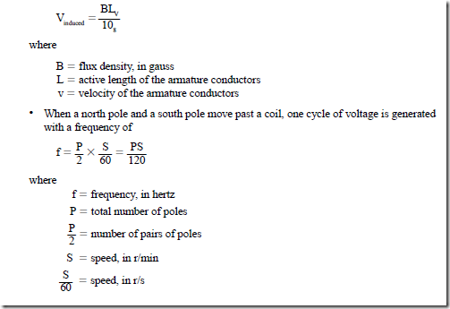
• When an armature conductor of a generator is cut by a rotating magnetic field, the induced voltage is

image

• Controlling the field current:

1. The voltage induced in any alternator depends on the field strength and the speed of the rotor.

2. To maintain a fixed frequency, an alternator must operate at a constant speed.

3. The magnitude of the generated voltage depends on the dc field excitation.

4. The following method can be used to change or control the terminal voltage:

a. A rheostat is connected in series with the separately excited field circuit.

b. If an alternator is operated at a constant speed with a fixed field excitation cur- rent, the terminal voltage will change with an increase in the load current.

c. The actual change in voltage is influenced by the power factor of the load circuit and the impedance of the armature windings.

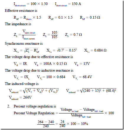
• Percent voltage regulation is the change in the terminal voltage from a full-load to a no-load condition at a constant speed and a fixed field excitation current:

image

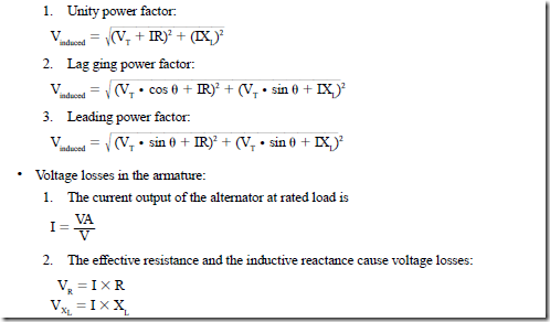
• Vector diagrams can be used to determine the induced voltage of an alternator for different load power factors:

image

• At a lagging power factor, the induced voltage is greater than when the load power factor was unity.

• At a leading power factor, the induced voltage is less than when the load power factor was unity. In this case, the induced voltage is less than the terminal voltage.

• Synchronous reactance:

1. The voltage drop due to the inductive reactance and the armature reaction have the same effect on the terminal voltage.

2. Both of these effects are proportional to the armature current.

3. These two effects are known as the synchronous reactance, X .

The synchronous impedance test is used to determine values of R and XLS

1. In this test, the field excitation current and the alternator speed are kept at constant values.

2. The line terminals of the alternator are shorted through an ammeter when the test switch is closed.

3. The field excitation current increases until the current in the armature is nearly 150% of the rated full-load current. This value of current is recorded.

4. The test switch is opened and the reading of a voltmeter connected across the generator terminal is recorded.

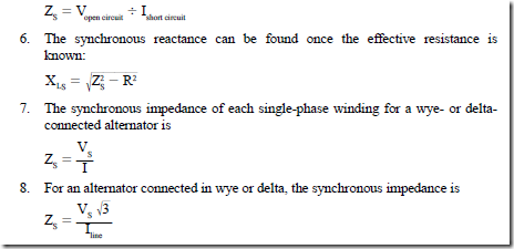
5. The synchronous impedance is

image

• A relatively constant alternator terminal voltage can be maintained under changing load conditions by the use of an automatic voltage regulator:

1. As the terminal voltage decreases, a relay closes contacts in the regulator to short out a field resistor. There is a resulting increase in the field current, field flux, and induced voltage.

2. An increase in the terminal voltage causes the relay to open the contacts across the field resistor. This action causes a decrease in the field current, field flux, and induced voltage.

3. Many other types of automatic voltage regulators may be used with alternators.

These regulators may use vacuum tubes, amplidynes, magnetic amplifiers, ignition rectifiers, controlled silicon rectifiers, or solid-state control devices.

• Saturation point:

1. For a constant-speed generator, the generated voltage is a direct function of the flux value per pole.

2. The flux is determined by the number of ampere-turns of the field pole. Because the number of turns on each field winding is constant, the flux is proportional to the dc excitation.

3. Increasing the dc excitation increases the flux; therefore, the induced voltage also increases.

4. A point is reached at which the flux no longer increases in proportion to the increase in dc excitation. This point is called the saturation point.

• Reading the saturation curve:

1. The saturation curve shows an increase in induced voltage with an increase in the field current in an alternator.

2. The ascending curve shows an increase in induced voltage as the field current is increased; the descending curve represents a decrease in induced voltage as the field current is decreased.

3. The first part of the ascending curve is nearly vertical because the induced voltage is almost directly proportional to the increase in field current.

4. When the alternator is being driven and the field current is zero, there is a small induced voltage. This voltage is due to the effects of residual magnetism after the magnetomotive force is removed from the field.

5. As the ascending curve reaches the saturation point, it flattens out. From this point to the maximum induced voltage on the curve, the increase in induced voltage is not proportional to the increase in field current.

6. The knee of the ascending curve is located immediately before and after the saturation point.

7. After reaching the maximum induced voltage, the field current is decreased to zero. The resulting plot of these events is the descending curve.

8. Note that the descending curve has a slightly higher induced voltage than does the ascending curve. This reaction is due to molecular friction or hysteresis effects in which the molecules of the iron in the magnetic circuit stay aligned even after the magnetomotive force is decreased.

9. The operating point of a particular generator occurs near the center of the knee of the ascending curve. At this point, there is a maximum ac voltage output with minimal I2 R losses in the field circuit.

• The alternator nameplate contains the following data:

1. The capacity of the alternator, in kVA

2. The full-load terminal voltage

3. The rated full-load current per terminal

4. The number of phases

5. The frequency

6. The speed in r/min

7. The operating power factor

8. The dc field current and voltage

9. The maximum temperature rise

• Power losses in an alternator consist of fixed or stray losses such as

1. the bearing and brush friction losses.

2. windage losses.

3. iron losses, including eddy current and hysteresis losses.

4. copper losses, including the I2 R losses in the armature windings and the power expended in the separately excited field circuit.

• Alternator efficiency:

image

2. An alternator should be operated at or near the rated full-load output to obtain the maximum efficiency.

3. Alternators with capacities in the order of 200,000 kVA may have efficiency ratings as high as 96% at the full-load output.

• Advantages of paralleling alternators:

1. They aid in scheduling of maintenance and emergency repairs on alternators.

2. They allow the alternators on the line to be operated near their full-load rating (high efficiency range). Another alternator may be paralleled with the first one to meet peak demands.

3. The generating plant capacity may be expanded to meet increased power demands by installing more alternators. These machines then operate in parallel with the existing generating equipment.

• To parallel ac generators:

1. Observe the following conditions:

a. The output voltages of the alternators must be equal.

b. The frequencies of the alternators must be the same.

c. The output voltages of the alternators must be in phase.

2. If these three conditions are met, the alternators are said to be in synchronism.

• Synchronizing two alternators:

1. Three-lamp method

a. The three lamps go on and off in unison depending on the frequency difference between the two alternators.

(1) For this case, a slight adjustment in the speed of the prime mover for the alternator coming on line will make the frequency of this machine the same as the alternator presently on the line.

(2) When all three lights go out, the instantaneous electrical polarity of the second machine will equal that of the alternator on the line. The second machine can be brought on line, and the generators will be paralleled.

b. The three lamps will light and go off, but not in unison. In this case, the phase sequence or phase rotation of the second generator is not the same as the alternator on the line. By interchanging the connections of any two leads of the second alternator, the phase sequence can be changed. The steps in part 1 can be followed to adjust the frequency of the second machine so that it can be paralleled.

2. Three lamps dark method

a. This method is used to determine the phase sequence of an alternator.

b. Once the phase sequence is known, permanent connections can be made between the stator windings, the switching equipment, and the station bus bars. It is not necessary to determine the phase sequence each time the alter- nator is paralleled once the equipment is marked correctly.

c. This method is also used to indicate when alternators are in synchronism.

3. Two bright, one dark method:

a. This method is never used to determine the phase sequence.

b. It is used to indicate the synchronism of two alternators.

c. When the incoming alternator is in synchronism (ready to be paralleled), two lamps in lines 1 and 2 will have a maximum brightness and the lamp in line 3 will be dark.

4. There are disadvantages to both methods of testing:

a. There may be a large voltage difference across the synchronizing lamps (even when they are dark); thus, a large voltage difference and phase difference may be present.

b. When an attempt is made to bring the incoming alternator into the bus bar circuit system with the other machines, a large disturbance in the electrical system may result in damage to the alternator windings.

• Use of the synchroscope:

1. Once the phase sequence is known to be correct and permanent connections are made, a synchroscope can be used.

2. The single-phase synchroscope indicates synchronism accurately.

3. A synchroscope gives an accurate indication of the differences in the frequency– phase relationship between two voltages.

a. A pointer rotates over a dial face. When the pointer stops, the frequencies of the two alternators are the same.

b. When the pointer stops in a vertical upward position, the frequencies are equal and the voltages are in phase. This means that the alternators are in syn- chronism and the alternator switch can be closed to parallel both machines.

• Once the two alternators are operating in parallel, the load is shared between them.

1. The load taken by each machine is proportional to the kVA rating of the machine.

2. Changing the field excitation of each dc generator will divide the load between the generators connected in parallel. The same method cannot be used to divide the kilowatt load between the two alternators in parallel.

3. A different method is used to divide the load between two alternators.

a. The prime movers for such alternators should have drooping speed–load characteristic curves.

b. To divide the load equally between the two machines, the input to the prime mover must be increased. The governor on the prime mover of the light-load alternator is opened slightly. As a result, there is an increase in both the horse- power of the light-load alternator and the power output of the alternator. At the same time, the governor on the prime mover of the heavy-load alternator is closed very slightly. This action causes decreases in the input to the prime mover, the horsepower input to the heavy-load alternator, and the power out- put (in kW) of the same alternator.

c. Careful adjustment of the governors of both prime movers can result in the speed–load characteristic curve of each cutting the system frequency line at the same load point. Thus, there is a satisfactory load division between the machines.

d. This adjustment of the prime movers must be obtained without causing a change in the frequency.

• When alternators are operating in parallel, a faulty governor may cause the speed of an alternator to increase; thus, the machine may be pulled out of synchronism.

1. Certain reactions within the alternator will prevent this condition.

2. If the governor malfunctions so that it cuts out completely and shuts off the input to the prime mover, the alternator will operate as a synchronous motor until the governor fault is corrected.

• Hunting

1. is a pulsating or oscillating effect.

2. of the prime mover causes a torque that may cause the rotor of the alternator to be pulled ahead of, and then behind, its normal running position.

3. causes the current to surge back and forth between alternators operating in parallel; this condition is unsatisfactory and may become cumulative, resulting in the circuit being opened by the overload relays.

4. can be corrected by using

a. a heavy flywheel.

b. a damper winding in the rotating field structure. Such a winding is often called an amortisseur winding. The proper design of this winding ensures that the effects of hunting are canceled by the induced currents in the short- circuited conductors.

Achievement Review

1. List two advantages of the rotating field alternator, as compared with the rotating armature ac generator.

2.

a.

b.

Where is the salient pole rotor used? Where is the cylindrical rotor used?

3.

a.

Explain why a field discharge resistor is used with the separately excited field circuit.

b.

Draw a schematic wiring diagram of a separately excited field circuit of an alternator. Include a field discharge switch, a field discharge resistor, an ammeter, and a field rheostat. Connect the circuit so that the field rheostat and the ammeter are not in the field discharge circuit path.

4.

a.

What methods are used to cool the windings of a high-speed turbine-driven alternator having a large kVA capacity?

b.

There are fewer problems in cooling the windings of slow-speed alternators using salient pole rotors. Why?

5.

A

25-kVA, 250-V, 60-Hz, 1800-r/min, single-phase alternator has an

armature resistance of 0.12 W and an armature reactance of 0.5 W. The generator delivers the rated load output at a power factor of 1.00 (unity) to a non- inductive load. Determine the induced voltage. (Neglect any armature reaction.)

6. a. Determine the induced voltage of the alternator in question 5 when it delivers the rated output to a load with a lagging power factor of 0.8660.

b. Determine the induced voltage of the alternator in question 5 when it delivers the rated output to a load with a leading power factor of 0.8660.

7. a. Define voltage regulation as it is used with alternators.

b. The full-load terminal voltage of an alternator is 240 V. The load is removed.

The no-load terminal voltage increases to 265 V at the same speed and field excitation. What is the percent voltage regulation of the alternator?

8. A three-phase, wye-connected alternator is rated at 2000 kVA, 4800 V, 60 Hz. In a short-circuit synchronous impedance test, the field excitation current is increased until the three line ammeters indicate nearly 150% of 360 A, the rated line cur- rent. The field excitation current and the speed are kept constant and the three-pole switch is opened. The voltmeter indicates 2250 V. The dc resistance between the line terminals is 0.4 W, and the ratio of effective to ohmic resistance is 1.5. Determine

a. the synchronous impedance.

b. the effective resistance.

c. the synchronous reactance.

9. Determine the no-load voltage and the percent voltage regulation for the alterna- tor in question 8. Assume that the alternator is delivering the rated current to a noninductive, unity power factor load.

10. a. Determine the no-load voltage and the percent voltage regulation for the alter- nator in question 8 assuming that it is delivering the rated current to a load with a lagging power factor of 0.8.

b. Find the no-load voltage and the percent voltage regulation for the same alter- nator when it delivers the rated current to a load with a leading power factor of 0.8.

11. Explain what is meant by the terms

a. synchronous reactance.

b. synchronous impedance.

12. a. Draw a typical saturation curve for an alternator.

b. Give two reasons why saturation curves are used.

13. a. What are the fixed losses of an alternator?

b. What are the copper losses of an alternator?

c. How is the full-load efficiency of an alternator determined?

14. A three-phase, wye-connected alternator is rated at 500 kVA, 2400 V, 60 Hz.

Determine

a. the full-load kilowatt output of the generator at 80% lagging power factor.

b. the full-load current per line terminal for the alternator.

c. the full current rating of each of the phase windings.

d. the voltage rating of each of the phase windings.

15. A three-phase, delta-connected, diesel-driven alternator is rated at 50 kVA, 240 V, 60 Hz.

a. Determine

(1) the full-load current rating per line terminal for the alternator.

(2) the full-load current rating of each of the phase windings.

(3) the voltage rating of each of the phase windings.

b. If the alternator has a rated speed of 240 r/min, how many poles are required for the rotating field?

16. A 5-kVA, 208-V, three-phase alternator is connected in wye.

a. Determine

(1) the line current per terminal at full load.

(2) the coil current at full load.

(3) the voltage of each phase winding.

b. Assuming that this alternator is reconnected in delta, compute the new terminal voltage and the current at full load.

17. A three-phase, 60-Hz, wye-connected turbine-driven alternator has three single- phase windings. Each winding is at 8000 V and 625 A. The alternator has four poles. Determine

a. the kilovolt-ampere rating of the alternator.

b. the kilowatt output of the alternator when it delivers the rated current to a load with an 80% lagging power factor.

c. the line voltage.

d. the rated full-load line current.

e. the speed in r/min of the revolving field of the alternator.

18. For the turbine-driven, high-speed alternator described in question 17, answer the following questions:

a. Why is the field, rather than the armature, the rotating member?

b. Why is a cylindrical rotating field used, rather than one with salient poles?

c. How is the dc excitation current supplied to the rotor of the rotating field alternator?

19. List three reasons why ac generators are operated in parallel.

20. A three-phase, wye-connected alternator is rated at 10,000 kVA, 11,000 V, and 60 Hz. Determine

a. the full-load kilowatt output of the ac generator at a lagging power factor of 80%.

b. the full-load line current of the alternator.

c. the voltage rating of each of the three windings.

d. the horsepower input to the alternator when it delivers the rated load output at an efficiency of 92% and a lagging power factor of 80%.

21. A 240-V, single-phase, 60-Hz, revolving field alternator delivers 30 kW to a non- inductive load. The generator efficiency is 86%, and the stray power losses are 2000 W. The separately excited field requires 6 A at 240 V, dc. Determine

a. the full-load current.

b. the copper losses in the stator winding.

22. a. List the steps, in chronological order, required to place a three-phase alterna- tor in parallel with another ac generator. Assume that this is the first time that the alternator is placed in service.

b. After paralleling the alternators, what means are used to redistribute the kilo- watt load between the two alternators? Assume that the frequency is held constant.

23. a. Diagram the “three lamps dark” method of synchronizing an alternator to the bus bars.

b. How is this method used to determine whether the phase sequence of an alternator is correct with reference to the station bus bars?

24. a. Diagram the “two lamps bright, one lamp dark” method.

b. How is this method used to determine when an incoming alternator is in phase with the bus bars?

25. a. What does the term hunting mean as applied to slow-speed alternators?

b. How does the amortisseur or damping winding on the field rotor decrease the effects of hunting?

c. What other way is used to minimize the effects of hunting?

26. Explain how equal load distribution is obtained between alternators in parallel.

27. Explain what happens when an attempt is made to shift the kilowatt load between alternators by changing the field excitation. Assume that the input to the prime movers of the alternators is not changed.

List the data commonly found on the nameplate of an alternator.


Alternating-Current Generators : Synchronous impedance (with armature reaction)

SYNCHRONOUS IMPEDANCE (WITH ARMATURE REACTION)

Values of R and X are usually not given for alternators. A method known as the synchronous impedance test can be employed to determine these values. A single-phase alternator is shown in Figure 12–23. To perform this test, the output terminals of the alternator will be shorted by switch S. An ammeter is connected in the alternator circuit to indicate current and a voltmeter is connected across the output terminals to measure voltage.

image

For discussion purposes, assume that switch S is closed. The field excitation current will be increased until the output current is 150% of the rated full-load current of the alternator. This value of current is recorded. Switch S is then opened and the voltage across the output terminals is recorded. The field excitation current and alternator speed are kept constant. To determine the synchronous impedance of the alternator, the voltage for an open-circuit condition is divided by the current for a short-circuit condition. When the winding is shorted, the voltage is expended in the armature or stator winding. The voltage maintains the current through the impedance of the windings at the operating frequency. The synchronous impedance formula is

image

PROBLEM 1

Statement of the Problem

The connection in Figure 12–23 is used to determine the synchronous impedance of a 24-kVA, 240-V, single-phase 60-Hz alternator. The field excitation is adjusted until the ammeter indicates 150% of the rated full-load current. At the same values of field excitation current and speed, switch S is opened. The voltmeter indicates 105 V. The ohmic resistance of the armature or stator winding is measured at 0.1 D. It will also be necessary to assume an effective resistance value for the alternator. Recall that the effective resistance value in an ac circuit can be greater than the measured ohmic value. This is due to factors such as skin effect, eddy current induction into the iron core of the stator winding, and hysteresis losses. Because the windings are inserted deep in slots formed in the core material, the effective resistance could be high. For this example, it will be assumed that the effective resistance will be 1.5 times greater than the measure resistance value.
At unity power factor, determine

1. the induced voltage when the alternator is delivering the rated current.

2. the percent voltage regulation.

Solution

image

image

Synchronous Impedance of a Wye-Connected Alternator

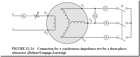
The voltage regulation of a three-phase alternator can also be determined using the synchronous impedance method. Figure 12–24 shows the circuit used to determine the synchronous impedance of a wye-connected ac generator. By closing the three-pole shorting switch (S), the field excitation current is increased gradually until the ammeters indicate 150% of the rated output current. The three ammeter readings are recorded. The three-pole switch is then opened and the voltmeter reading is recorded. The field excitation current and speed are kept constant for both readings. Because the alternator is connected in wye, the voltage of each phase winding is equal to the open-circuit voltage across the line terminals divided by the J3.

The ammeters connected in the lines indicate the phase current values because line current and phase current are the same in a wye connection. The formula for determining the synchronous impedance of each phase winding is

image

image

The following problem shows how to determine the voltage regulation of a wye-connected alternator.

PROBLEM 2

Statement of the Problem

A 2100-kVA, 2400-V, three-phase, wye-connected alternator is short-circuited using three ammeters, as shown in Figure 12–24. A voltmeter is connected across two of the line terminals. The field excitation current is increased until each of the three ammeters indicates 150% of the rated full-load current. The switch is opened and the voltmeter indicates an open circuit voltage of 1125 V. The field excitation current and speed are kept constant for both readings. The ohmic resistance is measured at 0.2 D between the line terminals. The ratio of effective resistance to the ohmic resistance is 1.5. Determine

1. the full-load current.

2. the current value for the test.

3. the synchronous impedance.

4. the effective resistance.

5. the synchronous reactance.

6. the voltage regulation at unity power factor.

7. the voltage regulation at 0.866 lagging power factor.

8. the voltage regulation at 0.866 leading power factor.

Solution

1. Full-load current:

image

3. Synchronous impedance:

image

4. Effective resistance – the measured value of 0.2 D is the resistance of two separate phase windings connected in series. Therefore, the resistance of one phase winding is one-half the measured value.

image

The vector diagram of Figure 12–25 includes the effects of the armature reactance and the armature reaction for an alternator with a unity power factor load. Note the similarity of this vector diagram with the one given in Figure 12–18. Only the armature impedance, reactance, and the effective resistance were considered.

image

7. Voltage regulation at 0.866 lagging power factor:

image

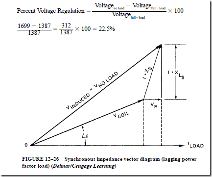
Regardless of the power factor, the full-load current is the same. Therefore, for any power factor load conditions, the voltage loss due to the effective resistance and inductive reactance of the armature or stator winding will be the same. However, the calculated value of the voltage at no load will be different from the value for a unity power factor load. Figure 12–26 and the following calculations show why the voltage at no load is much higher than the voltage at full load with a lagging power factor. This situation means that there is poorer voltage regulation.

To determine the induced voltage at a power factor of 86.6%, or 0.866, it is necessary to determine angle theta. Power factor is the cosine of angle theta. Therefore, angle theta is 30°.

image

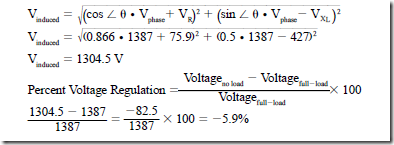
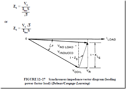
A vector diagram is given in Figure 12–27 for an alternator supplying a load with a leading power factor of 86.6%, or 0.866. In some cases, the voltage at no load may be less than the voltage at full load, depending on the amount of voltage drop due to effective resistance and the voltage drop due to inductive reactance. As a result, a negative value is obtained for the percent voltage regulation. Whenever the percent voltage regulation is negative, the voltage at no load is less than the voltage at full load. In this case, the voltage at no load (V induced) is less than the voltage at full load. Note that in this formula, the voltage drop due to inductive reactance is subtracted from the phase voltage instead of being added to the phase voltage.

image

Determining Regulation of Three-Phase, Delta-Connected Generator

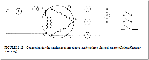
The synchronous impedance test can also be used to find the voltage regulation of a three-phase, delta-connected alternator (Figure 12–28). For a delta connection, the line cur- rent is equal to the phase winding current, multiplied by √-3. In addition, the phase winding voltage and the line voltage are equal. Therefore, the synchronous impedance of each phase winding for a generator connected in delta is

image

image

The voltage regulation is to be found for the alternator in the following example. This is the same alternator described in previous examples, except that the phase windings are connected in delta. It is assumed that each phase winding has the following full-load rating: coil current = 289 A and coil voltage = 1387 V.

If each phase winding is loaded to 150% of its rated value, then the coil current is 289 × 1.5 = 433.5 A.

The three-phase windings are connected in delta. Therefore, the line current for a short-circuit condition is 433.5 × J3 = 750 A.

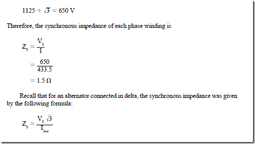
The open-circuit voltage per phase winding is the same for both the wye and delta connections:

image

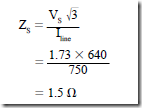
This same formula can be used to find the synchronous impedance of an alternator connected in wye:

image

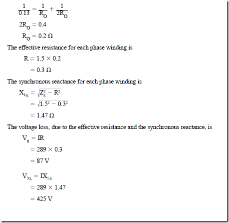
When the ohmic resistance of a delta-connected armature winding is measured across any pair of line terminals, the resulting value includes the resistance of one phase winding in parallel with the other two windings connected in series. For example, when the alternator is connected in wye, the ohmic resistance of each phase winding is 0.2 D. If the three windings are connected in delta, then the ohmic resistance is 0.133 D measured across any pair of line terminals. For both the delta and wye connections, the ohmic resistance of each phase winding is 0.2 D:

image

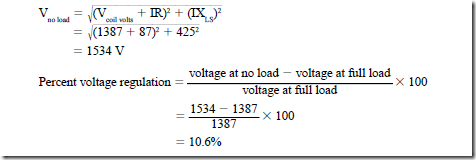
The same procedures are used to determine the voltage at no load and the percent voltage regulation for both delta- and wye-connected alternators. The following calculations give the percent voltage regulation for a delta-connected alternator with a unity power factor load; note that the results are the same as those obtained when the phase windings were connected in wye:

image


Alternating-Current Generators : Synchronous impedance (with armature reaction)

SYNCHRONOUS IMPEDANCE (WITH ARMATURE REACTION)

Values of R and X are usually not given for alternators. A method known as the synchronous impedance test can be employed to determine these values. A single-phase alternator is shown in Figure 12–23. To perform this test, the output terminals of the alternator will be shorted by switch S. An ammeter is connected in the alternator circuit to indicate current and a voltmeter is connected across the output terminals to measure voltage.

image

For discussion purposes, assume that switch S is closed. The field excitation current will be increased until the output current is 150% of the rated full-load current of the alternator. This value of current is recorded. Switch S is then opened and the voltage across the output terminals is recorded. The field excitation current and alternator speed are kept constant. To determine the synchronous impedance of the alternator, the voltage for an open-circuit condition is divided by the current for a short-circuit condition. When the winding is shorted, the voltage is expended in the armature or stator winding. The voltage maintains the current through the impedance of the windings at the operating frequency. The synchronous impedance formula is

image

PROBLEM 1

Statement of the Problem

The connection in Figure 12–23 is used to determine the synchronous impedance of a 24-kVA, 240-V, single-phase 60-Hz alternator. The field excitation is adjusted until the ammeter indicates 150% of the rated full-load current. At the same values of field excitation current and speed, switch S is opened. The voltmeter indicates 105 V. The ohmic resistance of the armature or stator winding is measured at 0.1 D. It will also be necessary to assume an effective resistance value for the alternator. Recall that the effective resistance value in an ac circuit can be greater than the measured ohmic value. This is due to factors such as skin effect, eddy current induction into the iron core of the stator winding, and hysteresis losses. Because the windings are inserted deep in slots formed in the core material, the effective resistance could be high. For this example, it will be assumed that the effective resistance will be 1.5 times greater than the measure resistance value.

At unity power factor, determine

1. the induced voltage when the alternator is delivering the rated current.

2. the percent voltage regulation.

Solution

image

image

Synchronous Impedance of a Wye-Connected Alternator

The voltage regulation of a three-phase alternator can also be determined using the synchronous impedance method. Figure 12–24 shows the circuit used to determine the synchronous impedance of a wye-connected ac generator. By closing the three-pole shorting switch (S), the field excitation current is increased gradually until the ammeters indicate 150% of the rated output current. The three ammeter readings are recorded. The three-pole switch is then opened and the voltmeter reading is recorded. The field excitation current and speed are kept constant for both readings. Because the alternator is connected in wye, the voltage of each phase winding is equal to the open-circuit voltage across the line terminals divided by the J3.

The ammeters connected in the lines indicate the phase current values because line current and phase current are the same in a wye connection. The formula for determining the synchronous impedance of each phase winding is

image

image

The following problem shows how to determine the voltage regulation of a wye-connected alternator.

PROBLEM 2

Statement of the Problem

A 2100-kVA, 2400-V, three-phase, wye-connected alternator is short-circuited using three ammeters, as shown in Figure 12–24. A voltmeter is connected across two of the line terminals. The field excitation current is increased until each of the three ammeters indicates 150% of the rated full-load current. The switch is opened and the voltmeter indicates an open circuit voltage of 1125 V. The field excitation current and speed are kept constant for both readings. The ohmic resistance is measured at 0.2 D between the line terminals. The ratio of effective resistance to the ohmic resistance is 1.5. Determine

1. the full-load current.

2. the current value for the test.

3. the synchronous impedance.

4. the effective resistance.

5. the synchronous reactance.

6. the voltage regulation at unity power factor.

7. the voltage regulation at 0.866 lagging power factor.

8. the voltage regulation at 0.866 leading power factor.

Solution

1. Full-load current:

image

3. Synchronous impedance:

image

4. Effective resistance – the measured value of 0.2 D is the resistance of two separate phase windings connected in series. Therefore, the resistance of one phase winding is one-half the measured value.

image

The vector diagram of Figure 12–25 includes the effects of the armature reactance and the armature reaction for an alternator with a unity power factor load. Note the similarity of this vector diagram with the one given in Figure 12–18. Only the armature impedance, reactance, and the effective resistance were considered.

image

7. Voltage regulation at 0.866 lagging power factor:

image

Regardless of the power factor, the full-load current is the same. Therefore, for any power factor load conditions, the voltage loss due to the effective resistance and inductive reactance of the armature or stator winding will be the same. However, the calculated value of the voltage at no load will be different from the value for a unity power factor load. Figure 12–26 and the following calculations show why the voltage at no load is much higher than the voltage at full load with a lagging power factor. This situation means that there is poorer voltage regulation.

To determine the induced voltage at a power factor of 86.6%, or 0.866, it is necessary to determine angle theta. Power factor is the cosine of angle theta. Therefore, angle theta is 30°.

image

A vector diagram is given in Figure 12–27 for an alternator supplying a load with a leading power factor of 86.6%, or 0.866. In some cases, the voltage at no load may be less than the voltage at full load, depending on the amount of voltage drop due to effective resistance and the voltage drop due to inductive reactance. As a result, a negative value is obtained for the percent voltage regulation. Whenever the percent voltage regulation is negative, the voltage at no load is less than the voltage at full load. In this case, the voltage at no load (V induced) is less than the voltage at full load. Note that in this formula, the voltage drop due to inductive reactance is subtracted from the phase voltage instead of being added to the phase voltage.

image

Determining Regulation of Three-Phase, Delta-Connected Generator

The synchronous impedance test can also be used to find the voltage regulation of a three-phase, delta-connected alternator (Figure 12–28). For a delta connection, the line cur- rent is equal to the phase winding current, multiplied by √-3. In addition, the phase winding voltage and the line voltage are equal. Therefore, the synchronous impedance of each phase winding for a generator connected in delta is

image

image

The voltage regulation is to be found for the alternator in the following example. This is the same alternator described in previous examples, except that the phase windings are connected in delta. It is assumed that each phase winding has the following full-load rating: coil current = 289 A and coil voltage = 1387 V.

If each phase winding is loaded to 150% of its rated value, then the coil current is 289 × 1.5 = 433.5 A.

The three-phase windings are connected in delta. Therefore, the line current for a short-circuit condition is 433.5 × J3 = 750 A.

The open-circuit voltage per phase winding is the same for both the wye and delta connections:

image

This same formula can be used to find the synchronous impedance of an alternator connected in wye:

image

When the ohmic resistance of a delta-connected armature winding is measured across any pair of line terminals, the resulting value includes the resistance of one phase winding in parallel with the other two windings connected in series. For example, when the alternator is connected in wye, the ohmic resistance of each phase winding is 0.2 D. If the three windings are connected in delta, then the ohmic resistance is 0.133 D measured across any pair of line terminals. For both the delta and wye connections, the ohmic resistance of each phase winding is 0.2 D:

image

The same procedures are used to determine the voltage at no load and the percent voltage regulation for both delta- and wye-connected alternators. The following calculations give the percent voltage regulation for a delta-connected alternator with a unity power factor load; note that the results are the same as those obtained when the phase windings were connected in wye:

image


Alternating-Current Generators : Armature voltage losses (neglecting armature reaction).

ARMATURE VOLTAGE LOSSES (NEGLECTING ARMATURE REACTION)

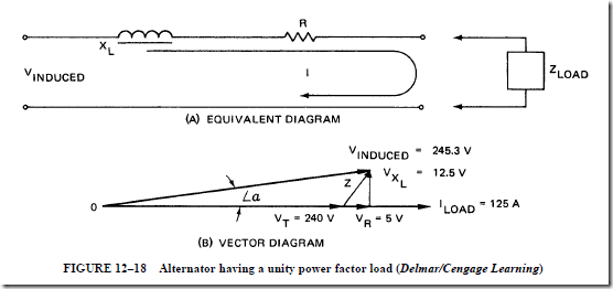
All alternator armatures have coils and generate ac voltages. Thus, the equivalent diagrams of such alternators must show a resistor and an inductor (Figure 12–18A).

The equivalent diagram in this case is a series RL circuit. This means that a series circuit analysis can be made to solve for the required quantities.

The vector equation is

image

Unity Power Factor

For resistive loads, V and IR are in phase with the reference current I. IX is 90° out of phase with I. The resulting vector diagram is shown in Figure 12–18B. The effects that resistive loads have on the terminal alternator voltage are illustrated in the following example.

A single-phase, 60-Hz alternator has a full-load rating of 30 kVA at 240 V. The armature windings have an effective resistance of 0.04 D and an inductive reactance of 0.1 D. What is the induced voltage in the alternator windings when the full-load current is delivered at a load power factor of unity?

The current output of the alternator at rated load is

image

The vector diagram shows that the induced voltage is the hypotenuse of a right triangle. Thus

image

The voltage at the terminals of the generator is 240 V and is in phase with the load current. At the same time, the induced voltage in the armature is 245.3 V. The load current lags the induced voltage by the angle rr.

Lagging Power Factor

Figure 12–19 is a vector diagram for the same 30-kVA alternator described in the previous example. In this case, however, the power factor load is lagging. The alternator delivers the rated load current of 125 A at a terminal voltage of 240 V to a load with a 0.8 lagging power factor. The load current lags the terminal voltage by the angle e. In this example, e equals 37°. In the diagram, the 5-V IR drop in the armature windings is placed at the end of the terminal voltage. Its position is such that it is in phase with the load current. A voltage loss also occurs because of the inductive reactance of the armature windings. This loss leads the load current by 90°. The resultant of IR and IXL is the armature impedance voltage drop IZ. This value is added vectorially to the terminal voltage to obtain the induced voltage in the armature. Refer to the vector

image

diagram and note that the small armature impedance triangle shifts in a clockwise direction when the current lags the terminal voltage. This shift means that the induced voltage vector has a greater magnitude than it does for the unity power factor load in the previous example.

The induced voltage for a 0.8 lagging power factor (Figure 12–19) can be obtained using the formula

image

With the lagging power factor, the induced voltage is greater than in the case when the load power factor was unity. The induced voltage increased even though the imped- ance voltage in the armature is the same. If the induced voltage remains the same, then the terminal voltage decreases with an increase in the angle of lag of the load current behind the terminal voltage. The vector diagram in Figure 12–19 shows that this change in voltage output is due to the angle at which the armature impedance voltage drop subtracts vectorially from the induced voltage.

If the load current leads the terminal voltage, then the induced voltage in the armature is less than the terminal voltage.

Leading Power Factor

The vector diagram in Figure 12–20 for the same 30-kVA single-phase alternator is described in the two previous examples. The load current, however, leads the terminal volt- age by a phase angle of 37°. The phase relationship between the impedance voltage drop in the armature and the induced voltage causes the terminal voltage to be greater than the induced voltage. As the angle of lead between the load current and the terminal voltage increases, the armature impedance voltage vector moves counterclockwise. As a result, the

image

magnitude of the induced voltage vector is less for the same terminal voltage. To maintain a terminal voltage of 240 V when the alternator delivers the full-load current of 125 A at a 0.8 leading power factor, the required induced voltage is

image

The effects of the IR and IX voltage losses in the armature windings on the terminal voltage output were illustrated in Figures 12–18, 12–19, and 12–20. The last example described the case for a leading power factor. However, most alternators are used to supply a load having a lagging power factor.

Effect of Lagging Power Factor

When an alternator operates with a lagging power factor, a magnetomotive force (mmf ) is set up by the current in the armature conductors. This magnetizing force opposes the magnetomotive force of the main field and causes a decrease in the main field flux. As a result, there is a decrease in the induced voltage. The lower the value of the lagging power factor, the greater is the armature mmf that opposes and weakens the field. For the few applications where an alternator supplies a load with a leading power factor, the armature current sets up an mmf in the armature. This force aids the mmf of the main field so that the main field flux increases. The voltage of the alternator increases with an increase in the load current. The lower the value of the leading power factor, the greater is the armature mmf. This force aids the mmf of the main field, resulting in an increase in the main field flux.

Effect of Load Power Factor

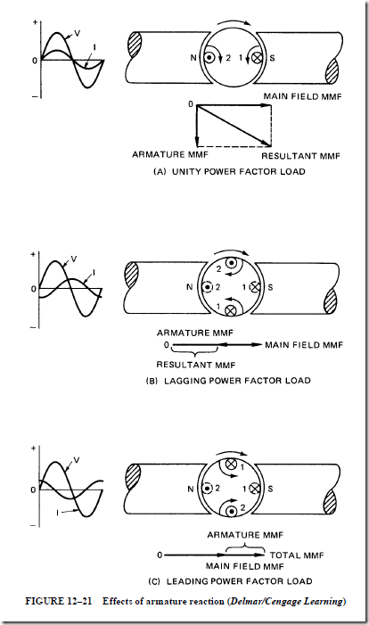
Figure 12–21 shows how the main field flux is affected by the armature mmf for different load power factors. A two-pole rotating armature-type alternator is used to simplify the illustrations. However, the same conditions occur when a revolving field-type alternator is used.

By studying Figure 12–21, it can be seen that the voltage drop due to the inductive reactance and the armature reaction have the same effect on the terminal voltage. Both of these effects are proportional to the armature current. Generally, these two effects are combined into a single quantity, called the synchronous reactance (XLS).

Slot-Type Armature Windings. The stationary armature windings of an alternator may be arranged in the slot formation shown in Figure 12–22. The armature conductors are surrounded by the laminated iron of the stator core. The eddy current losses and the hysteresis losses in the iron core structure mean that there is a loss in power. The current in the armature windings must supply the power expended in the core in overcoming the molecular friction loss (hysteresis loss) and the eddy current losses. The effective resistance will be higher than the pure ohmic resistance. Alternators rated at 25 Hz usually have an effective resistance equal to 1.2 to 1.3 times the pure ohmic resistance. Sixty-hertz generators.

image

image

have an effective resistance equal to 1.4 to 1.6 times the pure ohmic resistance. For 60-Hz alternators, the dc resistance can be measured and multiplied by 1.5 to obtain the effective resistance.


Alternating-Current Generators : The stator windings , Ventilation and Operation of a rotating field .

THE STATOR WINDINGS

It was stated earlier that the dc armature generates alternating current. If properly connected slip rings are used, instead of a commutator, both alternating voltage and current can be obtained. For a revolving armature type of single-phase alternator having a small capacity and low voltage, the armature winding generally used is the same as that of a dc generator.

Large three-phase, revolving field-type ac generators can use one of several types of stationary armature (stator) windings. These windings generally consist of an even number of coils spaced around the perimeter of the stator core.

The Formed Coil

A typical formed coil is shown in Figure 12–9. Such a coil is machine wound and insulated before it is installed in the slots of the stator core. The coil is sized so that it will span the distance between the poles of opposite polarity. A coil having this dimension is said to have full pitch. A coil smaller than this dimension is said to have fractional pitch. All of the coils of one single-phase winding are collectively known as a phase belt.

Figure 12–10 shows the formed coils of a phase belt (single-phase winding) connected in series. The resulting voltage has the maximum value possible. In Figure 12–11, the same coils are reconnected in parallel to give the maximum current possible, at a lower voltage value.

image

Three-Phase Winding

A three-phase alternator has three separate windings that are placed in the slots of the stator core. The windings are arranged so that three voltages are produced that are 120 electrical degrees apart. Figure 12–12 represents a basic form of a three-phase winding. Three separate single-phase windings are connected in wye. (The three single-phase windings, or phase belts, may be connected in either delta or wye.) The wye connection is used more often than the delta connection because a higher terminal voltage is obtained.

Figure 12–13 shows the stator winding of a three-phase alternator, using a salient pole rotor. Formed coils, similar to the one shown in Figure 12–9, are placed in the slots of the laminated stator core. These coils are connected in three single-phase windings to give three voltages 120 electrical degrees apart. The three phase belts are connected in wye to give a terminal voltage that is 1.732 times the phase winding voltage. The three terminal leads from the stator windings are brought out at the bottom of the stator core. In this location, they can be connected directly to the external three-phase circuit. The flux of the revolving field poles continuously cuts the stator core when the alternator is operating. This action produces induced voltages and the resultant eddy currents in the stator core. These eddy currents can be reduced by the use of a laminated core consisting of thin strips of steel clamped together. The laminated stator is braced with steel channels in the frame. Figure 12–13 shows a typical stator assembly. Note the ventilating ducts in the core of the stator and the ventilating passages in the steel frame. This ventilation prevents the temperature of the stator windings from becoming too high.

The slow-speed alternator shown in Figure 12–13 has a relatively large diameter. Such an alternator is suitable for use with a salient field rotor, similar to the one shown in Figure 12–2.

image


image

Stator Windings for Three-Phase Alternator

The stator core and windings shown in Figure 12–14 may be used with a turbine- driven, three-phase alternator. The stator in this case is also laminated to reduce eddy cur- rent losses. Rows of perforations are provided below the teeth of the slots on the core for the windings. These small holes serve as ventilating ducts to circulate air, or hydrogen, to reduce the heat produced in the stator core and windings.

If there is a short circuit, then the resulting short-circuit currents are great enough to stress the end connections. These current stresses can twist and tear the coil ends from the normal positions. To prevent this, special bracing is used for the coil ends, as shown in Figure 12–14.

The diameter of the stator core and windings for a turbine-driven, three-phase alternator is relatively small. The rotor that is used with the stator of Figure 12–14 is a cylindrical nonsalient type, as shown in Figure 12–1.

VENTILATION

Ventilation is not a problem in the operation of salient pole alternators. The salient poles act as fans to circulate the air. Also, large surface areas in this type of alternator are exposed to the surrounding air. Thus, heat is quickly dissipated.

image

However, high-speed alternators with cylindrical rotors do have ventilation problems. There is almost no fan effect in circulating air with the smooth cylindrical rotor. Only a limited surface area is exposed to the surrounding air in this type of alternator. The stationary armature of this alternator is relatively long, and its diameter is small. To handle the field flux, there must be enough thickness to the laminated stator core in back of the slots. This means that there must be another means of cooling such alternators. The usual method is to completely enclose the alternator with a cooling system using either air or hydrogen. Larger alternators also have hollow conductors through which oil or water can be circulated as a coolant.

Enclosed Cooling System

Most large, high-speed, turbine-driven alternators use a totally enclosed cooling sys- tem with hydrogen as the coolant. There are several reasons why hydrogen is preferred. The density of hydrogen is approximately 10% that of air. This means that the windage losses of the high-speed alternator are reduced. Hydrogen has almost seven times the heat conductivity of air. As a result, there is more effective cooling of the stator core and wind- ings. Disadvantages to the use of hydrogen are that it is explosive and costly to replace. To overcome these problems, a gastight sealing system must be used for the alternator frame. The hydrogen is circulated by a blower system through ducts in the alternator. A water- cooling system is used to cool the machine.

OPERATION OF A ROTATING FIELD

The sinusoidal field voltage shown in Figure 12–15 is induced in the conductors of a stationary armature by the flux of two poles of a rotating field structure. The stationary armature is shown on a horizontal plane. The line of travel of the field poles is also shown on a horizontal plane, moving from right to left. The relative motion between the armature and the field remains unchanged if the armature conductors are viewed as moving from left to right, with the field poles stationary. Using Fleming’s generator rule, it is assumed that the armature conductors are moving to the right in a stationary field. As a result, it can be determined that the induced voltage in armature conductor A tends to drive electrons away from the reader. At the same time, the induced voltage in conductor B causes electrons to move toward the reader. If the two conductors are connected together to make a closed coil loop, these voltages add constructively. The voltage produced depends on the flux density in gauss (B), the active length of the armature conductors (L), and the velocity (v) of the armature conductors:

image

Note that this is the same formula given earlier in Unit 1. The voltage induced in the coil loop will have a sine-wave pattern if the field poles turn at a constant speed and have a sinusoidal flux distribution.

image

As indicated in Unit 1, the frequency of the induced voltage depends on the number of poles and the speed of the ac generator. When a north pole and a south pole move past a coil, one cycle of voltage is generated. Therefore, the number of cycles of voltage generated in one revolution of the rotating field will be equal to the number of pairs of poles on the rotor. (A pair of poles means one north pole and one south pole.) The frequency of the induced voltage is expressed as follows:

image

The frequency table in Unit 1 lists the frequencies obtained for different rotor speeds and numbers of field poles.

Controlling the Field Current

The voltage induced in any alternator depends on the field strength and the speed of the rotor. To maintain a fixed frequency, an alternator must operate at a constant speed. Thus, the magnitude of the generated voltage depends on the dc field excitation. A method of changing or controlling the terminal voltage is shown in Figure 12–16.

A rheostat is connected in series with the separately excited field circuit. The three-phase voltage output of the alternator is controlled by adjusting the resistance of the rheostat. If an alternator is operated at a constant speed with a fixed field excitation current, the terminal voltage will change with an increase in the load current. The actual

image

image

change in voltage is influenced by the power factor of the load circuit and the impedance of the armature windings.

Effect of the Load Power Factor

In Figure 12–17, the graph shows the effect of the load power factor on the terminal voltage. For each load voltage characteristic curve in Figure 12–17, the alternator field rheostat was adjusted to give the same terminal voltage of 240 V when delivering the full- load current. The term percent voltage regulation is applied to the change in the terminal voltage from a full-load to a no-load condition at a constant speed and a fixed field excitation current.

Percent voltage regulation of an alternator is defined as the percentage change in terminal voltage as the load current is decreased from the full-load value to zero at constant values of speed and field excitation:

image

image


Alternating-Current Generators : Introduction Revolving armature-type alternator and Revolving field-type alternator.

Alternating-Current Generators
INTRODUCTION

It was shown in Unit 1 that an alternating voltage having a sine-wave pattern is induced in a single conductor, or armature coil, rotating in a uniform magnetic field with station- ary field poles. Similarly, an emf is generated in stationary armature conductors when the field poles rotate past the conductors. A voltage will be induced in the armature conductors whenever there is relative motion between the armature conductors and the field.

DC generators have stationary field poles and rotating armature conductors. The alter- nating voltage induced in the armature conductors is changed to a direct voltage at the brushes by means of the commutator.

AC generators are also known as alternators because they supply electrical energy with an alternating voltage. These machines do not have commutators. Therefore, the armature is not required to be the rotating member.

Alternators are classified into two groups, depending on the type of construction. One group consists of the revolving armature type of ac generator. This machine has stationary field poles and a revolving armature. The second group consists of the revolving field type of ac generator, which has a stationary armature, or stator. The field poles rotate inside the stator for this type of ac generator.

REVOLVING ARMATURE-TYPE ALTERNATOR

Figure 12–1 shows a revolving armature-type alternator. The kilovolt-ampere capacity and the low-voltage rating of such an alternator are usually rather small. This

image

machine resembles a dc generator but has slip rings rather than a commutator. An ac generator cannot supply its own field current. Thus, the field excitation is direct current and is supplied from an external direct-current source.

REVOLVING FIELD-TYPE ALTERNATOR

Revolving field alternators are used for most applications. In this type of machine, the revolving field structure (rotor) uses slip rings and brushes to take the excitation current from an external dc source. The stationary part of the generator (stator) is a laminated core. This core consists of thin steel punchings, or laminations, securely clamped together and held in place in the steel frame of the generator. The armature coils are placed in slots in the stator. The field voltage is usually in the range between 100 and 250 V. The amount of power delivered to the field circuit is relatively small.

The rotating field alternator has two advantages over the rotating armature ac generator:

1. Voltages can be generated as high as 11,000 and 13,800 V. These values can be reached because the stationary armature windings do not undergo vibration and centrifugal stresses.

2. Alternators can have relatively high current ratings. Such ratings are possible because the output of the alternator is taken directly from the stator windings through heavy, well-insulated cables to the external circuit. Neither slip rings nor a commutator are used.

The Revolving Field

Two different types of revolving field structures are commonly used. The first type to be described is the salient pole rotor. The second type of structure is known as the cylindrical rotor. The salient pole rotor has projecting field poles. It is used with alternators operating at speeds below 1800 r/min. Prime movers for such slow-speed alternators include diesel units and waterwheels. (The prime mover supplies the mechanical energy input to the generator.)

Figure 12–2 shows a salient pole rotor, which is used on a slow-speed alternator. Each pole has a laminated steel core to reduce the eddy current losses. The field coil windings are mounted on the laminated poles. The windings are connected in series to give alternate north and south polarities. The field poles are magnetized by low-voltage dc taken from an external source by two slip rings. Each field pole is bolted to the fabricated steel spider. In some cases, poles are dovetailed to the spider. This type of construction is used as a safeguard against the centrifugal force of the rotating members causing the structure to fly apart. The spider is keyed to the generator shaft. The salient pole rotor in Figure 12–2 has slots on each of the pole faces. A damper winding, also known as an amortisseur winding, is placed in each of these slots. The purpose of this winding will be described later.

Large steam turbine-driven alternators normally operate at speeds of 1800 r/min and 3600 r/min. At these speeds, large salient pole rotors are impractical. As a result, most steam turbine-driven alternators have cylindrical rotors. If a steam turbine-driven alternator is rated at less than 5000 kW, then frequently this machine is a 1200-r/min salient pole type. A speed reduction gear is used with this machine, as well as 5000- or 6000-r/min turbines. The higher-speed turbine is more efficient than a 3600-r/min turbine. The entire unit costs less and is more efficient than a direct-driven, 3600-r/min motor–generator set using a cylindrical rotor generator.

image

The field coils of cylindrical rotors are embedded in slots. They are not wound on protruding or salient poles. Slip rings conduct the low-voltage dc excitation current to the revolving field circuit. Generally, the exciter is mounted directly on the generator shaft. A cylindrical rotor is shown in Figure 12–3.

image

Field Discharge Circuit

The separately excited field of an alternator can be disconnected from the dc supply by a two-pole switch. As the switch is closed, a momentary voltage is induced in the field windings. This voltage arises because the collapsing lines of flux cut the turns of the field windings. The induced voltage is large enough to damage equipment. To eliminate this voltage, a special field discharge switch is used.

Figures 12–4 and 12–5 show the connections for the field circuit of a separately excited alternator. In the closed position, the field discharge switch acts like a normal dou- ble-pole, single-throw switch. When the field discharge switch is in the closed position, an auxiliary switch blade is in an open position.

As the switch is opened, the auxiliary blade closes just before the main switch blades open. When the main switch blades are fully open, a circuit path still exists through the auxiliary switch blade. This path goes through the field discharge resistor and bypasses the field rheostat and the ammeter. As a result, the field discharge resistor is connected directly across the field windings.

image

The voltage induced in the field coils by the collapsing magnetic field dissipates quickly as a current through the field discharge resistor. This arrangement eliminates any danger to persons opening the circuit using a two-pole switch. In addition, the insulation of the field windings is protected from damage. All types of alternators use such a field circuit or one that is very similar. A larger machine may use a field contactor or field circuit breaker for the same purpose. Each of these devices will have two normally open main poles and one overlapping normally closed discharge pole.

The Brushless Exciter

Most large alternators use an exciter that contains no brushes. This is accomplished by adding a separate three-phase armature winding to the shaft of the large alternator rotor. The brushless exciter armature rotates between stationary wound electromagnets, as shown in Figure 12–6.

The dc excitation current is connected to the wound stationary magnets. The amount of voltage induced into the brushless exciter armature can be controlled by the amount of dc excitation current applied to the electromagnets. The output of the three-phase armature winding is connected to a three-phase bridge rectifier mounted on the same rotating shaft, as shown in Figure 12–7.

The rectifier converts the three-phase ac produced in the armature winding into direct current before it is applied to the main rotor windings. Because the brushless exciter armature winding, fuses, rectifier, and main rotor windings are all mounted on the same shaft, they rotate together, eliminating the need for brushes or sliprings. A rotor with a brushless exciter winding is shown in Figure 12–8.

image

image


AC Instruments and Meters : Clamp-on ammeters and The oscilloscope.

CLAMP-ON AMMETERS

Another meter frequently used is the clamp-on ammeter (Figure 11–38). Most of these meters operate on the current transformer principle. The movable jaw is the core of a cur- rent transformer. The range selection switch connects the meter to different taps on the transformer (Figure 11–39). The conductor around which the movable jaw is connected forms a one-turn primary for the transformer. The secondary is the winding around the iron core. The movable tap changes the turns ratio of the transformer.

If the current is too low to be measured easily, extra turns of wire can be wrapped around the movable jaw. Each turn of wire increases the scale factor of the meter. For example, if two turns of wire are wrapped around the movable jaw, the ammeter reading

image

image

will double. To determine the actual amount of current in the circuit, it would be necessary to divide the reading by 2. If 10 turns of wire are wrapped around the movable jaw, the reading would have to be divided by 10.

The advantage of the clamp-on ammeter is that the circuit does not have to be broken to make measurements. This is a great advantage when it is necessary to check the current draw of a piece of operating equipment.

THE OSCILLOSCOPE

Many of the electronic control systems in today’s industry produce voltage pulses that are meaningless to a volt-ohm-milliammeter (VOM). In many instances, it is necessary to know not only the amount of voltage present at a particular point but also the length or duration of the pulse and its frequency. Some pulses may be less than one volt and last for only

a millisecond. A VOM would be useless for measuring many of these things. It is therefore necessary to use an oscilloscope to learn what is actually happening in the circuit.

The oscilloscope is a powerful tool and will perform many jobs that will not be dis- cussed in this text. The first thing to understand about an oscilloscope is that it is a volt- meter. It does not measure current, resistance, or watts. The oscilloscope not only measures the voltage, it draws a picture of it. What the oscilloscope actually does is measure a volt- age during a particular period of time, creating a two-dimensional image.

Voltage Range Selection

The oscilloscope is divided into two main sections. One section is the voltage section, and the other is the time base. The display of the oscilloscope is divided by vertical and horizontal lines (Figure 11–40). Voltage is measured on the vertical, or Y, axis of the display, and time is measured on the X axis. When using a VOM, a range selection switch is used to determine the full-scale value of the meter. Ranges of 600, 300, 60, and 12 V are common. Having the ability to change ranges permits more accurate measurements to be made. In addition, the oscilloscope has a voltage range selection switch (Figure 11–41). The voltage range-selection switch on an oscilloscope selects volts per division instead of volts full scale. The voltage range switch shown in Figure 11–41 is set for 10 m at the IX position. This means that each of the lines in the vertical direction or on the Y axis of the display has a value of 10 mV. Assume that the oscilloscope has been adjusted to permit 0 V to be.

image

image

shown on the centerline of the display. If the oscilloscope probe is connected to a positive voltage of 30 mV, the trace would rise to the position shown in Figure 11–42A. If the probe is connected to a negative 30 mV, the trace will fall to the position shown in Figure 11–42B. Note that the oscilloscope has the ability to display both positive and negative voltages. If the range switch is changed to 20 V per division, Figure 11–42A would be displaying 60 V positive.

The Time Base

The next section of the oscilloscope to become familiar with is the time base (Figure 11–43). The time base is calibrated in seconds per division and has range values from seconds to microseconds. The time base controls the value of the division of the lines in the horizontal direction. If the time base is set for 5 ms per division, the trace will sweep from one division to the division beside it in 5 ms. With the time base set in this position, it will take 50 ms to sweep from one side of the display screen to the other. If the time base is set for 2 µs per division, the trace will sweep the screen in 20 µs.

Measuring Frequency

Because the oscilloscope has the ability to measure the voltage with respect to time, it is possible to compute the frequency of the waveform. The frequency of an ac waveform can be found by dividing the time it takes to complete one cycle into one (1/f ). For example,

image

image

assume that the time base is set for 0.5 ms per division and the voltage range is set for 20 V per division. If the oscilloscope has been set so that the centerline of the display is 0 V, the ac waveform shown in Figure 11–44 has a peak value of 60 V. The oscilloscope displays the peak or peak-to-peak value of voltage and not the RMS or effective value. To measure the frequency, count the time it takes to complete one full cycle. The waveform shown in Figure 11–44 takes 4 ms to complete one full cycle. The frequency is, therefore, 250 Hz (1/0.004 = 250).

Attenuated Probes

Most oscilloscopes use a probe that acts as an attenuator. An attenuator is a device that divides or makes smaller the input signal (Figure 11–45). An attenuated probe is used to permit higher voltage readings than are normally possible. For example, most attenuated probes are 10 to 1. This means if the voltage range switch is set for 5 V per division, the display would actually indicate 50 V per division. If the voltage range switch is set for 2 V per division, each division on the display actually has a value of 20 V per division.

Probe attenuators are made in different styles by different manufacturers. In some probes the attenuator is located in the probe head itself, whereas in others the attenuator is located at the scope input. Regardless of the type of attenuated probe used, it may have to be compensated or adjusted. In fact, probe compensation should be checked frequently. Different manufacturers use different methods for compensating their probes, so it is generally necessary to follow the procedures given in the operator’s manual for the oscilloscope being used..

image

Oscilloscope Controls

The following is a list of common controls found on the oscilloscope. Refer to the oscilloscope shown in Figure 11–46.

1. Power. The power switch is used to turn the oscilloscope on or off.

2. Beam find. This control is used to locate the position of the trace if it is off the display. The beam finder button will indicate the approximate location of the trace. The position controls are then used to move the trace back on the display.

3. Probe adjust. This is a reference voltage point used to compensate the probe. Most probe adjust points produce a square-wave signal of about 0.5 V.

4. Intensity and focus. The intensity control adjusts the brightness of the trace.

A bright spot should never be left on the display because it will burn a spot on the face of the cathode-ray tube (CRT). This burned spot results in permanent damage to the CRT. The focus control sharpens the image of the trace.

image

5. Vertical position. This control is used to adjust the trace up or down on the display.

If a dual-trace oscilloscope is being used, there will be two vertical position controls. (A dual-trace oscilloscope contains two separate traces, which can be used separately or together.)

6. Ch 1–both–Ch 2. This control determines which channel of a dual-trace oscillo- scope is to be used, or whether they are to both be used at the same time.

7. Add–Alt–Chop. This control is active only when both traces are being displayed at the same time. The add adds the two waves together. Alt stands for alternate. This alternates the sweep between channel 1 and channel 2. The chop mode alternates several times during one sweep. This makes the display appear more stable. The chop mode is generally used when displaying two traces at the same time.

8. AC–Grd–DC. The ac is used to block any dc voltage when only the ac portion of the voltage is to be seen. For instance, assume an ac voltage of a few millivolts to be riding on a dc voltage of several hundred volts. If the voltage range is set high enough so that 100 V dc can be seen on the display, the ac voltage could not be seen. The ac section of this switch inserts a capacitor in series with the probe. The capacitor blocks the dc voltage and permits the ac voltage to pass. Because the 100 V dc has been blocked, the voltage range can be adjusted for millivolts per division, which will permit the ac signal to be seen.

The Grd section of the switch stands for ground. This section grounds the input so the sweep can be adjusted for 0 V at any position on the display. The ground switch grounds at the scope and does not ground the probe. This permits the ground switch to be used when the probe is connected to a live circuit. The dc section permits the oscilloscope to display all of the voltage, both ac and dc, connected to the probe.

9. Horizontal position. This control adjusts the position of the trace from left to right.

10. Auto–normal. This control determines whether the time base will be triggered auto- matically or whether it is to be operated in a free-running mode. If this control is oper- ated in the normal setting, the trigger signal is taken from the line to which the probe is connected. The scope is generally operated with the trigger set in the automatic position.

11. Level. The level control determines the amplitude the signal must reach before the scope triggers.

12. Slope. The slope permits selection as to whether the trace is triggered by a negative or positive waveform.

13. Int–Line–Ext. The Int stands for internal. The scope is generally operated in this mode. In this setting, the trigger signal is provided by the scope. In the line mode, the trigger signal is provided from a sample of the line. The Ext, or external, mode permits the trigger pulse to be applied from an external source.

These are not all the controls shown on the oscilloscope in Figure 11–46, but they are the major controls. Most oscilloscopes contain these controls.

Interpreting Waveforms

Being able to interpret the waveforms on the display of the oscilloscope takes time and practice. When using the oscilloscope, it must be kept in mind that the display shows the voltage with respect to time.

In Figure 11–47, it is assumed that the voltage range has been set for 0.5 V per division, and the time base is set for 2 ms per division. It is also assumed that 0 V has been set

image

on the centerline of the display. The waveform shown is a square wave. The display shows the voltage rises in the positive direction to a value of 1.4 V and remains there for 2 ms. The voltage then drops to 1.4 V negative and remains there for 2 ms before going back to positive. Because the voltage changes between positive and negative, it is an ac voltage. The length of one cycle is 4 ms. The frequency is, therefore, 250 Hz (1/0.004 = 250).

In Figure 11–48, the oscilloscope has been set for 50 mV per division and 20 µs per division. The display shows a voltage that is negative to the probe’s ground lead and has a peak value of 150 mV. The waveform lasts for 20 µs, which produces a frequency of 50 kHz (1/0.000020 = 50,000). The voltage is dc because it never crosses the zero reference and goes in the positive direction.

In Figure 11–49, assume that the scope is set for 50 V per division and 0.1 ms per division. The waveform shown rises to a value of 150 V in the positive direction and then drops to about 25 V. The voltage remains at 25 V for 0.15 ms and drops back to 0 V. The voltage remains at 0 for 0.3 ms before the cycle starts over again. The voltage shown is dc because it remains in the positive direction. To compute the frequency, measure from the beginning of one wave to the beginning of the next wave. This is the period of one complete cycle. In this case the length of one cycle is 0.6 ms. The frequency is, therefore, 1666 Hz (1/0.0006 = 1666).

Learning to interpret the waveforms seen on the display of an oscilloscope will take time and practice, but it is well worth the effort. The oscilloscope is the only means by which many of the waveforms and voltages found in electronic circuits can be understood.

image

image

SUMMARY

• Instruments used to make ac measurements must have three basic components:

1. A spring mechanism to produce an opposing torque

2. A restoring spring mechanism to restore the pointer to a zero reading

3. A damping system to prevent excessive swinging of the pointer

• The selection of an instrument for a particular use is usually based on its ability to

1. indicate RMS or average values, as required.

2. respond within a certain range of volts or amperes.

3. provide linear calibration in the useful range of the scale.

4. indicate values with the desired accuracy.

5. make measurements at a reasonable cost.

DC d’Arsonval movement with a rectifier:

1. can be used for ac measurements.

2. develops a torque proportional to the average value of the current in the moving field; the rectifier makes use of the RMS voltage (1.11 times the average voltage value of a sine wave).

3. is accurate only when pure sine-wave quantities are involved.

4. is used in most multimeters.

a. A multimeter used as a voltmeter has a high-resistance linear scale and uses relatively little power.

b. A multimeter used as an ammeter measures in microamperes or milliamperes.

Magnetic vane attraction movement has a soft iron plunger that projects into a stationary field coil. Also:

1. Current in the field coil produces a magnetic force that pulls the plunger deeper into the coil.

2. The instantaneous value of this force is proportional to the square of the RMS current value in the coil.

3. The torque developed in turning the movement is independent of current direction; thus, the instrument can be used for ac or dc measurements.

4. The scale numbers are crowded at the lower end and expanded for the high end of the scale.

5. This instrument is commonly used in low-cost ammeters.

6. This instrument can be used to make voltage measurements by adding a coil of many turns and a series resistor.

Inclined coil movement is used in portable and switchboard ammeters and voltmeters.

In addition

1. The scale is long and reasonably linear.

2. An iron vane is free to move in a magnetic field.

3. The vane tends to take a position parallel to the flux.

4. Increasing the current in the field coil increases the force aligning the vanes with the coil flux; thus, the shaft turns and moves the attached pointer across the scale.

Repulsion movement employs two soft iron vanes; one vane is attached to the instrument shaft and the other is mounted on the stationary field coil. Also:

1. A repulsion force is developed between the two soft iron vanes because both are affected by the same magnetic field.

2. With no current through the field coil, a control spring holds the movable vane close to the fixed vane.

3. As current increases through the field coil, the like poles of the vanes repel each other and create a torque that turns the shaft.

4. The movement has a reasonably uniform scale and can be used for both current and voltage measurements.

Repulsion–attraction movement produces a greater torque than do most other movements. The following features also apply:

1. The movable vane is attached to the pointer and is repelled from the wide end of the middle fixed vane as the current through the field coils is increased.

2. The repelling force decreases as the movable vane moves to the narrow end of the middle fixed vane; an attraction force increases as the moving vane comes closer to the upper and lower fixed attraction vanes.

3. A scale length representing 250° of angular deflection can be provided.

4. The distribution of values (volts or amperes) along the scale is determined by the shape and separation of the vanes.

5. Meters can be designed to broaden the scale at any point.

Dynamometer movement produces a torque by the interaction of magnetic fields; this torque varies with the amount of current in the stationary coils. Both the fixed and moving coils are connected in series. Dynamometer movement

1. can be adapted easily to make voltage measurements by adding the proper series resistor.

2. is more efficient and accurate than d’Arsonval movement.

3. is seldom used as an ammeter for the following reasons:

a. The lead-in spirals to the moving coil can carry only a limited current.

b. Frequency variations introduce error.

c. The resistance of the two coils in series may produce an undesirably high voltage drop across the shunt.

4. is used for instruments measuring power, power factor, and frequency, and to indicate synchronism in ac circuits.

• Practical ranges for moving iron instruments:

1. When the instrument is used for ammeters, its physical size is influenced by the amount of heat to be dissipated and the size of the connection terminals to be supported.

a. For small panel instruments, 100 A is the maximum practical current rating.

b. For large portable instruments, 200 A is the maximum rating.

c. Some large ammeters for switchboard use are rated as high as 600 A.

d. Shunts are not satisfactory for moving iron instruments.

e. It is standard practice to use an instrument current transformer to increase the current range.

2. When used as ac voltmeters

a. series resistors are used to extend the scale range for voltages up to 750 V.

b. instrument potential transformers are used with the movement for voltages greater than 750 V; in many cases, the instrument scale is calibrated to indi- cate the primary voltage directly.

3. When used as a wattmeter

a. the stationary field coils are connected in series with the line so that the flux depends on the current.

b. the moving coils are connected across the line so that the moving coil flux is proportional to the system voltage.

c. the instantaneous torque is proportional to the instantaneous moving coil voltage.

d. pointer deflection is proportional to the power:

Watts = VI cos 8

e. the power curve at any instant is positive.

Also, when using an instrument with a dynamometer movement, the technician must consider the instantaneous direction in each of the coils. There are two dif- ferent methods of connecting the potential coils of a wattmeter.

a. The potential coil is not connected directly across the load:

True power = wattmeter reading – I2 R of current coil

b. The potential coil is connected across the load voltage:

image

For this second method, the percentage of error is slightly less as compared to the first method.

A wattmeter is always rated according to its potential and current coil ratings rather than in watts.

4. When used as a varmeter,

a. it indicates the product of the circuit voltage and the current component 90° out of phase with the voltage; that is, it measures the reactive volt- amperes.

b. the varmeter reads VI cos (8 – 90) or VI sin 8; the wattmeter reads VI cos 8.

5. When used as a power factor meter,

a. a single-phase power factor meter resembles a single-phase wattmeter.

b. the stationary field coils are connected in series with one side of the line.

c. the field coils carry the line current and produce the field flux.

d. it differs from the wattmeter in that it has no control springs.

e. the flux of the moving coils reacts with that of the field coil to produce a torque proportional to the in-phase component of current.

f. the torque magnitude is determined by the amount of quadrature current.

g. the resultant of the torque due to the in-phase component of current and that due to the quadrature component determines the pointer position and shows the lagging or leading power factor value.

• Synchroscope

1. The synchroscope shows the relative phase angle and the frequency difference between two alternating voltages to indicate when two alternators are in phase.

2. This instrument also indicates whether the frequency of the incoming generator is higher or lower than that of the generator already connected to the line.

3. Both the polarized-vane type and the moving-iron type of synchroscope are commonly used.

4. These instruments are designed for operation on single-phase circuits. They may be used with three-phase generators if the phase sequences of the generators are known.

• A commonly used frequency meter is known as the resonant circuit meter.

1. The structure of this meter resembles that of the dynamometer.

2. The two field coils are alike and are connected so that their fluxes oppose each other.

3. Each field coil is connected in series with an inductor–capacitor combination.

Because of the constants of this combination,

a. series resonance occurs below the normal operating frequency in one field coil and above the normal frequency in the other field coil.

b. the current in the armature is the vector sum of the currents in the two field coils. The value of lead or lag depends on which field current is greater.

c. when the frequency is such that the leading and lagging currents are equal, the armature current is in phase with the terminal voltage.

d. the pointer movement is caused by the torque, due to the resultant flux acting on the iron vane; this torque is proportional to the product of the armature flux and the in-phase component of the resultant field flux.

• Recording instruments

1. provide a graphical record of the actual circuit conditions at any time.

2. are grouped into two broad categories:

a. Instruments that record electrical values such as volts, amperes, watts, power factor, and frequency

b. Instruments that record nonelectrical quantities such as temperature

3. use a permanent-magnet, moving-coil-type construction for dc circuits.

4. for ac circuits, may use either the moving-iron or the dynamometer-type construction.

A strip-chart recorder is the most commonly used graphical recording instrument:

1. A strip of paper 4 to 6 in. wide and up to 60 ft long is used for the permanent record.

2. The long chart means that the record can cover a considerable amount of time.

3. The chart can be operated at a relatively high speed to provide a detailed graphical record.

Some recording instruments have a spring-type clock mechanism wound by a small electric motor. This mechanism guarantees that a power failure will not stop the chart

motion until the spring runs down. Some of the larger instruments require a large amount of power for operation. The amount of power required can be reduced by using electronic amplifiers.

• The thermal converter

1. changes ac voltage and current signals into a dc signal in millivolts; this signal is proportional to the product of VI cos 8.

2. can be used to measure ac watts using a dc recording or indicating device.

The thermocouple output (dc millivolt signal) is proportional to ac power in the circuit to which the V and I inputs are attached.

• Watt-hour meter

1. The watt-hour meter determines and adds together (integrates) all of the instantaneous power values to give an indication of the total energy used over a period of time.

2. The watt-hour constant of the meter is the number of watt-hours represented by one revolution of the disc.

3. Each division on the right-hand dial = one kilowatt-hour (kWh).

4. Second dial from the right = 10 kWh.

5. The third dial from the right = 100 kWh.

6. The dial on the left = 1000 kWh.

7. The register ratio is the number of revolutions made by the first gear wheel for one revolution of the right-hand dial pointer.

8. The gear ratio is the number of revolutions made by the meter disc to cause one revolution of the right-hand dial pointer.

9. A full-load adjustment of a meter means that the proper amount of magnetic braking is provided to give the correct speed at the rated voltage and current for a unity power factor.

10. A light-load adjustment is made by moving a shading pole loop to produce a lag in the time phase of part of the potential flux; this adjustment overcomes errors due to friction and torque at light loads.

11. Holes are drilled in the disc 180° apart to overcome the slow rotation (creeping) of the disc at light loads. The disc rotates until one of the hole positions open circuits the eddy currents in the disc. The resulting distortion of the eddy currents produces a locking torque to stop the rotation of the disc.

• Digital multimeter

1. displays reading with individual digits instead of a pointer and scale.

2. has a high input impedance.

3. input impedance remains constant on all voltage ranges.

• The clamp-on ammeter:

1. Most clamp-on ammeters operate on the principle of a current transformer.

2. The range selection switch changes the ratio of the current transformer.

3. The circuit does not have to be broken to measure the current flow.

• The oscilloscope

1. measures voltage and time.

2. can be used to measure frequency.

3. displays a two-dimensional image of the voltage waveform.

4. may use an attenuated probe to permit the measurement of higher voltages.

Achievement Review

1. a. Describe the construction of a magnetic vane, attraction-type instrument movement.

b. Describe the operation of the magnetic vane, attraction-type instrument movement when used as

1. an ac ammeter.

2. an ac voltmeter.

2. Give one advantage and two disadvantages of the magnetic vane, attraction-type instrument movement.

3. Describe the operation of the inclined coil movement, when used as a voltmeter.

4. Explain the operation of a repulsion–attraction instrument movement.

5. A repulsion–attraction instrument movement has a full-scale deflection of 6 mA. The effective resistance of the coil is 3800 D. To use this instrument as a voltmeter with a full-scale deflection of 750 D, a series resistor is added. This resistor has a resistance of 120,000 D. With full-scale deflection, determine the power loss, in watts, in the

a. instrument coil.

b. series resistor.

c. entire instrument.

6. Show the connections for a dc moving coil, permanent-magnet-type movement.

Be sure to show the full-wave rectifier and series resistor used to measure the ac voltage.

7. a. If the losses in the rectifier shown in question 6 are negligible, what reading will the dc voltmeter indicate if the maximum value of the ac voltage measured is 340 V?

b. What factor is used to recalibrate the dc instrument scale to read the effective value of ac volts?

8. a. What are the advantages of using rectifier instruments?

b. What is one limitation of using a rectifier instrument to measure current?

9. Describe the operation of a dynamometer-type movement when used as an ac voltmeter.

10. List several reasons why the dynamometer-type movement is seldom used in ac ammeters.

11. Describe the construction and operation of the dynamometer-type wattmeter.

12. Why is it often more satisfactory to use a two-element wattmeter to measure power in a three-phase, three-wire system than it is to use two single-phase wattmeters?

13. a. The current coil (or the potential coil) of a wattmeter can burn out even though the instrument reading is well below the full-scale deflection. Explain why this can happen.

b. What precautions are taken when determining whether the current coil or voltage circuits are overloaded?

14. a. Show the connections for a two-element wattmeter used to measure power in a three-phase, three-wire system.

b. Describe the operation of a two-element wattmeter used to measure three- phase power.

15. How can a dynamometer instrument be used to measure the reactive power in VARs?

16. Describe the operation of

a. a single-phase power factor meter of the crossed-coil type.

b. a three-phase power factor meter of the crossed-coil type.

17. Explain the operation of a polarized-vane synchroscope.

18. Explain the operation of a resonant-type frequency meter.

19. What is the value of a recording instrument? Explain.

20. a. List the parts of a typical single-phase watt-hour meter.

b. Explain the meaning of each of these terms:

1. Register ratio

2. Gear ratio

3. Watt-hour meter disc constant

21. An analog multimeter has a scale factor of 5000 D/V. If the meter is set on the 300-V range, how much current will flow through the meter if it is connected to 240 V?

22. What is a common input impedance for a digital multimeter?

23. What is the principle of operation of most clamp-on ammeters?

24. A clamp-on ammeter has five turns of wire wrapped around its movable jaw. If the meter is indicating a current of 15 A, how much current is actually flowing in the circuit?

25. An oscilloscope indicates an ac waveform. If one cycle is completed in 4 µs, what is the frequency of the waveform?