Miniature And Micro miniature Repair Procedures: Repair Of Printed Circuit Boards And Cards.

REPAIR OF PRINTED CIRCUIT BOARDS AND CARDS

Removal and replacement of components on boards and circuit cards are, by far, the most common types of repair. Equally important is the repair of damaged or broken cards. Proper repair of damaged boards not only maintains reliability of the board but also maintains reliability of the system.

Cards and boards may be damaged in any of several ways and by a number of causes. Untrained personnel making improper repairs and technicians using improper tools are two major causes of damage. Improper shipping, packaging, storage, and use are also common sources of damage. The source of damage most familiar to technicians is operational failure. Operational failures include cracking caused by heat, warping, component overheating, and faulty wiring.

Before attempting board repairs, the technician should thoroughly inspect the damage. The decision to repair or discard the piece depends on the extent of damage, the level of maintenance authorized, operational requirements, and the availability of repair parts and materials. The following procedures will help you become familiar with the steps necessary to repair particular types of damage. Remember, only qualified personnel are authorized to attempt these repairs.

Repair of Conductor and Termination Pads

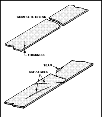
Conductor (run) and pad damage is very common. The technician must examine the board for nicks, tears, or scratches that have not broken the circuit, as well as for complete breaks, as shown in figure 3-

23. Crack damage may exist as nicks or scratches in the conductor. These nicks or scratches must be

repaired if over one-tenth of the cross-sectional area of the conductor is affected as current-carrying capability is reduced. Cracks may also penetrate the conductor.

clip_image002Figure 3-23.—Pcb conductor damage.

CRACK REPAIR.—Four techniques are used to repair cracks in printed circuit conductors. One method is to flow solder across the crack to form a solder bridge. This is not a high-reliability repair since the solder in the break will crack easily.

The second method is to lap-solder a piece of wire across the crack. This method produces a stronger bond than a solder bridge; but it is not highly reliable, as the solder may crack.

A third repair technique is to drill a hole through the board where the crack is located and then to install an eyelet in the hole and solder it into place.

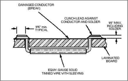
The fourth method is to use the clinched-staple method, shown in figure 3-24. It is the most reliable method and is recommended in nearly all cases.

clip_image004Figure 3-24.—Clinched-staple repair of broken conductor.

Pads or conductor runs may be completely missing from the board. These missing pads or runs must be replaced. Also included in this type of damage are conductors that are present but damaged beyond repair.

REPLACING DAMAGED OR MISSING CONDUCTORS.—The procedures used to replace damaged or missing conductors are essentially the same as using the clinched-staple method of conductor repair.

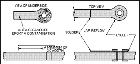
REPLACING THE TERMINATION PAD.—Many times the termination pad, as well as part of the conductor, is missing on the board. In these cases, a replacement pad is obtained from a scrap circuit board. Refer to figure 3-25 as you study each step.

clip_image006Figure 3-25.—Replacement of damaged termination pad.

The underside of the replacement pad and the area where it will be installed is cleaned. An epoxy is used to fasten the replacement pad to the board. An eyelet is installed to reinforce the pad before the epoxy sets and cures. This ensures a good mechanical bond between the board and pad and provides good electrical contact for components. After the epoxy cures, the new pad is lap-soldered to the original run.

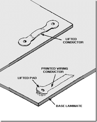
REPAIRING DELAMINATED CONDUCTORS.—DELAMINATED CONDUCTORS (figure 3-

26) are classified as conductors no longer bonded to the board surface. Separation of the laminations may occur only on a part of the conductor. Proper epoxying techniques ensure complete bonding of the

conductor to the circuit board laminate. The following procedures are used to obtain a proper bond:

clip_image007

Figure 3-26.—Delaminated conductors.

1. A small amount of epoxy is mixed and applied to the conductor and the conductor path; no areas are left uncoated.

2. The conductor is clamped firmly against the board surface until the epoxy has completely cured.

REPLACING EYELETS.—Eyelets have been referred to in several places in this topic. Not only are they used for through-the-board terminations, but also to reinforce some types of board repairs. As with any kind of material, eyelets are subject to damage. Eyelets may break, they may be installed improperly, or they may be missing from the equipment. When an eyelet is missing or damaged, regardless of the kind of damage, it should be replaced. The guidelines for the selection and installation of new eyelets are far too complex to explain here. However, they do comprise a large part of the 2M technician’s training.

Repair of Cracked Boards

When boards are cracked, the length and depth of the cracks must be determined. Also, the disruption to conductors and components caused by cracks must be determined by visual inspection. To avoid causing additional damage, the technician must exercise care when examining cracked boards and

must not flex the board. Rebuilding techniques must be used to repair damage, such as cracks, breaks, and holes that extend through the board. The following steps are used to repair cracks:

1. Abrasive methods are used to remove all chips and fractured material.

2. The edges of the removed area are beveled and undercut to provide bond strength.

3. A smoothly surfaced, nonporous object is fastened tightly against one side of the removed area.

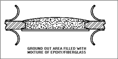
4. The cutaway area is filled with a compound of epoxy and powdered fiberglass (figure 3-27).

Extreme care is exercised to prevent the formation of voids or air bubbles in the mixture.

clip_image009Figure 3-27.—Repair of cracked pcbs.

5. The surface of the filled area is smoothed to make it level with the surface of the original board.

6. The board is cured, smoothed, redrilled, and cleaned.

Broken Board Repair

Broken boards should be examined to determine if all parts of the board are present and if circuit conductors or components are affected by the break. They are also examined to determine if the broken pieces may be rejoined reliably or if new pieces must be manufactured.

Breaks and holes are repaired in the same manner as cracks unless broken pieces are missing or the hole exceeds 1/2 inch in diameter. In such cases, the following repair steps are used:

1. The same technique used in repairing cracks is used to prepare the damaged edge.

2. A piece as close in size to the missing area as possible is cut from a scrap board of the same type and thickness. The edges of this piece are prepared in the same manner as the edges of the hole.

3. A smooth-surfaced object is tightly fastened over one side of the repair area, and the board is firmly clamped in an immovable position with the uncovered area facing up.

4. The replacement piece is positioned as nearly as possible to the original board configuration and firmly clamped into place.

5. The repair is completed using the same epoxy-fiberglass mixture and repair techniques used in the patching repair method discussed in the following section on burned board repair.

Burned Board Repair

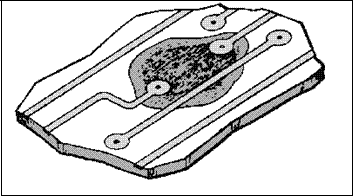
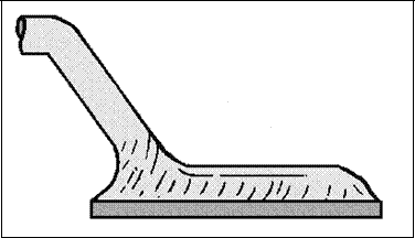
Scorched, charred, or deeply burned boards should be inspected to determine the size of the discolored area and to identify melted or blackened conductors and burned, melted, or blackened components. The depth of the damage, which may range from a slight surface discoloration to a hole burned through the circuit board, should also be determined. Damage not extending through the board may be repaired by patching (figure 3-28). The following procedure is used in the repair of these boards.

clip_image011Figure 3-28.—Repair of surface damage.

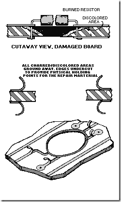
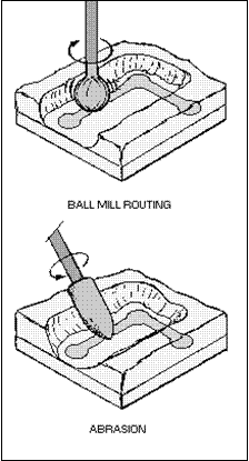
1. If the board is scorched, charred, or burned, all discolored board material is removed by abrasive methods, as shown in figure 3-29. Several components in the affected area may have to be desoldered and removed before the repair is continued.

clip_image012

Figure 3-29.—Repair of burned boards.

2. Repairable delaminations not extending to the edge of the circuit board should be cut away by abrasive methods until no delaminated material remains.

3. Delaminated material is not removed if it is repairable.

4. After all damaged board material is removed, the edge of the removed area is beveled and undercut to provide holding points for the repair material.

5. Solvent is used to clean thoroughly and to remove all loose particles.

6. A compound of epoxy and powdered fiberglass is mixed and used to fill the cutaway area.

7. The epoxy repair mixture is cured according to the manufacturer’s instructions.

8. The surface of the filled area is leveled after the compound is cured.

9. If delaminations extend to the edge of the board, the delaminated layers are filled completely with the repair mixture and clamped firmly together between two flat surfaces.

10. After the cure is completed, abrasive methods are used to smooth the repaired surface to the same level as the original board.

11. If necessary, needed holes are redrilled in the damaged area, runs are replaced, eyelets and components are installed, and the area is cleaned. Figure 3-30 shows the repaired area ready for components.

clip_image014Figure 3-30.—Repaired board ready for components.

Q29. List three causes of damage to printed circuit boards.

Q30. What is the preferred method of repairing cracked runs on boards?

Q31. Damaged or missing termination pads are replaced using what procedure? Q32. How is board damage caused by technicians?

Q33. What combination of materials is used to patch or build up damaged areas of boards?


Miniature And Micro miniature Repair Procedures: Installation and Soldering of Printed Circuit Components, Soldering of PCB Components and Removal and Replacement of Dips.

INSTALLATION AND SOLDERING OF PRINTED CIRCUIT COMPONENTS

The 2M technician should restore the electronic assembly at least to the original manufacturer’s standards. Parts should always be remounted or reassembled in the same position and with termination methods used by the original manufacturer. This approach ensures a continuation of the original reliability of the system.

High reliability connections require thoroughly cleaned surfaces, proper component lead formation and termination, and appropriate placement of components on the board. The following paragraphs describe the procedures for properly installing components on a board including the soldering of these components.

Termination Area Preparation

The termination areas on the board and the component leads are thoroughly cleaned to remove oxide, old solder, and other contaminants. Old or excess solder is removed by one of the desoldering techniques explained earlier in this topic. A fine abrasive, such as an oil-free typewriter eraser, is used to remove oxides. This is not necessary if the area has just been desoldered. All areas to be soldered are cleaned with a solvent and then dried with a lint-free tissue to remove cleaning residue.

Component Lead Preparation

Component leads are formed before installation. Both machine- and hand-forming methods are used to form the leads. Improper lead formation causes many repairs to be unacceptable. Damage to the SEALS (point where lead enters the body of the component) occurs easily during the forming process and results in component failure. Consequently, lead-forming procedures have been established. To control the lead-forming operation and ensure conformity and quality of repairs, the technician should ensure the following:

1. The component is centered between the holes, and component leads are formed with proper bend-radii and body seal-to-bend distance.

2. The possibility of straining component body seals during lead forming is eliminated.

3. Stress relief loops are formed without straining component seals while at the same time providing the desired lead-to-lead distances.

4. Leads are measured and formed for both horizontal and vertical component mounting.

5. Transistor leads are formed to suit standard hole spacing.

Lead-Forming Specifications.

Component leads are formed to provide proper lead spacing.

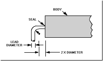
  • · The minimum distance between the seal (where the lead enters the body of the component) and the start of the lead bend must be no less than twice the diameter of the lead, as shown in figure 3-13.

clip_image001

Figure 3-13.—Minimum distance lead bend to component body.

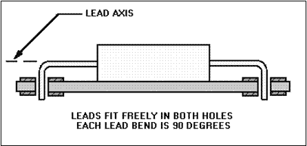
  • · Leads must be approximately 90 degrees from their major axis to ensure free movement in hole terminations, as shown in figure 3-14.

clip_image003Figure 3-14.—Ideal lead formation.

  • · In lead-forming, the lead must not be damaged by nicking.
  • · Energy from the bending action must not be transmitted into the component body.

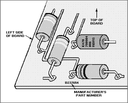
COMPONENT PLACEMENT.—Where possible, parts are remounted or reassembled as they were in the original manufacturing process. To aid recognition, manufacturers use a coding system of colored dots, bands, letters, numbers, and signs. Replacement components are mounted to make all identification markings readable without disturbing the component. When components are mounted like the original, all the identification markings are readable from a single point.

Component identification reads uniformly from left to right, top to bottom, unless polarity requirements determine otherwise, as shown in figure 3-15. To locate the top, position the board so the part number may be read like a page in a book. By definition, the top of the board is the edge above the part number.

clip_image005Figure 3-15.—Component arrangement.

When possible, component identification markings should be visible after installation. If you must choose between identification and electrical value markings, the priority of selection is as follows: (1) electrical value, (2) reliability level, and (3) part number.

Components are normally mounted parallel to and on the side opposite the printed circuitry and in contact with the board.

FORMATION OF PROPER LEAD TERMINATION.—After component leads are formed and inserted into the board, the proper lead length and termination are made before the lead is soldered. Generally, if the original manufacturer clinched (either full or semi) the component leads, the replacement part is reinstalled with clinched leads.

When clinching is required, leads on single- and double-sided boards are securely clinched in the direction of the printed wiring connected to the pad. Clinching is performed with tools that prevent damage to the pad or printed wiring. The lead is clinched in the direction of the conductor by bending the lead. The leads are clipped so that their minimum clinched length is equal to the radius of the pad. Under no circumstances does the clinched lead extend beyond the pad diameter. Natural springback away from the pad or printed wiring is acceptable. A gap between the lead end and the pad or printed wiring is acceptable when further clinching endangers the pad or printed wiring. These guidelines ensure uniform lead length.

Q14. To what standards should a technician restore electronic assemblies? Q15. How is oxide removed from pads and component leads?

Q16. Leads are formed approximately how many degrees from their major axis?

Q17. When you replace components, identification marks must meet what requirements?

Q18. In what direction are component leads clinched on single- and double-sided boards?

Soldering of PCB Components

The fundamental principles of solder application must be understood and observed to ensure consistent and satisfactory results. As discussed in topic 2, the soldering process involves a metal-solvent action that joins two metals by dissolving a small amount of the metals at their point of contact.

SOLDERABILITY.—As the solder interacts with the base metals, a good metallurgical bond is obtained and metallic continuity is established. This continuity is good for electrical and heat conductivity as well as for strength. Solderability measures the ease with which molten solder wets the surfaces of the metals being joined. WETTING means the molten solder leaves a continuous permanent film on the metal surface. Wetting can only be done properly on a clean surface. All dirt and grease must be removed and no oxide layer must exist on the metal surface. Using abrasives and/or flux to remove these contaminants produces highly solderable surfaces.

HEAT SOURCE.—The soldering process requires sufficient heat to produce alloy- or metal-solvent action. Heat sources include CONDUCTIVE, RESISTIVE, CONVECTIVE, and RADIANT types. The type of heat source most commonly used is the conductive-type soldering iron. Delicate electronic assemblies require that the thermal characteristics of a soldering iron be carefully balanced and that the iron and tip be properly matched to the job. Successful soldering depends on the combination of the iron tip temperature, the capacity of the iron to sustain temperature, the time of iron contact with the joint, and the relative mass and heat transfer characteristics of the object being soldered.

SELECTION OF PROPER TIP.—The amount of heat and how it is controlled are critical factors to the soldering process. The tip of the soldering iron transfers heat from the iron to the work. The shape and size of the tip are mainly determined by the type of work to be performed. The tip size and the wattage of the element must be capable of rapidly heating the mass to the melting temperature of solder.

After the proper tip is selected and attached to the iron, the operator may control the heat by using the variable-voltage control. The most efficient soldering temperature is approximately 550 degrees Fahrenheit. Ideally, the joint should be brought to this temperature rapidly and held there for a short period of time. In most cases the soldering action should be completed within 2 or 3 seconds. When soldering a small-mass connection, control the heat by decreasing the size of the tip.

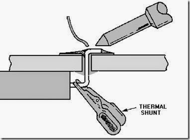
Before heat is applied to solder the joint, a thermal shunt is attached to sensitive component leads (diodes, transistors, and ICs). A thermal shunt is used to conduct heat away from the component. Because of its large heat content and high thermal conductivity, copper is usually used to make thermal shunts. Aluminum also has good conductivity but a smaller heat content; it is also used to conduct heat, especially if damage from the physical weight of the clamp is possible. Many types, shapes, and sizes of thermal shunts are available. The most commonly used is the clamp design; this is a spring clip (similar to an alligator clip) that easily fastens onto the part lead, as shown in figure 3-16.

clip_image007

Figure 3-16.—Thermal shunt.

APPLICATION OF SOLDER AND SOLDERING IRON TIP.—Before solder is applied to the joint, the surface temperature of the parts being soldered is increased above the solder melting point. In general, the soldering iron is applied to the point of greatest mass at the connection. This increases the heat in the parts to be soldered. Solder is then applied to a clean, fluxed, and properly heated surface. When properly applied, the solder melts and flows without direct contact with the heat source and provides a smooth, even surface that feathers to a thin edge.

Molten solder forms between the tip and the joint, creating a heat bridge or thermal linkage. This heat bridge causes the tip to become part of the joint and allows rapid heat transfer. A solder (heat) bridge is formed by melting a small amount of solder at the junction of the tip and the mass being soldered as the iron is applied. After the tip makes contact with the lead and the pad and after the heat bridge is established, the solder is applied with a wiping motion to form the solder bond. The completed solder joint should be bright and shiny in appearance. It should have no cracks or pits, and the solder should cover the pad. Examples of preferred solder joints are shown in figure 3-17. They are referred to as full fillet joints.

clip_image009Figure 3-17.—Preferred solder joint.

When a solder joint is completed, solvent must be used to remove all flux residue. The two most highly recommended solvents, in the order of their effectiveness, are 99.5 percent pure ethyl alcohol and 99.5 percent pure isopropyl alcohol.

Q19. What is solderability?

Q20. What is the most common source of heat in electronic soldering? Q21. What determines the shape and size of a soldering iron tip?

Q22. What term describes a device used to conduct heat away from a component? Q23. What is the appearance of a properly soldered joint?

REMOVAL AND REPLACEMENT OF DIPS

In topic 1 you learned the advantages of DIPs. They are easily inserted by hand or machine and require no special spreaders, spacers, insulators, or lead-forming tools. Standard hand tools and soldering equipment can be used to remove and replace DIPS.

DIPs may be mounted on a board in two ways: (1) They may be mounted by plugging them into DIP mounting sockets that are soldered to the printed circuit boards or (2) they are soldered in place and may or may not be conformally coated. Although plug-ins are very easy to service, they lack the reliability of soldered-in units, do not meet MILSPECS, and are seldom used in military designed equipment. They are susceptible to loosening because of vibration and to poor electrical contact because of dust and dirt and corrosion.

Removal of Plug-In DIPs

To remove plug in DIPs, use an approved DIP puller, such as the one shown in figure 3-18. The puller shown is a plastic device that slips over the ends of the DIP and lifts the DIP evenly out of the socket. Before the DIP is removed, the board is marked or a sketch is made of the DIP reference mark location; then the reference mark for the replacement part will be in the proper position. The DIP is grasped with the puller and gently lifted straight out of the socket. Lifting one side or one end first results in bent leads. If the removed DIP is to be placed back in the circuit, particular care is taken in straightening bent leads to prevent breaking. To straighten bent leads, the technician grasps the wide portion of the lead with one pair of smooth-jaw needle nose pliers; with another pair, the technician then bends the lead into alignment with the other leads. Tools used for lead straightening should be cleaned with solvent to remove contaminants.

clip_image011Figure 3-18.—Typical DIP puller.

To replace a plug-in DIP, the technician should clean the leads with solvent and then check the proper positioning of the reference mark. To do this, the technician holds the DIP body between the thumb and forefinger and places the part on the socket to check pin alignment. The pins are not touched. If all pins are properly aligned, the technician presses the part gently into the socket until the part is firmly seated. As pressure is applied, each pin is checked to ensure that all pins are going into the socket. If pins tend to bend, the part is removed and the pins are straightened. The socket is then inspected to make sure the holes are not obstructed. Then the process is repeated. After a thorough visual inspection, the card should be ready for testing.

Removal and Replacement of Soldered-In DIPs

The removal of soldered-in DIPs without conformal coatings is essentially the same as the removal of discrete components, except that a skipping pattern is always used. A skipping pattern is one that skips from pad to pad, never heating two pads next to each other. This reduces heat accumulation and reduces the chance of damage to the board. Of course, many more leads should be desoldered before the part can be removed. Special care must be exercised to make sure all leads are completely free before an attempt is made to lift the part off the board. If the part is known to be faulty, or if normal removal may damage the board, then the leads should be clipped. Once this has been done, desoldering can be done from both sides of the board. After the clipped leads have been desoldered, they can be removed with tweezers or pliers.

The removal of DIPs from boards with conformal coatings should be completed in the same manner as for other components. The coating should be removed using the preferred method of removal for that particular type of material. The coating should be removed from both sides of the board after masking off the work area. Particular care should be taken when removing the material from around the delicate leads. If the part is to be reused, as much of the coating should be removed from the leads as possible. As with DIPs without conformal coatings, if the part is known to be bad or if the possibility of board damage exists, the leads are clipped; the part and leads are then removed as described earlier in this section. Once the part has been removed, the work area should be completely cleaned to remove any remaining coating or solder.

The steps for replacing a soldered-in DIP are similar to those for replacing a plug-in DIP. Once the part is in position, it is soldered using the same standard used by the manufacturer, or as close to that standard as is possible with the available equipment. The joints should be soldered as quickly as possible using only as much heat as is necessary using a skipping pattern. The repaired card should then be visually inspected for defects in workmanship, and testing of the card should take place. Once the successful repair has been accomplished, a conformal coating should be applied to the work area.

REMOVAL AND REPLACEMENT OF TO PACKAGES

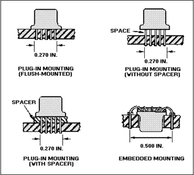
You should recall from chapter 1 of this module, that TO packages are mounted in two ways— plugged-in or embedded. The term plug-in, when referring to TOs, should not be confused with DIP plug-ins. TOs are normally soldered in place. You will come across sockets for TOs, but not as frequently as for DIPs. Figure 3-19 shows the methods of mounting TOs. Notice that plug-ins may either be mounted flush with the board surface or above the surface with or without a spacer. The air gap or spacer may be used by the manufacturer for a particular purpose. This type of mounting could be used for heat dissipation, short circuit protection, or to limit parasitic interaction between components. The spacer also provides additional physical support for the TO. The technician is responsible for using the same procedure as the manufacturer to replace TOs or any other components.

clip_image013Figure 3-19.—TO mounting techniques.

The procedure for removal of plug-in TOs (with or without conformal coatings) is the same as that used for a similarly mounted DIP or discrete component. The conformal coating is removed if required. Leads are desoldered and gently lifted out of the board. Then board terminals and component leads are cleaned.

In some plug-ins, the leads must be formed before they are placed in a circuit. Care should be taken to ensure that seal damage does not occur and that formed leads do not touch the TO case. This would result in a short-circuit.

When the new part or the one that was removed is installed, the leads are slipped through the spacer if required, and the part is properly positioned (reference tab in the proper location). The leads are aligned with the terminal holes and gently pressed into position. The part is soldered into place and visually inspected. Then the card is tested and the conformal coating is replaced if required.

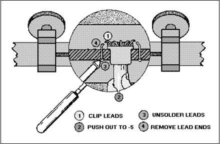
The removal of an imbedded TO package varies only slightly from the removal of other types of mountings. First, the work area is masked and the conformal coating is removed if required. Then the desoldering handpiece is used to remove the solder from each lead. When all leads are free, the TO is pushed out of the board. If all the leads are free, the TO should slip out of the board easily. The package should not be forced out of the board. Excessive pressure may cause additional damage. If the leads are not completely free, the leads must be clipped and removed after the package is out of the board. This process is shown in figure 3-20.

clip_image015Figure 3-20.—Imbedded TO removal.

The most critical part of replacing an imbedded TO is the lead formation. The leads are formed to match the original part as closely as possible. Once the body and leads are seated, the leads can be soldered and the board inspected.

REMOVAL AND REPLACEMENT OF FLAT PACKS

Up to this point, all of the components discussed have had through-the-board leads. In addition, the removal and replacement of discrete components, DIPs, and TOs have been similar.

PLANAR-MOUNTED COMPONENTS (FLAT-PACKS)

Different techniques are used in the removal and replacement of flat packs and devices with on-the- board terminations. Lap-flow solder joints require that the technician pay particular attention to workmanship. Some of the standards of workmanship will be discussed later in this section.

Flat-Pack Removal

Prior to the removal of a flat pack, as with other ICs, a sketch should be prepared to identify the proper positioning of the part. The conformal coating should be removed as required.

To remove the flat pack, the 2M technician carefully heats the leads and lifts them free with tweezers. If the part is to be reused, special care is taken not to damage or bend the leads. The work area around the component should then be thoroughly cleaned and prepared for the new part.

Flat-Pack Replacement

Flat packs attached to boards normally have formed and trimmed leads. Manufacturers form and trim the leads in one operation with a combination die. However, most replacement flat packs are received in a protective holder (figure 3-21) and the leads must be formed and trimmed by hand. Cost prevents equipping the repair station with the variety of tools and dies to form leads because of the variety of component configurations.

clip_image017

Figure 3-21.—Flat pack in protective holder.

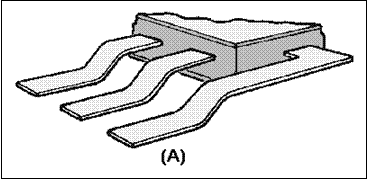
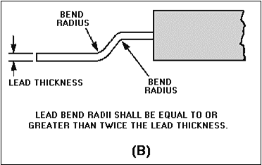
LEAD-BENDING TECHNIQUES.—The 2M technician learns several methods of lead forming that will provide proper contact for soldering and circuit operations. The techniques used to bend leads include the use of specialized tools and such common items as flat toothpicks, bobby pins, and excess component leads. Care is taken not to stress the seal of the component during any step of the lead forming. Figure 3-22 illustrates two views, view (A) and view (B), of properly formed flat-pack leads.

clip_image019Figure 3-22A.—Properly formed flat pack leads.

clip_image021Figure 3-22B.—Properly formed flat pack leads.

Because most replacement flat packs come with leads that are longer than required, they must be trimmed before they are soldered. The removed part is used as a guide in determining lead length. Surgical scissors or scalpels are recommended for use in cutting flat-pack leads. Surgical scissors permit all leads to be cut to the required lead length in a smooth operation with no physical shock transmitted to the IC.

LAP-SOLDERING CONNECTIONS.—Before a connection is lap-soldered, the solder pads are cleaned and pretinned and the component leads are tinned. This is particularly important if they are gold plated. The IC is properly positioned on the pad areas, and the soldering process is a matter of "sweating" the two conductors together. When multilead components, such as ICs, are soldered, a skipping pattern is used to prevent excessive heat buildup in a single area of the board or component. When soldering is completed, all solder connections are thoroughly cleaned. All joints should be inspected and tested. The standards of workmanship are more specific for flat-pack installation.

Q24. When removing the component, under what circumstances may component leads be clipped? Q25. How are imbedded TOs removed once the leads are free?

Q26. How is a flat pack removed from a pcb?

Q27. How do you prevent excessive heat buildup on an area of a board when soldering multilead components?

Q28. What are the two final steps of any repair?


Miniature and micro miniature repair procedures: removal and replacement of discrete components.

REMOVAL AND REPLACEMENT OF DISCRETE COMPONENTS

To properly perform the required repair, the 2M technician must be knowledgeable of the techniques used by manufacturers in the production of electronic assemblies. The techniques, materials, and types of components determine the repair procedures used.

Interconnections and Assemblies

Assemblies may range from simple, single-sided boards with standard-sized components to double- sided or multilayered boards with miniature and microminiature components. The variations in component lead termination and mounting techniques used by manufacturers present the technician with a complex task. For example, the 2M technician is concerned about the type of solder joints on the module. To determine the solder joint type, the technician must consider the board circuitry, hole reinforcement, and lead termination style.

Recall the discussion from topic 1 on printed circuit board construction and the types of interconnections used. Single-sided and some double-sided boards have UNSUPPORTED HOLES where component leads are soldered to the pad. The clearance-hole method is also an interconnection with no hole support. SUPPORTED HOLES are those that have metallic reinforcement along the hole walls.

In addition to the plated-through hole you studied earlier, EYELETS, shown in figure 3-4, view (A), view (B), and view (C), are also used in both manufacturing and repair. These hole-reinforcing devices are usually made of pure copper, but are often plated with gold, tin, or a tin-lead alloy. The copper-based eyelet is pliable; when set, it reduces the possibility of circuit board damage. Eyelets may be inserted into single-sided or double-sided boards and are of three different types – ROLL SET, FUNNEL SET, and FLAT SET. All three are types referred to as INTERFACIAL CONNECTIONS. Interfacial connections identify the procedure of connecting circuitry on one side of a board with the circuitry on the other side.

clip_image002

Figure 3-4A.—Eyelets (interfacial connections). ROLL SET

clip_image004Figure 3-4B.—Eyelets (interfacial connections). FUNNEL SET

clip_image006Figure 3-4C.—Eyelets (interfacial connections). FLAT SET

As you can see, the flat-set eyelet actually provides reinforcement for the pads on both sides of the circuit board and reinforces the hole itself. The design of the roll-set eyelet (which may trap gasses, flux, or other contaminants, and obscures view of the finished solder flow) is not acceptable as a repair technique. The funnel-set eyelet does not provide as much pad reinforcement as the other types. However, it provides better "outgassing" of flux, moisture, or solvents from the space between the eyelet and the hole wall. It also provides a better view of the finished solder connection than the roll-set eyelet.

Lead Terminations

The finished circuit board consists of conductive paths, pads, and drilled holes with components and/or wires assembled directly to it. Leads and wires may terminate in three ways: (1) through the hole in the board, (2) above the surface of the board, or (3) on the surface of the board.

THROUGH-HOLE TERMINATION.—This style provides extra support for the circuit pads, the hole, and the lead by a continuous solder connection from one side of the circuit board to the other. Three basic variations of through-hole termination are the CLINCHED LEAD (two types), STRAIGHT- THROUGH LEAD, and OFFSET PAD.

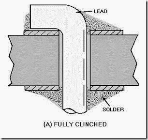
Clinched Lead.—The clinched-lead termination is usually used with unsupported holes, but is found with supported holes as well. Both clinched-lead types, FULLY CLINCHED and SEMICLINCHED (figure 3-5), provide component stability. Like the fully clinched lead, the semi-clinched lead also provides stability during assembly. However, this termination can be easily straightened to allow removal of the solder joint should rework or repair be required. Note that the fully clinched lead is bent 90 degrees while the semiclinched lead is bent 45 degrees.

clip_image008

Figure 3-5A.—Clinched leads. FULLY CLINCHED.

clip_image010

Figure 3-5B.—Clinched leads. SEMICLINCHED

Straight-Through Lead.—Straight-through terminations (figure 3-6) are used by manufacturers when the termination stability is not a prime consideration. This termination type may also be used with unsupported holes. The through-hole termination provides a better, solder-joint contact area and more solder support; the solder runs from the component side to the conductor. The straight-through termination is the easiest to remove and rework.

clip_image012Figure 3-6.—Straight-through termination.

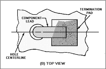
The Offset-Pad Termination.—This termination, shown in view (A) of figure 3-7, is a variation of clinch-lead termination. The pad is set off from the centerline of the hole. The lead clinch is also offset from the hole centerline so that it may contact the pad [view (B)].

clip_image014Figure 3-7A.—Offset pad termination SIDE VIEW.

clip_image016Figure 3-7B.—Offset pad termination TOP VIEW

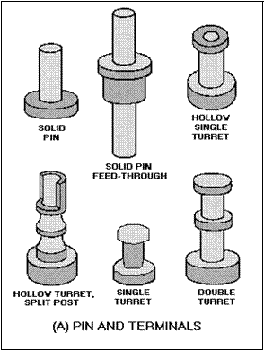
ABOVE-THE-BOARD TERMINATION.—Above-the-board termination is accomplished through the use of terminals or posts. Terminals are used for a variety of reasons. The type of terminal depends on its use. Although many configurations are used, all terminals fall into one of the five categories covered in this section [figure 3-8, views (A) through (E)].

clip_image018Figure 3-8A.—Terminals. PIN AND TERMINALS.

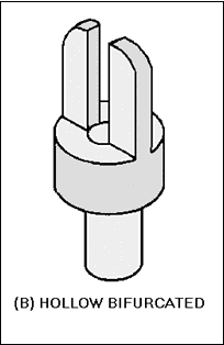
clip_image020Figure 3-8B.—Terminals. HOLLOW.

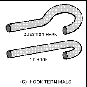
clip_image022Figure 3-8C.—Terminals. HOOK TERMINALS.

clip_image024

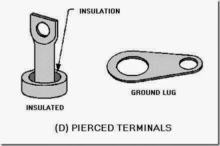
Figure 3-8D.—Terminals. PIERCED TERMINALS.

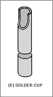
clip_image026Figure 3-8E.—Terminals. SOLDER CUP

  • · PIN TERMINALS AND TURRET TERMINALS [view (A)] are single-post terminals, either insulated or uninsulated, solid or hollow, stud or feed-through. Stud terminals protrude from one side of a board; feed-throughs protrude from both sides.
  • · BIFURCATED OR FORK TERMINALS [view (B)] are solid or hollow double-post terminals.
  • · HOOK TERMINALS [view (C)] are made of cylindrical stock formed in the shape of a hook or question mark.
  • · PERFORATED OR PIERCED TERMINALS [view (D)] describe a class of terminals that uses a hole pierced in flat metal for termination (e.g., terminal lugs).
  • · SOLDER CUP TERMINALS [view (E)] are a common type found on connectors. Turret and bifurcated terminals are used for interfacial connections on printed circuit boards, terminal points for point-to-point wiring, mounting components, and as tie points for interconnecting wiring. Hook terminals are used to provide connection points on sealed devices and terminal boards.

Terminals used for wire or component lead terminations are normally made of brass with a solderable coating. Uninsulated terminals may be installed on an insulating substrate to form a terminal board. They may also be added to a printed circuit board or installed on a metal chassis. Insulated terminals are installed on a metal chassis.

ON-THE-BOARD TERMINATION.—On-the-board termination (figure 3-9) is also called LAP FLOW termination. In a lap flow solder termination, the component lead does not pass through the circuit board. This form of planar mounting may be used with both round and flat leads.

clip_image028Figure 3-9.—On-the-board termination.

Q6. What term is used to identify the procedure of connecting one side of a circuit board with the other?

Q7. Name two types of through-hole termination.

Q8. Turret, bifurcated, and hook terminals are used for what type of termination?

Q9. When a lead is soldered to a pad without passing through the board, it is known as what type of termination?


Miniature And Micro miniature Repair Procedures: Component Desoldering.

Component Desoldering

Most of the damage in printed circuit board repair occurs during disassembly or component removal. More specifically, much of this damage occurs during the desoldering process. To remove components for repair or replacement, the technician must first determine the type of joint that is used to connect the component to the board. The technician may then determine the most effective method for desoldering these connections.

Three generally accepted methods of solder connection removal involve the use of SOLDER WICK, a MANUALLY CONTROLLED VACUUM PLUNGER, or a motorized solder extractor using CONTINUOUS VACUUM AND/OR PRESSURE. Of all the extraction methods currently in use, continuous vacuum is the most versatile and reliable. Desoldering becomes a routine operation and the quantity and quality of desoldering work increases with the use of this technique.

SOLDER WICKING.—IN this technique, finely stranded copper wire or braiding (wick) is saturated with liquid flux. Most commercial wick is impregnated with flux; the liquid flux adds to the effectiveness of the heat transfer and should be used whenever possible. The wick is then applied to a solder joint between the solder and a heated soldering iron tip, as shown in figure 3-10. The combination of heat, molten solder, and air spaced in the wick creates a capillary action and causes the solder to be drawn into the wick.

clip_image001

Figure 3-10.—Solder wicking.

This method should be used to remove surface joints only, such as those found on single-sided and double-sided boards without plated-through holes or eyelets. It can also remove excessive solder from flat surfaces and terminals. The reason is that the capillary action of the wicking is not strong enough to overcome the surface tension of the molten solder or the capillary action of the hole.

MANUALLY CONTROLLED VACUUM PLUNGER.—The second method of removing solder involves a manually controlled and operated, one-shot vacuum source. This vacuum source uses a plunger mechanism with a heat resistant orifice. The vacuum is applied through this orifice. Figure 3-11 shows the latest approved, manual-type desoldering tool. This technique involves melting the solder joint and inserting the solder-extractor tip into the molten solder over the soldering iron tip. The plunger is then released, creating a short pulse of vacuum to remove the molten solder. Although this method offers a positive vacuum rather than the capillary force of the wicking method, it still has limited application. This method will not remove 100 percent of the solder and may cause circuit pad lifting because of the extremely high vacuum generated and the jarring caused by the plunger action.

clip_image003

Figure 3-11.—Manual desoldering tool.

Because 100 percent of the solder cannot be removed, the extraction method is not usually successful with the plated-through solder joint. The component lead in a plated-through hole joint usually rests against the side wall of the hole. Even though most of the molten solder is removed by a vacuum, the small amount of solder left between the lead and side walls causes a SWEAT JOINT to form. A sweat joint is a paper-thin solder joint formed by a minute amount of solder remaining on the conductor lead surfaces.

MOTORIZED VACUUM/PRESSURE METHOD.—The most effective method for solder joint removal is motorized vacuum extraction. The solder extractor unit, described in topic 2, is used for this type of extraction. This method provides controlled combinations of heat and pressure or vacuum for solder removal. The motorized vacuum is controlled by a foot switch and differs from the manual vacuum in that it provides a continuous vacuum. The solder extraction device is a coaxial, in-line instrument similar to a small soldering iron. The device consists of a hollow-tipped heating element, transfer tube, and collecting chamber (in the handle) that collects and solidifies the waste solder. This unit is easily maneuvered, fully controllable, and provides three modes of operation (figure 3-12): (1) heat and vacuum (2) heat and pressure, and (3) hot-air jet. Some power source models provide variable control for pressure and vacuum levels as well as temperature control for the heated tubular tip. The extraction tip and heat source are combined in one tool. Continuous vacuum allows solder removal with a single heat application. Since the slim heating element allows access to confined areas, the technician is protected from contact with the hot, glass, solder-trap chamber. Continuous vacuum extraction is the only consistent method for overcoming the resweat problem for either dual or multilead devices terminating in through-hole solder joints.

clip_image005Figure 3-12A.—Motorized vacuum/pressure solder removal. VACUUM MODE.

clip_image007

Figure 3-12B.—Motorized vacuum/pressure solder removal. PRESSURE MODE.

clip_image009Figure 3-12C.—Motorized vacuum/pressure solder removal. HOT AIR JET MODE.

Motorized Vacuum Method.—In the motorized vacuum method, the heated tip is applied to the solder joint. When melted solder is observed, the vacuum is activated by the technician causing the solder to be withdrawn from the joint and deposited into the chamber. If the lead is preclipped, it may also be drawn into a holding chamber. To prevent SWEATING (reforming a solder joint) to the side walls of the plated-through hole joint, the lead is "stirred" with the tip while applying the vacuum. This permits cool air to flow into and around the lead and side walls causing them to cool.

Motorized Pressure Method.—In the pressure method, the tip is used to apply heat to a pin for melting a sweat joint. The air pressure is forced through the hole to melt sweat joints without contacting

the delicate pad. This method is seldom used because it is not effective in preventing sweating of the lead to the hole nor for cooling the workpiece.

Hot-Air Jet Method.—The hot-air jet method uses pressure-controlled, heated air to transfer heat to the solder joint without physical contact from a solder iron. This permits the reflow of delicate joints while minimizing mechanical damage.

When the solder is removed from the lead and pad area, the technician can observe the actual condition of the lead contact to the pad area and the amount of the remaining solder joint. From these observed conditions, the technician can then determine a method of removing the component and lead.

With straight-through terminations, the component and lead may be lifted gently from uncoated boards with pliers or tweezers. Working with clinched leads on uncoated boards requires that all sweat joints be removed and that the leads be unclinched before removal.

The techniques that have been described represent the successful methods of desoldering components. As mentioned at the beginning of this section, the 2M technician must decide which method is best suited for the type of solder joint. Two commonly used but unacceptable methods of solder removal are heat-and-shake and heat-and-pull methods.

In the heat-and-shake method, the solder joint is melted and then the molten solder is shaken from the connection. In some cases, the shaking action may include striking the assembly against a surface to shake the molten solder out of the joint. This method should NEVER be used because all the solder may not be removed and the solder may splatter over other areas of the board. In addition, striking the board against a surface can lead to broken boards, damaged components, and lifted pads or conductors.

The heat-and-pull method uses a soldering iron or gang-heater blocks to melt individual or multiple solder joints. The component leads are pulled when the solder is melted. This method has many shortcomings because of potential damage and should NOT be attempted. Heating blocks are patterned to suit specific configurations; but when used on multiple-lead connections, the joints may not be uniformly heated. Uneven heating results in plated-through hole damage, pad delamination, or blistering. Damage can also result when lead terminations are pulled through the board.

When desoldering is complete, the workpiece must undergo a careful physical inspection for damage to the circuit board and the remaining components. The technician should also check the board for scorching or charring caused by component failure. Sometimes MEASLING is present. Measling is the appearance of light-colored spots. It is caused by small areas of fiberglass strands that have been damaged by epoxy overcuring, heat, abrasion, or internal moisture. No cracks or breaks should be visible in the board material. None of the remaining components should be cracked, broken, or show signs of overheating. The solder joints should be of good quality and not covered by loose or splattered solder, which may cause shorts. The technician should examine the board for nicked, cracked, lifted, or delaminated conductors and lifted or delaminated pads.

Q10. When does most printed circuit board damage occur?

Q11. What procedure involves the use of finely braided copper wire to remove solder? Q12. What is the most effective method of solder removal?

Q13. When, if at all, should the heat-and-shake or the heat-and-pull methods of solder removal be used?


Miniature And Micro miniature Repair Procedures: Miniature and Micro miniature Electronic Repair Procedures And Conformal Coatings.

MINIATURE AND MICROMINIATURE REPAIR PROCEDURES

LEARNING OBJECTIVES

Upon completion of this topic, the student will be able to:

1. Explain the purpose of conformal coatings and the methods used for removal and replacement of these coatings.

2. Explain the methods and practices for the removal and replacement of discrete components on printed circuit boards.

3. Identify types of damage to printed circuit boards, and describe the repair procedures for each type of repair.

4. Describe the removal and replacement of the dual-in-line integrated circuit.

5. Describe the removal and replacement of the TO-5 integrated circuit.

6. Describe the removal and replacement of the flat-pack integrated circuit.

7. Describe the types of damage to which many microelectronic components are susceptible and methods of preventing damage.

8. Explain safety precautions as they relate to 2M repair.

INTRODUCTION

As you progress in your training as a technician, you will find that the skill and knowledge levels required to maintain electronic systems become more demanding. The increased use of miniature and microminiature electronic circuits, circuit complexity, and new manufacturing techniques will make your job more challenging. To maintain and repair equipment effectively, you will have to duplicate with limited facilities what was accomplished in the factory with extensive facilities. Printed circuit boards that were manufactured completely by machine will have to be repaired by hand.

To meet the needs for repairing the full range of electronic equipment, you must be properly trained. You must be capable of performing high-quality, reliable repairs to the latest circuitry.

MINIATURE AND MICROMINIATURE ELECTRONIC REPAIR PROCEDURES

As mentioned at the beginning of topic 2, 2M repair personnel must undergo specialized training. They are trained for a particular level of repair and must be certified at that level. Also, recertification is required to ensure the continued high-quality repair ability of these technicians.

CAUTION

THIS SECTION IS NOT, IN ANY WAY, TO BE USED BY YOU AS AUTHORIZATION TO ATTEMPT THESE TYPES OF REPAIRS WITHOUT OFFICIAL 2M CERTIFICATION.

In the following sections, you will study the general procedures used in the repair, removal, and replacement of specific types of electronic components. By studying these procedures, you will become familiar with some of the more common types of repair work. Before repair work can be performed on a miniature or microminiature assembly, the technician must consider the type of specialized coating that usually covers the assembly. These coatings are referred to as CONFORMAL COATINGS.

CONFORMAL COATINGS

Conformal coatings are protective material applied to electronic assemblies to prevent damage from corrosion, moisture, and stress. These coatings include epoxy, parylene, silicone, polyurethane, varnish, and lacquer. Coatings are applied in a liquid form; when dry, they exhibit characteristics that improve reliability. These characteristics are:

  • · Heat conductivity to carry heat away from components
  • · Hardness and strength to support and protect components
  • · Low moisture absorption
  • · Electrical insulation
Conformal Coating Removal

Because of the characteristics that conformal coatings exhibit, they must be removed before any work can be done on printed circuit boards. The coating must be removed from all lead and pad/eyelet areas of the component. It should also be removed to or below the widest point of the component body. Complete removal of the coating from the board is not done.

Methods of coating removal are thermal, mechanical, and chemical. The method of removal depends on the type of coating used. Table 3-1 shows suggested methods of removal of some types. Note that most of the methods are variations of mechanical removal.

image

The coating material can best be identified through proper documentation; for example, technical manuals and engineering drawings. If this information is not available, the experienced technician can usually determine the type of material by testing the, hardness, transparency, thickness, and solvent solubility of the coating. The thermal (heat) properties may also be tested to determine the ease of removal of the coating by heat. The methods of removal discussed here describe the basic concept, but not the step-by-step "how to" procedures.

THERMAL REMOVAL.—Thermal removal consists of using controlled heat through specially shaped tips attached to a handpiece. Soldering irons should never be used for coating removal because the high temperatures will cause the coatings to char, possibly damaging the board materials. Modified tips or cutting blades heated by soldering irons also are not used; they may not have proper heat capacity or allow the hand control necessary for effective removal. Also, the thin plating of the circuit may be damaged by scraping.

The thermal parting tool, used with the variable power supply, has interchangeable tips, as shown in figure 3-1, that allow for efficient coating removal. These thin, blade-like instruments act as heat generators and will maintain the heat levels necessary to accomplish the work. Tips can be changed easily to suit the configuration of the workpiece. These tips cool quickly after removal of power because their small thermal mass and special alloy material easily give up residual heat.

clip_image004

Figure 3-1.—Thermal parting tips.

The softening or breakdown point of different coatings vary, which is a concern when you are using this method. Ideally, the softening, point is below the solder melting temperature. However, when the softening point is equal to or above the solder melting point, you must take care in applying heat at the solder joint or in component areas. The work must be performed rapidly to limit the heating of the area involved and to prevent damage to the board and other components.

HOT-AIR JET REMOVAL.—In principle, the hot-air jet method of coating removal uses controlled, temperature-regulated air to soften or break down the coating, as shown in figure 3-2. By controlling the temperature, flow rate, and shape of the jet, you may remove coatings from almost any workpiece configuration without causing any damage. When you use the hot-air jet, you do not allow it to physically contact the workpiece surface. Delicate work handled in this manner permits you to observe the removal process.

clip_image006Figure 3-2.—Hot air jet conformal coating removal.

POWER-TOOL REMOVAL DESCRIPTION.—Power-tool removal is the use of abrasive grinding or cutting to mechanically remove coatings. Abrasive grinding/rubbing techniques are effective on thin coatings (less than 0.025 inch) while abrasive cutting methods are effective on coatings greater than 0.025 inch. This method permits consistent and precise removal of coatings without mechanical damage or dangerous heating to electronic components. A variable-speed mechanical drive handpiece permits fingertip-control and proper speed and torque to ease the handling of gum-type coatings. A variety of rotary abrasive materials and cutting tools is required for removal of the various coating types. These specially designed tools include BALL MILLS, BURRS, and ROTARY BRUSHES.

The ball mill design places the most efficient cutting area on the side of the ball rather than at the end. Different mill sizes are used to enter small areas where thick coatings need to be removed (ROUTED). Rubberized abrasives of the proper grade and grit are ideally suited for removing thin, hard coatings from flat surfaces; soft coatings adhere to and coat the abrasive causing it to become ineffective. Rotary bristle brushes work better than rubberized abrasives on contoured or irregular surfaces, such as soldered connections, because the bristles conform to surface irregularities. Ball mill routing and abrasion removal are shown in figure 3-3.

clip_image008Figure 3-3.—Rotary tool conformal coating removal.

CUT AND PEEL.—Silicone coatings (also referred to as RTV) can easily be removed by cutting and peeling. As with all mechanical removal methods, care must be taken to prevent damage to either components or boards.

CHEMICAL REMOVAL.—Chemical removal uses solvents to break down the coatings. General application is not recommended as the solvent may cause damage to the boards by dissolving the adhesive materials that bond the circuits to the boards. These solvents may also dissolve the POTTING COMPOUNDS (insulating material that completely seals a component or assembly) used on other parts or assemblies. Only thin acrylic coatings (less than 0.025 inch) are readily removable by solvents. Mild solvents, such as ISOPROPYL ALCOHOL, XYLENE, or TRICHLOROETHANE, may be used to remove soluble coatings on a spot basis.

Evaluations show that many tool and technique combinations have proven to be reliable and effective in coating removal; no single method is the best in all situations. When the technician is determining the best method of coating removal to use, the first consideration is the effect that it will have on the equipment.

Conformal Coating Replacement

Once the required repairs have been completed the conformal coating must be replaced. To ensure the same protective characteristics, you should use the same type of replacement coating as that removed.

Conformal coating application techniques vary widely. These techniques depend on material type, required thickness of application, and the effect of environmental conditions on curing. These procedures cannot be effectively discussed here.

Q1. What material is applied to electronic assemblies to prevent damage from corrosion, moisture, and stress?

Q2. What three methods are used to remove protective material? Q3. What chemicals are used to remove protective material?

Q4. Abrasion, cutting, and peeling are examples of what type of protective material removal? Q5. Why should the coating material be replaced once the required repair has been completed?


Miniature/Micro miniature (2m) Repair Program and High-Reliability Soldering: Test Equipment and Repair Stations.

TEST EQUIPMENT

Microelectronic developments have had a great impact on the test equipment, tools, and facilities necessary to maintain systems using this technology. This section discusses, in general terms, the importance of these developments.

Early electronic systems could be completely checked-out with general-purpose electronic test equipment (GPETE), such as multimeters, oscilloscopes, and signal generators. Using this equipment to individually test the microelectronics components in one of today’s very complex electronic systems would be extremely difficult if not impossible. Therefore, improvements in system testing procedures have been necessary.

One such improvement in system testing is the design of a method that can test systems at various functional levels. This allows groups of components to be tested as a whole and reduces the time required to test components individually. One advantage of this method is that complete test plans can be written to provide the best sequencing of tests for wave shape or voltage outputs for each functional level. This method of testing has led to the development of special test sets, called AUTOMATED TEST EQUIPMENT (ATE). These test sets are capable of simulating actual operating conditions of the system being tested. Appropriate signal voltages are applied by the test set to the various functional levels of the system, and the output of each level is monitored. Testing sequences are prewritten and steps may be switched-in manually or automatically. The limits for each functional level are preprogrammed to give either a "go/no-go" indication or diagnose a fault to a component. A go/no-go indication means that a functional level either meets the test specifications (go) or fails to meet the specifications (no-go).

If a no-go indication is observed for a given function, the area of the system in which it occurs is then further tested. You can test the trouble area by using general purpose electronic test equipment and the troubleshooting manual for the system. General purpose electronic test equipment (GPETE) will be discussed later in this topic. (Effective fault isolation at this point depends on the experience of the technician and the quality of the troubleshooting manual.) After the fault is located, the defective part is then replaced or repaired, depending on the nature of the defect. At this stage, the defective part is usually a circuit card, a module, or a discrete part, such as a switch, relay, transistor, or resistor.

BUILT-IN TEST EQUIPMENT

One type of fault isolation that can be either on-line or off-line is BUILT-IN TEST EQUIPMENT (BITE). BITE is any device that is permanently mounted in the prime equipment (system); it is used only for testing the equipment or system in which it is installed either independently or in association with external test equipment. The specific types of BITE are too varied to discuss here, but may be as simple as a set of meters and switches or as complex as a computer-controlled diagnostic system.

ON-LINE TEST EQUIPMENT

Functional-level testing and modular design have been successfully applied to most electronic systems in use today; however, the trend toward increasing the number of subassemblies within a module by incorporating microelectronics will make this method of testing less and less effective.

The increased circuit density and packaging possible with microelectronic components makes troubleshooting and fault location difficult or, in some cases, impossible. The technician’s efforts must be aided if timely repairs to microelectronic systems are to be achieved. These repairs are particularly significant when considered in the light of the very stringent availability requirements for today’s systems. This dilemma has led to the present trend of developing both ON-LINE and OFF-LINE automatic test systems. The on-line systems are designed to continuously monitor performance and to automatically isolate faults to removable assemblies. Off-line systems automatically check removable assemblies and isolate faults to the component level.

Two on-line systems, the TEST EVALUATION AND MONITORING SYSTEM (TEAMS) and the CENTRALIZED AUTOMATIC TEST SYSTEM (CATS), are presently in production or under development by the Navy.

Test Evaluation and Monitoring System (TEAMS)

TEAMS is an on-line system that continuously monitors the performance of electronic systems and isolates faults to a removable assembly. This system is controlled by a computer using a test program on perforated or magnetic tape, cassettes, or disks. Displays are used to present the status of the equipment and to provide data with instructions for fault localization. Lights, usually an LED, are used to indicate which equipments are being tested and also which equipments are in an out-of-tolerance condition. A printer provides a read out copy of the test results. These results are used by maintenance personnel to isolate the fault in a removable assembly to a replaceable part.

Centralized Automatic Test System (CATS)

CATS is an on-line system that continuously monitors the performance of electronic systems, predicts system performance trends, and isolates faults to removable assemblies. CATS, however, is computer controlled and the instructions are preprogrammed in the computer memory. The status of the electronic system being monitored by CATS is presented in various forms. Information concerning a failed module is presented on a status- and fault-isolation indicator to alert the maintenance technician of the need for a replacement module. If equipment design does not permit module replacement, complete electrical schematics and fault-isolation procedures will be made available to the maintenance technician.

OFF-LINE TEST EQUIPMENT

The Navy has under development an advanced assembly tester designated Naval Electronics Laboratory Assembly Tester (NELAT). This tester is an off-line, general-purpose test system designed to check-out and isolate faults in electronic plug-in assemblies, modules, and printed circuit boards. Equipped with a complete range of instrumentation, the system allows testing to be accomplished automatically, semiautomatically, or manually. In the automatic mode, a complete range of stimuli generators and monitors are connected and switched by means of a microfilmed test program.

The NELAT incorporates modular electronic assemblies that will facilitate updating of the system. The system is designed for use aboard ship. When put into service, this tester will greatly improve the technician’s capability in the checkout and fault isolation of microelectronic assemblies.

Another important system for off-line testing is the Versatile Avionic Shop Test System (VAST). VAST is used in the aviation community for fault isolation in aviation electronics (avionics) equipment on ships and shore commands with aircraft INTERMEDIATE MAINTENANCE DEPARTMENTS (AIMDs). It is an automatic, high-speed, computer controlled, general-purpose test set that will isolate faults to the component level.

GENERAL-PURPOSE ELECTRONIC TEST EQUIPMENT (GPETE)

When no automatic means of accomplishing fault isolation is available, general-purpose electronic test equipment and good troubleshooting procedures is used; however, such fault diagnosis should be attempted only by experienced technicians. Misuse of electrical probes and test equipment may permanently damage boards or microelectronic devices attached to them. The proximity of leads to one another and the effects of interconnecting the wiring make the testing of boards extremely difficult; these factors also make drift or current leakage measurements practically impossible.

Boards that have been conformally coated are difficult to probe because the coating is often too thick to penetrate for a good electrical contact. These boards must be removed for electrical probe testing. Many boards, however, are designed with test points that can be monitored either with special test sets or general-purpose test equipment. Another method of obtaining access to a greater number of test points is to use extender cards or cables. The use of extender cards or cables makes these test points easier to check.

Special care should be exercised when probing integrated circuits; they are easily damaged by excessive voltages or currents, and component leads may be physically damaged. Precautions concerning the use of test equipment for troubleshooting equipments containing integrated circuits are similar to those that should be observed when troubleshooting equipment containing semiconductor or other voltage and current-sensitive devices.

Voltage and resistance tests of resistors, transistors, inductors, and so forth, are usually effective in locating complete failures or defects that exhibit large changes from normal circuit characteristics; however, these methods are time-consuming and sometimes unsuccessful. The suspect device often must be desoldered, removed from the circuit, and then retested to verify the fault. If the defect is not verified, the device must be resoldered to the board again. If this procedure has to be repeated several times, or if the board is conformally coated, the defect may never be located. In fact, the circuit may be further damaged by the attempt to locate the fault. For these reasons, the device should never be desoldered until all possible in-circuit tests are performed and the defect verified.

Q7. List the three groups of test equipment used for fault isolation in 2M repair. Q8. What test equipment continuously monitors electronic systems?

Q9. NELAT and VAST are examples of what type of test equipment?

REPAIR STATIONS

In addition to the requirements for special skills, the repair of 2M electronic circuits also requires special tools. Because these tools are delicate and expensive, they are distributed only to trained and certified 2M repair technicians.

2M repair stations are equipped with electrical and mechanical units, tools, and general repair materials. Such equipments are needed to make reliable repairs to miniature and microminiature component circuit boards.

Although most of the tools and equipments are common to both miniature and microminiature repair stations, several pieces of equipment are used solely with microminiature repair. Precision drill presses and stereoscopic-zoom microscopes are examples of microminiature repair equipment normally not found in a miniature repair station. A brief description of some of the tools and equipments and their uses will broaden your knowledge and understanding of 2M repair.

The 2M repair set consists of special electrical units, tools, and materials necessary to make high- reliability repairs to component circuitry. The basic repair set is made up of a repair station power unit, magnifier/light system, card holder, a high-intensity light, a Pana Vise, and a tool chest with specialized tools and materials. As mentioned previously, stations that have microminiature repair capabilities will include a stereoscopic-zoom microscope and precision drill press.

REPAIR STATION POWER UNIT

The repair station power unit is a standardized system that provides controlled soldering and desoldering of all types of solder joint configurations. The unit is shown in figure 2-1. Included in the control unit’s capabilities are:

clip_image002

Figure 2-1.—Repair station power unit.

  • · "Spike free" power switching for attached electrical hand tools to eliminate damage to electrostatic discharge components.
  • · Abrading, milling, drilling, grinding, and cutting using a flexible shaft, rotary-drive machine.

This allows the technician to remove conformal coatings, oxides, eyelets, rivets, damaged board

material, and damaged platings from assemblies.

  • · Lap flow solder connections and thermal removal of conformal coatings.
  • · Resistive and conductive tweezer heating for connector soldering applications.
  • · Thermal wire stripping for removing polyvinyl chloride (PVC) and other synethetic wire coverings.
Power Source

The basic unit houses the power supply, power level indicator, motor control switch, hand tool temperature controls, air pressure and vacuum controls with quick connect fittings, positive ground terminal, the mechanical power-drive for the rotary-drive machine, and a vacuum/pressure pump. A two- position foot pedal, to the left of the power unit in the illustration, allows hand-free operation for all ancillary (additional) handpieces. The first detent on the pedal provides power to the voltage heating outputs. The second detent activates the motor drive or vacuum/pressure pump.

Handpieces

The handpieces used with the power unit are shown in figures 2-2 and 2-3. The lap flow handpiece, view (A) of figure 2-2, is used with the variable low-voltage power source. This handpiece allows removal of conformal coatings, release of sweat joints, and lap flow soldering capability. (Lap flow soldering will be discussed in topic 3.) The thermal wire stripper in view (B) is used to remove insulation from various sizes of wire easily and cleanly.

clip_image004

Figure 2-2.—Low voltage Handpiece.

clip_image006

Figure 2-3.—Motorized solder extrator.

The resistive tweezers, shown in view (C), are used for soldering components. Two sizes 165 views are provided to meet the needs of the technician. Both the thermal stripper and the resistive tweezers are used with the low-voltage power supply.

The solder extractor, shown in view (A) of figure 2-3, is connected to the variable high-voltage outlet. This handpiece allows airflow application (at controlled temperatures) of a vacuum or pressure to the selected area. Five sizes of extractor tips are provided, as shown in view (B). You can determine the one to be used by matching the tip with the circuit pad and the component being desoldered.

Soldering Irons

A soldering iron is shown in figure 2-4. This is connected to the 115-volt ac variable outlet of the power unit. You control the temperature by adjusting the voltage. The iron has replaceable tips. Chosen for their long life and good heat conductivity, soldering iron tips are high quality with iron-clad over copper construction. The tip shape and size and the heat range used are determined by the area and mass to be soldered.

clip_image008

Figure 2-4.—Soldering iron.

ROTARY-DRIVE MACHINE

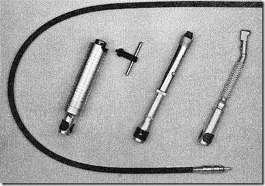
This variable-speed, rotary power drive adapts to standard diameter shank drill bits, ball mills, wheels, disks, brushes, and mandrels for most drilling and abrasive removal techniques (figure 2-5).
clip_image010

Figure 2-5.—Rotary-drive machine handpieces.

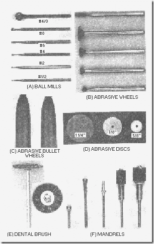
The accessories used with the rotary-drive tool are shown in views (A) through (F) of figure 2-6. Abrasive ball mills, wheels, discs, and brushes are either premounted on mandrels or can be mounted by the technician on the mandrels provided. These attachments are used for sanding and smoothing repaired areas, drilling holes, removing conformal coatings, and repairing burned or damaged areas. A chuck- equipped handpiece allows it to accept rotary tools with varying shank sizes.
clip_image011

Figure 2-6.—Rotary-drive machine accessories. BALL MILLS

CIRCUIT CARD HOLDER AND MAGNIFIER

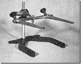
The circuit card holder is an adjustable, rotatable holder for virtually any size circuit card. Figure 2-7 shows the circuit card holder [view (A)] and the magnifier unit [view (B)]. The magnifier unit provides magnification when detail provided by a microscope is not required. The special lens allows the technician to view a rectangular area of over 14 square inches with low distortion, fine resolution, and excellent depth of field. The magnifier unit, which includes high intensity lamps, adapts to the vertical shaft of the circuit card holder.
clip_image013

Figure 2-7.—Card holder and magnifier.

HIGH-INTENSITY LIGHT

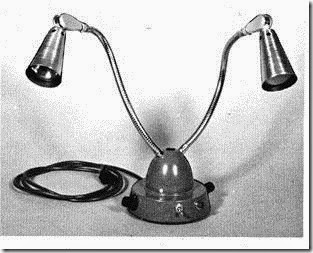
The high-intensity light provides a variable, high-intensity, portable light source over the work area. The two flexible arms permit both front and back lighting of the workpiece and provide a balanced light that eliminates shadows (figure 2-8).
clip_image015

Figure 2-8.—High intensity lamp.

The high-intensity light uses 115-volt, 60-hertz input power. One brightness knob controls a flood- type bulb, and the other knob controls a spot-type bulb.

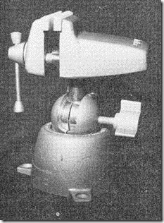
PANA VISE

This nylon-jawed, multiposition vise can rotate and tilt. With this flexibility the technician can achieve any compound angle for holding a workpiece during assembly, modification, or repair (figure 2-9).
clip_image017

Figure 2-9.—Pana Vise.

HAND TOOLS

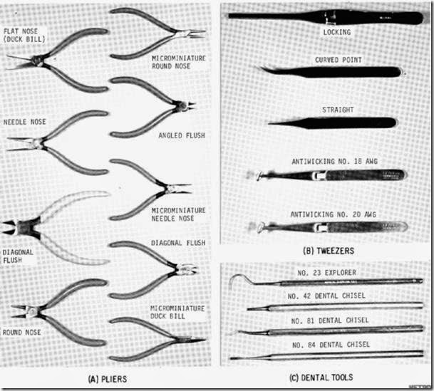
Figure 2-10, views (A) through (C), shows some representative types of hand tools used in 2M repair procedures.
clip_image019

Figure 2-10.—Pliers, tweezers, and dental tools.

Pliers

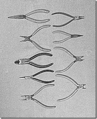
In view (A), the figure shows the pliers preferred for 2M repair procedures. These precision pliers have a long and useful life if handled and cared for properly. The flush-cutting pliers are used to cut various sizes of wire and component leads. The needlenose, roundnose, and flatnose pliers are used for forming, looping, and bending wires and component leads. They are also used for gripping components and leads during removal or installation.
clip_image021

Figure 2-10a.—Pliers.

Tweezers

View (B) shows tweezers contained in the 2M repair set. The top two pairs of tweezers are used to hold small components during installation and repair procedures. The other pairs are anti-wicking tweezers used to tin and solder stranded wire leads.

Dental Tools

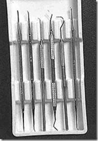
View (C) shows some of the dental tools contained in the 2M repair set. They are used for picking, chipping, abrading, mixing, and smoothing various conformal coatings used on printed circuit boards and other general pcb repair techniques.
clip_image023

Figure 2-10c.—Dental tools.

Eyelet-Setting Tools

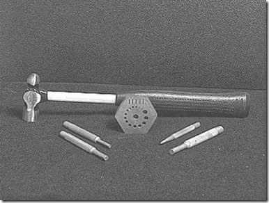
Among the repair procedures required of the 2M repair technician is the replacement of eyelets. Eyelets must sometimes be replaced because of the damage caused by incorrect repair procedures or complete failure of a printed circuit board. Figure 2-11 illustrates the tools used to replace these eyelets. Eyelets will be discussed in topic 3.
clip_image025

Figure 2-11.—Eyelet-setting tools.

MISCELLANEOUS TOOLS AND SUPPLIES

An assortment of some of the miscellaneous items used in 2M repair are shown in figure 2-12. A variety of brushes, files, scissors, thermal shunts, and consumables, such as solder wick, are included.

Even though all the items are not used in every repair procedure, it is extremely important that they be available for use should the need arise.
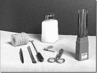
clip_image027

Figure 2-12.—Miscellaneous tools and supplies.

SAFETY EQUIPMENT

The nature of 2M repair requires items to be included in the tool kit for the personal safety of the technicians. The goggles and respirator illustrated in figure 2-13 have been approved for use by the technician. These should be worn at all times where dust, chips, fumes, and other hazardous substances are generated as a result of drilling, grinding, or other repair procedures.
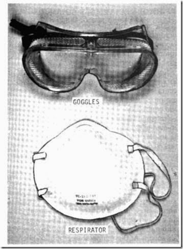
clip_image029

Figure 2-13.—Safety equipment.

STEREOSCOPIC-ZOOM MICROSCOPE

The stereoscopic-zoom microscope provides a versatile optical viewing system. This viewing system is used in the fault detection, fault isolation, and repair of complex microminiature circuit boards and components. Figure 2-14 shows the microscope mounted on an adjustable stand. The microscope has a minimum of 3.5X and a maximum of 30X magnification to detect hairline cracks in conductor runs and stress cracks in solder joints.
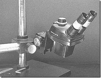
clip_image031

Figure 2-14.—Stereoscopic zoom microscope.

TOOL CHEST

The tool chest (not shown), provides storage space for the electronic repair hand tools, dental tools, abrasive wheels, solder and solder wicks, eyelets, abrasive disks, ball mills, various burrs, and other consumables used with the repair procedures. The chest is portable, lockable, and has variously sized drawers for convenience.

REPLACEMENT PARTS

Replacement parts are provided with the 2M repair set to ensure the technician has the capability to maintain the equipment properly. Actual preventive and corrective maintenance procedures, as well as data on additional spare parts and ordering information, are found in the technical manual for the 2M repair set equipment.

REPAIR STATION FACILITIES

To be effective, 2M electronic component repair must be performed under proper environmental conditions. Repair facility requirements, whether afloat or ashore, include adequate lighting, ventilation, noise considerations, work surface area, ESD (electrostatic discharge) protection, and adequate power availability. The recommended environmental conditions are discussed below. With the exception of requirements imposed by the Naval Environmental Health Center and other authorities for ship and shore work conditions, each activity tailors the requirements to meet local needs.

LIGHTING

The recommended lighting for a work surface is 100 footcandles from a direct lighting source. Light- colored overheads and bulkheads and off-white or pastel workbench tops are used to complement the lighting provided.

VENTILATION

Fumes from burning flux, coating materials, grinding dust, and cleaning solvents require adequate ventilation. The use of toxic, flammable substances, solvents, and coating compounds requires a duct system that vents gasses and vapors. This type of system must be used to prevent contamination often

found in closed ventilation systems. This need is particularly important aboard ship. Vented hoods, ducts, or installations that are vented outside generally meet the minimum standards set by the Naval Environmental Health Center.

NOISE CONSIDERATIONS

Noise in the work area during normal work periods must be no greater than the acceptable level approved for each activity involved. Because the work is tedious and tiring, noise levels should be as low as possible. Ear protectors are required to be worn when a noise level exceeds 85 dB. Ear protectors should also be worn anytime the technician feels distracted by, or uncomfortable with, the noise level.

WORK SURFACE AREA

Work stations should have a minimum work surface of at least 60-inches wide and 30-inches deep. Standard Navy desks are excellent for this purpose. Standard shipboard workbenches are acceptable; however, off-white or pastel-colored heat-resistant tops should be installed on the workbenches. Chairs should be the type with backs and without arms. They should be comfortably padded and of the proper height to match the work surface height. Drawers or other suitable tool storage areas are usually provided.

ELECTROSTATIC DISCHARGE SENSITIVE DEVICE (ESDS) CAPABILITY

A 2M work station should be capable of becoming a static-free work station. This is specified in the Department of Defense Standard, Electrostatic DISCHARGE Control Program for Protection of Electrical and Electronic Parts, Assemblies, and Equipment. ESD will be discussed in greater detail in topic 3.

POWER REQUIREMENTS

No special power source or equipment mounting is required. The 2M repair equipment operates on 115-volt, 60-hertz power. A 15-ampere circuit is sufficient and six individual power receptacles should be available.

HIGH-RELIABILITY SOLDERING

The most common types of miniature and microminiature repair involve the removal and replacement of circuit components. The key to these repairs is a firm knowledge of solder and high- reliability soldering techniques.

Solder is a metal alloy used to join two or more metals with a metallic bond. The bonding occurs when molten solder dissolves a small amount of the metals and then cools to form a solid connection. The solder most commonly used in electronic assemblies is an alloy of tin and lead. Tin-lead alloys are identified by their percentage in the solder; the tin content is given first. Solder marked 60/40 is an alloy of 60 percent tin and 40 percent lead. The two most common alloys used in electronics are 60/40 and 63/37.

The melting temperature of tin-lead solder varies depending on the percentage of each metal. Lead melts at a temperature of 621 degrees Fahrenheit, and tin melts at 450 degrees Fahrenheit. Combinations of the two metals melt into a liquid at different temperatures. The 63/37 combination melts into a liquid at 361 degrees Fahrenheit. At this temperature, the alloy changes from a solid directly to a liquid with no plastic or semiliquid state. An alloy with such a sharp changing point is called a EUTECTIC ALLOY.

As the percentages of tin and lead are varied, the melting temperature increases. Alloy of 60/40 melts at 370 degrees Fahrenheit, and alloy of 70/30 melts at approximately 380 degrees Fahrenheit. Alloys, other than eutectic, go through a plastic or semiliquid state in their heating and cooling stages. Solder joints that are disturbed (moved) during the plastic state will result in damaged connections. For this reason, 63/37 solder is the best alloy for electronic work. Solder with 60/40 alloy is also acceptable, but it goes into a plastic state between 361 and 370 degrees Fahrenheit. When soldering joints with 60/40 alloy, you must exercise extreme care to prevent movement of the component during cooling.

USE OF FLUX IN SOLDER BONDING

Reliable solder connections can only be accomplished with clean surfaces. Using solvents and abrasives to clean the surfaces to be soldered is essential if you are to achieve good solder connections. In almost all cases, however, this cleaning process is insufficient because oxides form rapidly on heated metal surfaces. The rapid formation of oxides creates a nonmetallic film that prevents solder from contacting the metal. Good metal-to-metal contact must be obtained before good soldering joints may take place. Flux removes these surface oxides from metals to be soldered and keeps them removed during the soldering operation. Flux chemically breaks down surface oxides and causes the oxide film to loosen and break free from the metals being soldered.

Soldering fluxes are divided into three classifications or groups: CHLORIDE FLUX (commonly called ACID), ORGANIC FLUX, and ROSIN FLUX. Each flux has characteristics specific to its own group. Chloride fluxes are the most active of the three groups. They are effective on all common metals except aluminum and magnesium. Chloride fluxes, however, are NOT suitable for electronic soldering because they are highly corrosive, electrically conductive, and are difficult to remove from the soldered joint.

Organic fluxes are nearly as active as chloride fluxes, yet are less corrosive and easier to remove than chloride fluxes. Also, these fluxes are NOT satisfactory for electronic soldering because they must be removed completely to prevent corrosion.

Rosin fluxes ARE ideally suited to electronic soldering because of their molecular structure. The most common flux used in electronic soldering is a solution of pure rosin dissolved in suitable solvent. This solution works well with the tin- or solder-dipped metals commonly used for wires, lugs, and connectors. While inert at normal temperatures, rosin fluxes break down and become highly active at soldering temperatures. In addition, rosin is nonconductive.

Most electronic solder, in wire form, is made with one or more cores of rosin flux. When the joint or connection is heated and the wire solder is applied to the joint (not the iron), the flux flows onto the surface of the joint and removes the oxide. This process aids the wetting action of the solder. With enough heat the solder flows and replaces the flux. Insufficient heat results in a poor connection because the solder does not replace the flux.

Q10. Stereoscopic-zoom microscopes and precision drill presses are normally associated with what type of repair station?

Q11. Solder used in electronic repair is normally an alloy of what two elements? Q12. In soldering, what alloy changes directly from a solid state to a liquid state? Q13. Flux aids in soldering by removing what from surfaces to be soldered?

Q14. What type(s) of flux should never be used on electronic equipment?