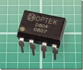
timer:What It Does,Monostable Mode,Astable Mode,How It Works,Time Calculation in Monostable Mode,Time Calculation in Astable Mode,Dual Monostable Timers,How to Use It,Burst Mode,Dead Timer and CMOS Confused with Bipolar.

timer

A device that creates a single timed pulse, or a series of timed pulses with timed intervals between them, is properly known as a multivibrator, although the generic term timer has become much more common and is used here.

Three types of multivibrator exist: astable, monostable, and bistable. The behavior of astable multivibrators and monostable multivibrators is described in detail in this entry. A timer chip can also be made to function as a bistable multivibrator. This is described briefly below, but it is not a designed function of a timer. The primary discussion of bistable multivibrators will be found in the entry of this encyclopedia dealing with flip- flops.

What It Does

A monostable timer emits a single timed pulse of fixed length in response to a triggering input that is usually of shorter duration. Many monostable timers are also capable of running in astable mode, in which the timer spontaneously emits an ongoing stream of timed pulses with timed gaps between them. A dual-mode timer can run in either mode, determined either by external components attached to it, or (less commonly) by changing the status of a mode selection pin.

Monostable Mode

In monostable mode, the timer emits a pulse in response to a change from high to low voltage (or, less commonly, from low to high voltage) at a trigger pin. Most timers respond to a voltage level at the trigger pin, but some are insensitive to any persistent pin state and only respond to a voltage transition. This is known as edge triggering.

The pulse generated by the timer may consist of a change from low to high (or, less commonly, from high to low) at an output pin. The length of the pulse will be determined by external com- ponents, and is independent of the duration of the triggering event, although in some cases, an output pulse may be prolonged by retriggering the timer prematurely. This is discussed below.

At the end of the output pulse, the timer reverts to its quiescent state, and remains inactive until it is triggered again.

A monostable timer can control the duration of an event, such as the time for which a light re- mains on after it has been triggered by a motion sensor. Alternatively, the timer can impose a de- lay, such as the interval during which a paper towel dispenser refuses to respond after a towel has been dispensed. A timer can also be useful to generate a clean pulse in response to an un- stable or noisy input, as from a manually operat- ed pushbutton.

Astable Mode

In astable mode, a timer will generally trigger it- self as soon as power is connected, without any need for an external stimulus. However, the out- put can be suppressed by applying an appropri- ate voltage to a reset pin.

External components will determine the duration of each pulse and the gap between it and the next pulse. The pulse stream can be slow enough to control the flashing of a turn signal in a 1980s automobile, or fast enough to control the bit rate in a data stream from a computer.

Modern timer circuits are often incorporated in chips that have other purposes. The flashing of a turn signal in a modern car, for instance, is now likely to be timed by a microcontroller that man- ages many other functions. Still, chips that are purely designed as timers remain widely used and are very commonly available in numerous through-hole and surface-mount formats.

How It Works

The duration of a single pulse in monostable mode, or the frequency of pulses in astable mode, is most commonly determined by an ex- ternal RC network consisting of a resistor in series with a capacitor. The charging time of the capac- itor is determined by its own size and by the value of the resistor. The discharge time will be deter- mined in the same way. A comparator inside the timer is often used to detect when the potential on the capacitor reaches a reference voltage that is established by a voltage divider inside the chip.

Variants
The 555 Timer

An eight-pin integrated circuit manufactured by Signetics under part number 555 was the world’s first fully functioned timer chip, introduced in 1972. It combined two comparators with a flip- flop (see Chapter 11) to enable great versatility while maintaining excellent stability over a wide range of supply voltages and operating temperatures. Subsequent timers have been heavily in- fluenced by this design. A typical 555 timer chip is shown in Figure 9-1.

clip_image005

Figure 9-1. A typical 555 timer chip. Functionally identical versions in which the “555” identifier is preceded or followed by different letter combinations are available from many different manufacturers.

The 555 was designed by one individual, Hans Camenzind, working as an independent consultant for Signetics. According to a transcript of an interview with Camenzind maintained online at the Transistor Museum, “There was nothing like it at the time. You had to use quite a few discrete components—a comparator, a Zener diode or even two. It was not a simple circuit.”

The 555 timer quickly became the most widely used chip in the world, and was still selling an annual estimated 1 billion units three decades after its introduction. It has been used in space- craft, in intermittent windshield wiper controllers, in the early Apple II (to flash the cursor), and in children’s toys. Like many chips of its era, its design was unprotected by patents, allowing it to be copied by numerous manufacturers.

The initial version was built around bipolar transistors, and consequently is referred to as the bipolar version or (more often) the TTL version, this being a reference to transistor-transistor log- ic protocol. Within a few years, CMOS versions based around MOSFETs were developed. They reduced the ability of the chip to sink or source

current at its output pin, but consumed far less power, making them better suited to battery- operated products. The CMOS versions were and still are pin-compatible with the original bipolar version, both in through-hole and surface- mount formats. Their timing parameters are usually the same.

555 Monostable Operation

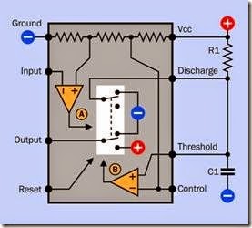
The internal functionality of a 555 timer wired to run in monostable mode is illustrated in Figure 9-2 with the chip seen from above. The pins are identified in datasheets by the names shown. To assist in visualizing the behavior of the chip, this figure represents the internal flip-flop as a switch which can be moved by either of two internal comparators, or by an input from the Reset pin.

clip_image008

Figure 9-2. The internal functions of a 555 chip, with its flip-flop represented as a switch that can be moved by ei- ther of two comparators, or by a low voltage on the Reset pin. An external resistor and capacitor, shown as R1 and C1, cause the timer to run in monostable (one-shot) mode, generating a single high pulse when the state of the Input pin is pulled from high to low.

Inside the chip, three resistances of 5K each are connected between V+ (positive supply voltage) and negative ground. It has been suggested that the part number of the 555 chip was derived from these three 5K resistors, but Hans Camenzind has pointed out that Signetics was already using three-digit part numbers beginning with the number 5, and probably chose the 555 part num- ber because the sales department had high ex- pectations for the chip and wanted its number to be easily memorable. (A similar rationale ex- plains the part number of the 2N2222 transistor.)

The resistances inside the timer function as a voltage divider, providing a reference of 1/3 of V+ to the noninverting pin of Comparator A and 2/3 of V+ to the inverting pin of Comparator B. (See Chapter 6 for an explanation of the functioning of comparators.)

When power is initially supplied to the timer, if the Input pin is at a high state, Comparator A has a low output, and the flip-flop remains in its “up” position, allowing the Output pin to remain in a low state. The flip-flop also grounds the lower end of R1, which prevents any charge from ac- cumulating on capacitor C1.

If the state of the Input pin is pulled down externally to a voltage less than 1/3 of V+, Comparator A now creates a high output that changes the flip-flop to its “down” position, sending a high signal out through the Output pin. At the same time, C1 is no longer grounded, and begins to charge at a rate determined by its own size and by the value of R1. When the charge on the capacitor exceeds 2/3 of V+, it activates Comparator B, which forces the flip-flop into its “up” position. The Output pin goes low, C1 discharges it- self into the Discharge pin, and the timer’s cycle is at an end.

The low voltage on the Input pin of the timer must end before the end of the output cycle. If the voltage on the Input pin remains low, it will re-trigger the timer, prolonging the output pulse.

A pullup resistor may be used on the Input pin to avoid false triggering, especially if an external electromechanical switch or pushbutton is used to pull down the Input pin voltage.

The Reset pin should normally be held high, either by being connected directly to positive sup- ply voltage (if the reset function will not be needed) or by using a pullup resistor. If the Reset pin is pulled low, this will always interrupt an output pulse regardless of the timer’s current status.

If a voltage higher or lower than 2/3 of V+ is applied to the Control pin, this will change the reference voltage on Comparator B, which deter- mines when the charging cycle of C1 ends and the discharge cycle begins. A lower reference voltage will shorten each output pulse by allowing a lower charge limit for C1. If the control volt- age drops to 1/3 of V+ (or less), the capacitor will not charge at all, and the pulse length will diminish to zero. If the control voltage rises to be- come equal to V+, the capacitor will never quite reach that level, and the pulse length will be- come infinite. A workable range for the control voltage is therefore 40% to 90% of V+.

Because the Control pin is an input to the chip, it should be grounded through a 0.01µF ceramic capacitor if it will not be used. This is especially important in CMOS versions of the timer.

A defect of the bipolar 555 is that it creates a voltage spike when its Output pin changes state. If it will be sharing a circuit with sensitive components, a 0.01µF bypass capacitor should be added as closely as possible between the V+ pin and negative ground. The voltage-spike problem was largely resolved by the CMOS 555.

555 Astable Operation

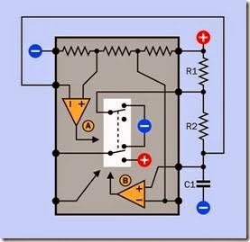
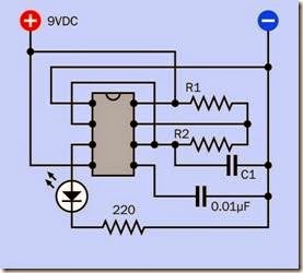
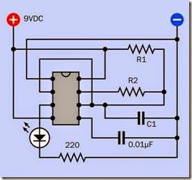
In Figure 9-3, the 555 timer chip is shown with external components and connections to run it in astable mode. The pin names remain the same but have been omitted from this diagram be- cause of limited space. The labeling of the two external resistors and capacitor as R1, R2, and C1 is universal in datasheets and manufacturers’ documentation.

When the timer is powered up initially, capacitor C1 has not yet accumulated any charge. Conse- quently, the state of the Threshold pin is low. But the Threshold pin is connected externally with the Input pin, for astable operation. Consequent- ly, the Input pin is low, which forces the flip-flop into its “down” state, creating a high output. This happens almost instantaneously.

clip_image010

Figure 9-3. The internal functions of a 555 chip, with two external resistors and a capacitor wired to run the timer in astable (free-running) mode.

While the flip-flop is “down,” the Discharge pin is not grounded, and current flowing through R1 and R2 begins to charge the capacitor. When the charge exceeds 2/3 of positive supply voltage, Comparator B forces the flip-flop into its “up” position. This ends the high pulse on the Output pin, and starts to drain the charge from the capacitor through R2, into the Discharge pin. How- ever, the voltage on the capacitor is still being shared by the Input pin, and when it diminishes to 1/3 of V+, the Input pin reactivates Compara- tor A, starting the cycle over again.

The functions of the Reset and Control pins are the same as in monostable mode. Because volt- age applied to the Control pin changes the length of each pulse and the gaps between pul- ses, it has the effect of adjusting the frequency of the output in astable mode.

When power is first connected to the timer, C1 must initially charge from an assumed state of zero potential to 2/3 V+. Because subsequent cycles will begin when the capacitor is at 1/3 V+, the first high output pulse from the timer will be slightly longer than subsequent output pulses. This is unimportant in most applications, especially because the rate at which a capacitor ac- cumulates charge is greater when beginning from 0V than when it has reached 1/3 V+. Still, the longer initial pulse can be noticeable when the timer is running slowly.

Because the capacitor charges through R1 and R2 in series, but discharges only through R2, the length of each positive output pulse in astable mode is always greater than the gap between pulses. Two strategies have been used to over- come this limitation. See “Separate Control of High and Low Output Times” on page 80.

556 Timer

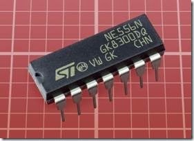
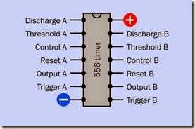
The 556 consists of two 555 bipolar-type timers in one package. An example of the chip is shown in Figure 9-4. The pinouts are shown in Figure 9-5. Although 556 timers have become relatively uncommon compared with the 555, they are still being manufactured in through- hole and surface-mount versions by companies such as Texas Instruments and STMicroelectron- ics, under part numbers such as NA556, NE556, SA556, and SE556 (with various letters or letter pairs appended). Each timer in the chip has its own set of inputs and outputs, but the timers share the same V+ and ground voltages.

558 Timer

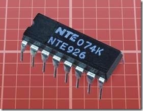
This 16-pin chip is now uncommon, and many versions have become obsolete. It has been iden- tified by a part number such as NE558 although different prefix letters may be used. The NTE926, shown in Figure 9-6, is actually a 558 timer.

The chip contains four 555 timers sharing a common power supply, common ground, and common control-pin input. For each internal timer, the Threshold and Discharge functions are connected internally, so that the timers can only be used in one-shot mode. However, one timer can trigger another at the end of its cycle, and the second timer can then retrigger the first, to create an astable effect.

Each timer is edge-triggered by a voltage transition (from high to low), instead of being sensitive to a voltage level, as is the case with a 555 timer. Consequently the timers in the 558 chip are in- sensitive to a constant (DC) voltage.

clip_image012

Figure 9-4. An example of the 556 timer chip.

clip_image014

Figure 9-5. The 556 timer contains two separate 555 timers sharing the same power supply and ground. The pin functions for timer A and timer B are shown here.

The output from each timer is an open collector, and therefore requires an external pullup resistor. Each output is capable of sinking up to 100mA.

clip_image016

Figure 9-6. The NTE926 is a 558 timer chip.

CMOS 555 Timer

While the part numbers of many CMOS versions are significantly different from part numbers of the bipolar versions, in some instances the CMOS numbers are only distinguished by a couple of initial letters. The ST Microelectronics TS555 ser- ies and Texas Instruments TLC555 series, for ex- ample, use MOSFETs internally. The ST Micro- electronics SE555 series and Texas Instruments SA555 series use bipolar transistors internally.

One way to distinguish between the two types, when searching a website maintained by a parts supplier, is to begin by looking generically for a “555 timer” and then add a search filter to show chips either with a minimum power supply of 3VDC (which will be CMOS) or with a minimum power suply of 4.5VDC (which will be bipolar).

CMOS versions of the 555 timer do not create the power spike that is characteristic of the bipolar versions during output transitions. The CMOS chips can also be powered by a lower voltage (3VDC, or 2VDC in some cases), and will draw significantly less current in their quiescent state. They also require very little current for threshold, trigger, and reset functions.

The wiring of external resistors and capacitors to the CMOS version of the chip, and the internal voltage levels as a fraction of V+, are identical to the original 555 timer. Pin functions are likewise identical. The only disadvantages of CMOS versions are their greater vulnerability to static dis- charge, and their lower output currents. The TLC555, for instance, will source only 15mA (al- though it can sink 10 times that amount). Other manufacturers have different specifications, and datasheets should be checked carefully.

5555 Timer

The 5555 contains a digital counter that enables it to time very long periods. Its full part number is 74HC5555 or 74HCT5555, although these numbers may be preceded or followed by letter combinations identifying the manufacturer. It is not pin-compatible with a 555 timer.

Two input pins are provided, one to trigger the timer on a rising edge, the other on a falling edge, of the input pulse. The inputs are Schmitt- triggered.

The timer is rated for 1Hz to 1MHz (using an external resistor and external capacitor). The counter section can divide the pulse frequency by values ranging from 2 to 256. For longer timed periods, different settings on the digital control pins will divide the frequency by values ranging from 217 through 224 (131,072 through 16,777,216). This enables the timer to achieve a theoretical pulse length lasting for more than 190 days. The timer will accept a clock input from an external oscillator to achieve better accuracy than is available with a resistor-capacitor timing circuit.

7555 Timer

This 8-pin chip is a CMOS version of the 555 timer, manufactured by companies such as Maxim In- tegrated Products and Advanced Linear Devices. Its characteristics are similar to those of CMOS 555 timers listed above, and the pinouts are the same.

7556 Timer

This 14-pin chip contains two 7555 timers, shar- ing common power supply and ground connections. Pinouts are the same as for the original 556 timer, as shown in Figure 9-5.

4047B Timer

This 14-pin CMOS chip was introduced in an ef- fort to address some of the quirks of the 555 timer while also providing additional features. It runs in either monostable or astable mode, selectable by holding one input pin high or another input pin low. In astable mode, its duty cycle is fixed at approximately 50%, a single resistor being used for both charging and discharging the timing ca- pacitor. An additional “oscillator” output runs twice as fast as the regular output.

In monostable mode, the 4047B can be triggered by a positive or negative transition (depending on which of two input pins is used). It ignores steady input states and will also ignore addition- al trigger pulses that occur during the output pulse. However, a retrigger pin is provided to ex- tend the output pulse if desired.

Complementary output pins are provided, one being active-high while the other is active-low.

To time very long periods, the 4047B was de- signed to facilitate connection with an external counter.

The power supply for the 4047B can be as low as 3VDC. Its maximum source or sink output current is only 1mA when powered at 5VDC, but up to 6.8mA when powered at 15VDC.

The chip is still available from manufacturers such as Texas Instruments (which markets it as the CD4047B) in through-hole and surface- mount formats. However, despite its versatility, the 4047B is less popular than dual monostable timers, described in the next section.

Dual Monostable Timers

Various timers that run only in monostable mode are available in dual format (i.e., two timers in one chip). This format became popular partly be- cause two monostable timers can trigger each other to create an astable output, in which the pulse width, and the gap between pulses, can be set by a separate resistor-capacitor pair on each timer. This allows greater flexibility than is avail- able when using a 555 timer.

Most dual monostable timer chips are edge- triggered by a change in input voltage, and will ignore a steady DC voltage. Consequently, the output from one timer can be connected directly to the input of another, and no coupling capacitors are necessary.

As in the 4047B, the user has a choice of two input pins for each timer, one triggered by a transition from low to high, the other triggered by a transition from high to low. Similarly, each timer has two outputs, one shifting from low to high at the start of the output cycle, the other shifting from high to low.

The values of a single resistor and capacitor determine the pulse duration of each timer.

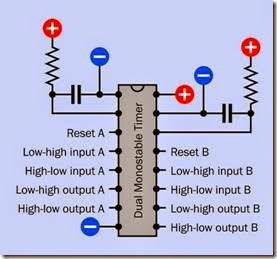
Dual monostable timers often have the numeric sequence 4528 or 4538 in their part numbers. Examples include the HEF4528B from NXP, the M74HC4538 from STMicroelectronics, and the MC14538B from On Semiconductor. The 74123 numeric sequence identifies chips that have a very similar specification, with chip-family identifiers such as HC or LS inserted, as in the 74HC123 and 74LS123, and additional letters added as prefix or suffix. The pinouts of almost all these chips are identical, as shown in Figure 9-7. How- ever, Texas Instruments uses its own numbering system, and datasheets should always be consulted for verification before any connections are made.

Many chips of this type are described as “retriggerable,” meaning that if an additional trigger pulse is applied to the input before an output pulse has ended, the current output pulse will be extended in duration. Check datasheets carefully to determine whether a chip is “retriggerable” or will ignore new inputs during the output pulse.

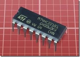
The 74HC221 dual monostable vibrator (pic- tured in Figure 9-8) functions very similarly to the components cited above, but has slightly different pinouts.

clip_image018

Figure 9-7. Pin functions for most 4528, 4538, and 74123 series of dual monostable timer chips. An RC network is shown connected for each timer. Note that Texas Instruments uses different pinouts on its versions.

clip_image020

Figure 9-8. A dual-timer chip containing two monostable multivibrators that can function in astable mode if they are connected externally to trigger each other.

Values
555 Timer Values

The original bipolar version of the 555 timer was designed to operate using a wide range of posi- tive supply voltages, from 4.5VDC to 16VDC.

CMOS versions vary in their recommended V+ values, and datasheets must be consulted for verification.

The output of a bipolar 555 is rated to source or sink up to 200mA. In practice, the maximum cur- rent will be lower when the timer is powered at the low end of its range, around 5VDC. Attempting to source more than 50mA will pull down the voltage internally, affecting operation of the timer.

CMOS versions all impose restrictions on output current, allowing higher values for sinking than sourcing. Again, datasheets must be consulted for the values, which vary widely from one component to another.

The voltage measured on the output pin, when it is used for sourcing current, will always be low- er than the power supply voltage, and a 1.7V drop is commonly specified for bipolar versions. In practice, the voltage drop that is actually measured may be less, and will vary according to the load on the output.

The voltage drop does not increase significantly with a higher supply voltage, and because it is a relatively constant value, it becomes less significant when a higher value for V+ is used.

CMOS versions of the 555 timer achieve a claim- ed output source voltage that is only 0.2V less than the power supply.

When choosing values for R1 and R2, a minimum for each resistor is 5K, although 10K is preferred. Lower values will increase power consumption, and may also allow overload of the internal electronics when the chip sinks current from C1. A typical maximum value for each resistor is 10M.

A high-value capacitor may cause the timer to function less accurately and predictably, be- cause large capacitors generally allow more leak- age. This means that the capacitor will be losing charge at the same time that it is being charged through R1 + R2. If these resistors have high values, and the capacitor has a value of 100µF or more, the rate of charge may be so low that it is

comparable with the rate of leakage. For this reason, a 555 timer is not a good choice for timing intervals much greater than a minute. If a large- value capacitor is used, tantalum is preferable to electrolytic.

The minimum practical value for a timing capacitor is around 100pF. Below this, performance may not be reliable.

Although some CMOS versions may enable fast switching, the shortest practical output pulse for a 555 timer is around 10 microseconds. On the input pin, a triggering pulse of at least 1 micro- second should be used.

Time Calculation in Monostable Mode

If R1 is measured in kilohms and C1 is measured in microfarads, the pulse duration, T, in seconds, of a 555 timer running in monostable mode can be found from this simple formula:

T = 0.0011 * R1 * C1

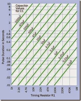
This relationship is the same in all versions of the 555. Figure 9-9 provides a quick and convenient way to find the pulse value using some common values for R1 and C1. Resistors can be obtained with tolerances below plus-or-minus 1%, but ca- pacitors are often rated with an accuracy of only plus-or-minus 20%. This will limit the accuracy of the pulse values shown in the chart.

Time Calculation in Astable Mode

If R1 and R2 are measured in kilohms and C1 is measured in microfarads, the frequency of pul- ses, F (measured in Hz) of a 555 timer running in astable mode can be found from this simple formula:

F = 1440 / ( ( R1 + (2 * R2) ) * C1)

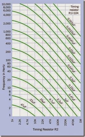
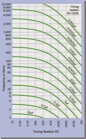
This relationship is found in all versions of the 555. Figure 9-10 shows the frequency for com- mon values of R2 and C1, assuming that the value of R1 is 10K. In Figure 9-11, a value of 100K is as- sumed for R1.

clip_image022

Figure 9-9. To determine the pulse duration of a 555 timer running in monostable mode: find the value of R1 on the horizontal scale, follow its vertical grid line upward to the intersection with a green line which corresponds with the value of capacitor C1, and read across to the vertical scale providing the duration in seconds. Both axes are logarithmic.

Dual Monostable Timers

Dual chips such as the HEF4528B from NXP, the M74HC4538 from STMicroelectronics, the MC14538B from On Semiconductor, and the 74HC123 from Texas Instruments have widely varying requirements for power supply. Some accept a limited range from 3VDC to 6VDC, while others tolerate a range of 3VDC to 20VDC. When powered with 5VDC their required input and output states are compatible with those of 5V logic chips.

Output pins of these chips source and sink no more than 25mA (much less in some instances). Because there are so many variants, they cannot be summarized here, and datasheets must be consulted for details.

clip_image024

Figure 9-10. To obtain the frequency of a 555 timer run- ning in astable mode, when R1 has a value of 10K: find the value of R2 on the horizontal scale, follow its vertical grid line upward to the intersection with a green curve which corresponds with the value of capacitor C1, and read across to the vertical scale providing the frequency in Hertz. Both axes are logarithmic.

As these timers are all monostable, and each timer uses just one resistor and one capacitor, the only formula required is to give the pulse time as a function of these two variables. If R is the resistor value in ohms, and F is the capacitor value in farads, and K is a constant supplied by the manufacturer, the pulse time T, in seconds, is found from the formula:

T = R * F * K

clip_image026

Figure 9-11. To obtain the frequency of a 555 timer running in astable mode, when R1 has a value of 100K: find the value of R2 on the horizontal scale, follow its vertical grid line upward to the intersection with a green curve which corresponds with the value of capacitor C1, and read across to the vertical scale providing the frequency in Hertz. Both axes are logarithmic.

K ranges between 0.3 and 0.7 depending on the manufacturer and also on the voltage being used. Its value should be found in the manufacturer’s datasheet. If R is measured in megohms and F is measured in microfarads, the formula is still valid, as the multipliers cancel each other out.

Generally speaking, these dual monostable CMOS timers are not intended for pulse duration exceeding 1 minute.

The timing capacitor should be no larger than 10µF, as it discharges directly and rapidly through the chip.

How to Use It

Where a timer is required to drive a load such as a relay coil or small motor directly, the original TTL version of the 555 timer will be the only choice. Even in this instance, a protection diode must be used across the inductive device.

For smaller loads and applications in chip-to- chip circuits, CMOS versions of the 555, including the 7555, use less power, cause less electrical interference, and are pin-compatible while using the same formulae to calculate frequency in as- table mode or pulse duration in monostable mode. They are of course more vulnerable to static discharge, and care must be taken to make a connection to every pin (the capacitor that grounds the Control pin, if Control is not going to be used, is mandatory).

In dual monostable timers, unused rising-edge trigger inputs should be tied to V+ while unused falling-edge trigger inputs should be tied to ground. A Reset pin that will not be used should be tied to V+, unless that entire timer section of the chip will be unused, in which case the pin should be grounded.

To measure durations longer than a few minutes, a timer which incorporates a programmable counter to divide the clock frequency is the sensible choice. See the description of the 5555 timer that was included earlier in this entry.

The original bipolar version of the 555 remains a robust choice in hobby applications such as robotics, and its design allows some versatile variations which may even be used in logic circuits. A variety of configurations are shown in the schematics below.

555 Monostable Mode

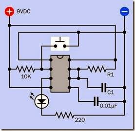
The basic schematic for a 555 timer running in monostable mode is shown in Figure 9-12. In this particular example, a pushbutton that is liable to suffer from switch bounce is connected to the In- put pin of the timer, which responds to the very first connection made by the pushbutton and ignores the subsequent “bounces,” thus producing a “clean” output. To avoid retriggering, which results in a prolonged output pulse, the timer’s output should exceed the time for which the button is likely to be pressed. The output should also exceed the duration of any possible switch bounce, which can otherwise create multiple output pulses. In the schematic, an LED is attached to the timer output for demonstration purposes.

clip_image029

Figure 9-12. The basic monostable configuration of a 555 timer. This particular circuit debounces an input from a pushbutton switch and converts it to a clean pulse of fixed duration, powering an LED for demonstration purposes.

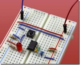
This circuit is shown on a breadboard in Figure 9-13. The red and blue wires, at the top of the photograph, supply 9VDC to the board. R1 is 1M, while C1 is 1µF, creating a pulse of just over 1 second. A tactile switch, just above the timer, provides the input.

clip_image031

Figure 9-13. The basic monostable configuration for a 555 timer, mounted on a breadboard.

555 Astable Mode

A basic schematic for a 555 timer running in as- table mode is shown in Figure 9-14. Once again, an LED is attached to the output for demonstration purposes. If the pulse rate exceeds the persistence of vision, a small loudspeaker can be used instead, in series with a 47Ω resistor and a 100µF capacitor.

clip_image033

Figure 9-14. A 555 timer with external connections and components causing it to run in astable (free-running) mode.

Separate Control of High and Low Output Times

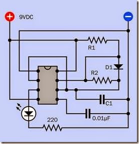
In Figure 9-15, a bypass diode has been added around R2. The capacitor now charges primarily through R1, as the diode has a much lower effective resistance than R2. It discharges only through R2, as the diode blocks current in that direction. Consequently, the length of the high output pulse can be adjusted with the value of R1 only, while the length of the low output pulse can be adjusted with the value of R2 only. The duration of the high output can be lower than, or equal to, the duration of the low output, which is not possible with the basic configuration of components in Figure 9-14.

clip_image035

Figure 9-15. In this circuit, a diode bypasses R2, so that the “on” time and the “off” time of the 555 timer can be set independently of each other, with R1 and R2, respectively.

555 Fifty Percent Astable Duty Cycle: 1

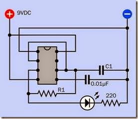
In Figure 9-16, the circuit enables a fixed astable output duration of approximately 50% high and 50% low. Initially, C1 has no charge, pulling the Input of the timer low, and causing it to begin a cycle with a high pulse from the Output pin, as usual. In this demonstration circuit, the output illuminates an LED. At the same time, resistor R1 is attached to the output and charges C1. When the voltage on C1 reaches 2/3 of V+, this is com- municated to the timer Input pin, which ends the “high” cycle and initiates low status on the Out- put pin. This starts to sink the charge from C1, through R1. When the voltage drops to 1/3 V+, this initiates a new cycle. Because only one resis- tor is used to charge and discharge the capacitor, we may imagine that the charge and discharge times should be identical. However, a higher load on the output will probably pull down the output voltage to some extent, lengthening the charge time. Conversely, a load on the Output pin that has low resistance will probably sink at least some of the charge from the capacitor, shorten- ing the discharge cycle.

clip_image037

Figure 9-16. This configuration provides an approximate 50-50 on-off duty cycle at the output pin, although the precise duration will depend on the load.

555 Fifty Percent Astable Duty Cycle: 2

In Figure 9-17, a small modification of the basic astable circuit shown in Figure 9-14 provides an- other way to enable a 50% duty cycle. Compare the two schematics, and you will see that just the connection between R1 and R2 has been altered so that C1 now charges only through R1, and dis-

charges only through R2. However, in this con- figuration the capacitor is discharging into a volt- age divider created by the two resistors. Empirical adjustment of the resistor values may be necessary before the duty cycle is precisely 50%.

clip_image039

Figure 9-17. An alternative configuration to provide an ap- proximate 50-50 on-off duty cycle in a 555 timer.

Use of the 555 Control Pin

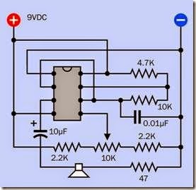
In Figure 9-18, a potentiometer and two series resistors allow a varying voltage to be applied to the Control Pin. This will lengthen or reduce both the charge and the discharge times of the timing capacitor. If values for the capacitor and its associated resistors are chosen to create a frequency of approximately 700Hz, a 10K potentiometer should demonstrate more than an octave of audible tones through the loudspeaker. Other components can be substituted for a potentiometer, creating possibilities for producing pulse-width modulation. Alternatively, if a large capacitor is added between the Control pin and ground while a second 555 timer, running slowly in as- table mode, applies its output to the Control pin, the charging and discharging of the capacitor will apply a smoothly rising and falling voltage. If the first 555 timer is running at an audio frequency, the output will have a “wailing siren” effect.

clip_image041

Figure 9-18. A circuit that allows adjustment of the as- table 555 frequency by increasing or lowering the voltage on the Control pin.

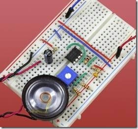
Figure 9-19 shows the components specified in Figure 9-18 mounted on a breadboard.

clip_image043

Figure 9-19. The components in the previous schematic are shown here mounted on a breadboard. They will generate an audio output ranging between approximately 425Hz and 1,075Hz. A lower value for the timing capacitor will shift the audio range higher in frequency.

555 Flip-Flop Emulation

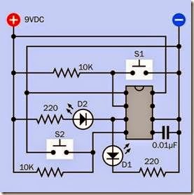
The flip-flop inside a 555 timer can be accessed to control the timer’s outputs. In Figure 9-20, pushbutton switch S1 applies a negative pulse to the Input pin, creating a high output from the timer, which illuminates LED D1. Normally the pulse length would be limited by the charge time of a capacitor attached to the Threshold pin, but in this circuit there is no capacitor, and the Threshold pin is hard-wired to negative ground. So, it never rises to 2/3 of positive power, and the output from the timer remains high indefinitely.

clip_image045

Figure 9-20. A 555 timer can have its timing features dis- abled so that it functions as a flip-flop.

However, if S2 is pressed, it grounds the Reset pin of the timer, which ends the high output and pulls the Output pin down to a low state. D1 goes out and D2 lights up, as the timer is now sinking current through it. When S2 is released, the timer output remains low and D2 remains illuminated, because the Input pin is held high by a pullup resistor. Therefore, the timer now functions in bi- stable mode, as a flip-flop. While this may be seen as an inappropriate use of the chip, because its full functionality is being disabled, its ability to deliver substantial current and to tolerate a wide range of supply voltages may make it more convenient to use than a digital flip-flop. See Chap- ter 11 for more information about flip-flops.

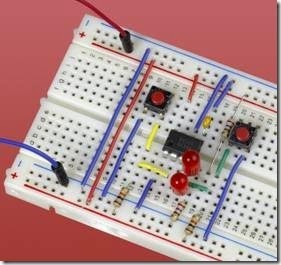
A 555 timer emulating a flip-flop is shown on a breadboard in Figure 9-21.

clip_image047

Figure 9-21. The schematic in which a 555 timer acts as a flip-flop is shown here adapted for a breadboard.

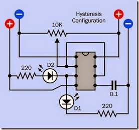
555 Hysteresis

The comparators inside a 555 timer enable the chip to produce hysteresis. In Figure 9-22, the In- put pin and the Threshold pin are shorted together, and C1, the timing capacitor, is omitted. A 10K potentiometer, wired as a voltage divider, delivers a voltage to the Input pin ranging smoothly from V+ to negative ground. As the in- put dips below 1/3 V+, the Output pin goes high, lighting LED D1. Now if the input voltage gradually rises, the output remains high, even as the input rises above 1/3 V+. The output state is “sticky” because the timer does not end an out- put pulse until the Threshold pin tells it to, by reaching 2/3 V+. When this finally occurs, the Output pin goes low, D1 goes out, and D2 comes on, sinking current into the Output pin.

Suppose, now, the input voltage starts to go down again. Once again the output state is “sticky” because it remains low until the Input pin drops below the 1/3 level. When that happens, the output finally flips back to a high state, D2 goes out, and D1 comes on.

In the “dead zone” between 1/3 and 2/3 of supply voltage, the timer remains in its current mode, waiting for the input to stray outside of those limits. This behavior is known as hysteresis, and is of special importance when processing a varying signal, such as the voltage from a temperature sensor, to control an on/off device such as a thermostat. In fact the 10K potentiometer in this demo could be replaced with a thermistor or a phototransistor, wired in series with a resistor to create a voltage divider which will have an input range compatible with the 555 timer. The hysteresis can then be adjusted by varying the supply voltage that powers the timer, as this will change the values of 1/3 V+ and 2/3 V+. Alternatively, varying the voltage on the Control pin will affect the hysteresis.

A comparator can provide much more versatile control of hysteresis by using positive feedback (see Chapter 6 for additional details). But the 555 timer provides a quick-and-simple substitute, and its greater ability to source or sink current enables it to be connected with a wider range of other components.

clip_image049

Figure 9-22. A 555 timer wired so that it creates hystere- sis, when supplied by a variable input voltage.

555 and Coupling Capacitors

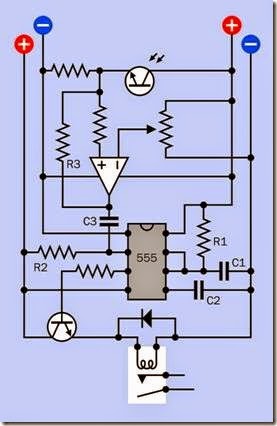
As previously noted, when a basic bipolar 555 timer (and some of its variants) is wired in mono- stable mode, it will retrigger itself indefinitely if its input remains low. One way to avoid this is by using a coupling capacitor. This will pass a transition from high to low, but will then block a steady subsequent voltage. In Figure 9-23, a phototransistor in series with a resistor provides a variable voltage to the noninverting input of a comparator. The reference voltage of the comparator is adjusted with a potentiometer, and resistor R3 provides positive feedback, ensuring that the output from the comparator will be quick and clean. The output from the 555 timer goes through a transistor to the relay, shown at the bottom.

It is important to see the function of the coupling capacitor, C3, with the pullup resistor, R2, which holds the Input pin of the 555 timer high by de- fault. When the output from the comparator drops from high to low, C3 passes this transition to the Input pin of the timer, momentarily over- coming the positive potential, and triggering the timer. After the timer responds, however, C3 blocks any continuation of low voltage from the comparator. Pullup resistor R2 resumes its function of holding the input high, and prevents the timer from being retriggered.

555 Loudspeaker Connection

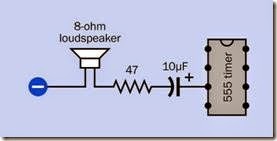
A small 8-ohm loudspeaker can be driven from the output of a bipolar 555 timer running in as- table mode, but should be isolated from it with a 10µF to 100µF capacitor. A series resistor of 47Ω (minimum) should be used. See Figure 9-24.

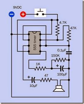
Burst Mode

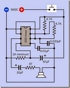
It is sometimes useful to create a short beep of fixed length in response to a button-press. The beep should terminate even if the button is held down. This “burst mode” can be achieved with the circuit in Figure 9-25, where the button con- nects power to a bipolar-type 555 timer running in astable mode, and an RC network applies a decreasing potential to a 47µF capacitor, which is wired to the Reset pin of the timer. The resistor in series with the capacitor will vary the length of the beep. When voltage to the pin drops below approximately 0.3V, output from the timer stops and cannot restart until the button is released.

A resistor of greater than 1.5K may not allow the input value at the reset pin to fall below the volt- age, which is necessary to enable a reset. If a low- er power supply voltage than 9VDC is used, the resistor value should be higher—for example, a 5VDC power supply works well with a 1.5K to 2K resistor.

clip_image051

Figure 9-23. A coupling capacitor (C3) is used in this circuit to isolate the 555 timer from a sustained low input from the comparator. The capacitor only passes a transition from high to low. The rest of the time, the pullup resistor (R3) holds the input high.

clip_image053

Figure 9-24. A small 8-ohm loudspeaker can be attached through a capacitor and a resistor to the output of a bipolar 555 timer.

clip_image055

Figure 9-25. An RC circuit, wired to apply a decreasing voltage on the Reset pin of a bipolar 555 timer, will shut off the timer shortly after it is powered up. This can be used to create a fixed-length beep in response to a button press of any duration.

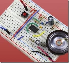
Figure 9-26 shows the components installed on a breadboard.

“You Lose” Game Sound

A timer is a simple, cheap way to create a variety of simple game sounds. The schematic in Figure 9-27 makes a groaning sound as the 100µF capacitor wired to the Control pin of a bipolar- type 555 gradually charges through the 1K resistor. Note that if a larger resistor is paired with a smaller capacitor, the effect will differ. The 150K resistor is included to discharge the capacitor reasonably quickly in time for the next cycle.

clip_image057

Figure 9-26. The “burst mode” circuit installed on a breadboard with a miniature loudspeaker.

What Can Go Wrong
Dead Timer

Like any chip, the 555 can be damaged by over- voltage, excessive source current or sinking cur- rent, static electricity, incorrectly applied polarity of power supply, and other forms of abuse. The TTL version of the timer is fairly robust, but the CMOS type much less so. Check for obvious errors such as lack of supply voltage, incorrect or ambiguous input voltages, and unusual current draw (too high, or none at all, at the V+ pin). Use the meter probes on the actual pins of the chip, in case there is a break in the wiring that feeds them. Because timer chips are cheap, a reserve supply of them should be maintained.

clip_image060

Figure 9-27. An RC circuit, wired to apply an increasingly positive voltage to the Control pin of a bipolar timer running in astable mode, will gradually pull down the frequency at the Output pin, creating a sound that may be useful in simple game applications.

CMOS Confused with Bipolar

The part numbers of some bipolar chips are very similar to those of some CMOS versions, and the chips look physically identical. But the CMOS version is easily overloaded, as it may source only 10mA to 20mA maximum while the TTL version is capable of 200mA. Make sure that your chips are carefully labeled when they are stored.

The Pulse that Never Ends

If a 555 timer responds correctly to a high-to-low transition on the input pin, but the output pulse continues indefinitely, check the voltage on pin 6 to see if the timing capacitor is charging above 2/3 of V+. While a 555 can run from 5VDC, a high- current device on the Output pin can pull down the voltage inside the chip to the point where the capacitor never charges sufficiently to end the cycle.

Also check that the input transition from high to low lasts for a shorter time than the pulse. A per- sistent low input can retrigger the timer.

Erratic Chip Behavior

Possible causes include:

• Floating pins. The Input pin, in particular, should always be connected with a defined voltage (via a 10K pullup resistor, if necessary), and must not be allowed to float at an indeterminate potential.

• Voltage spikes. A timer can be triggered by transients from other components, especial- ly inductive loads. If the input to a monostable timer dips for even a fraction of a second, the timer will initiate a new cycle. A protection diode should be used in conjunction with an inductive load.

• Voltage spikes can also introduce variations in the pulse train from an astable timer.

• TTL versions of the 555 timer will tolerate a wide range of supply voltage, but if a voltage regulator is not used, fluctuations in voltage can have unpredictable consequences.

Interference with Other Components

Because the bipolar version of a 555 timer creates a voltage spike when its output changes state, it can interfere with the normal function of other components, especially CMOS chips. A 0.1µF by- pass capacitor can be applied between the timer’s V+ pin and ground.

Erratic Behavior of Output Devices If a 555 timer powers an output device such as a relay, and the relay is not opening or closing in a reliable manner, first check that it is receiving sufficient voltage. If the 555 timer is powered with 5VDC, its output will be only around 4VDC.

This problem can be avoided by using the output from the timer to control the voltage on the base of a transistor which switches a separate source of power to the relay coil.

Fatal Damage Caused by Inductive Loads

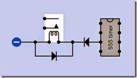
While it is possible to drive an inductive load such as a small motor or relay directly from a TTL 555 timer, two precautions should be taken. First, the motor or the coil of the relay should have a clamping diode added around it, as is standard practice. Second, because the output of the timer is capable of sinking current as well as sourcing current, it can be protected from sinking back- EMF by inserting a diode in series with the load. This is illustrated in Figure 9-28.

clip_image062

Figure 9-28. In addition to a standard protection diode clamped around an inductive load such as a relay coil, the 555 timer can be protected from back-EMF by adding a diode in series. The series diode must of course be rated to carry sufficient current through the coil. When choosing a relay, allowance must be made for the voltage drop that will be imposed by the series diode.

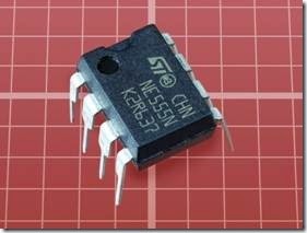
 

digital potentiometer:What It Does,Advantages,How It Works,Variants,Volatile and Nonvolatile Memory,Taper,Data Transfer,SPI,I2C Protocol,Up/Down Protocol,Nonlinear Effects and Data Transfer Too Fast.

digital potentiometer

A digital potentiometer is also known as a digitally adjustable potentiometer, a digitally controlled potentiometer, a digitally programmed potentiometer (with acronym DPP), a digpot, or a digipot. The terms are functionally interchangeable. Because the abbreviation pot is often used to describe an analog potentiometer, some people refer to digital potentiometers colloquially as digital pots. In printed documentation, the letters in pot may be capitalized. Because it is an abbreviation, not an acronym, it is not capitalized here.

Because this component enables digital control of a variable voltage, it is a mixed signal device. It is classified here as an analog chip because it primarily emulates the function of an analog device. It may be thought of as a form of digital-analog converter, although this encyclopedia does not have a section devoted to that type of component or to analog-digital converters, as their application is relatively specialized.

What It Does

This component is an integrated circuit chip that emulates the function of an analog potentiometer. It is often described as being programmable, meaning that its internal resistance can be changed via a control input.

Digital potentiometers are particularly suited for use in conjunction with a microcontroller, which can control the internal resistance of the component. Possible applications include adjustment of the pulse width of an oscillator or multistable multivibrator (e.g., using the Control pin of a 555 timer chip); adjustment of the gain in an op-amp; specification of voltage delivered by a voltage regulator; and adjustment of a band- pass filter.

A digital potentiometer in combination with a microcontroller may also be used in conjunction with a pair of external buttons or a rotational encoder, to adjust the gain of an audio amplifier and for similar applications.

Advantages

A digital potentiometer offers significant advan- tages over an analog potentiometer:

• Reliability. The digital component may be rated for as many as a million cycles (each storing the wiper position in an internal memory location). An analog component may be capable of just a few thousand ad- justment cycles.

• Digital interface.

• Elimination of long signal paths or cable runs. The digital potentiometer can be placed close to other chips, whereas an an- alog potentiometer often has to be some distance away to enable control by the end user. Reduction in the length of signal paths can reduce capacitive effects, while elimination of cable runs will reduce manufacturing costs.

• Reduction in size and weight compared with a manual potentiometer.

A digital potentiometer also has some disadvantages:

• Its internal resistance is somewhat affected by temperature.

• It is not usually capable of passing significant current. Few chips can sink or source more than 20mA at the output, and 1mA is common. The output is primarily intended for connection with other solid-state components that have high impedance.

• Users may prefer the immediacy and tactile feel of a knob attached to an analog poten- tiometer, rather than a pair of buttons or a rotational encoder.

How It Works

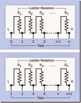
A digital potentiometer changes the point at which a connection is made along a ladder of many fixed resistors connected in series inside the chip. Each end of the ladder, and each inter- section between two adjacent resistors, is known as a tap. The pin that can connect with any of the taps is referred to as the wiper, because it emu- lates the function of a wiper in an analog potentiometer. In reality, a digital potentiometer does not contain a wiper or any other moving parts.

A fully featured digital potentiometer allows access to each end of the ladder through two pins that are often labeled “high” and “low,” even though they are functionally interchangeable (except in the case of a component that simulates a logarithmic taper, as described later). The “low” end of the ladder is sometimes numbered

1. In this case, if there are n resistors, the “high” end of the ladder will be numbered n. Alternatively, if the “low” end of the ladder is numbered 1, and there are n resistors, the “high” end will be numbered n+1. This principle is illustrated in Figure 8-1.

clip_image006

Figure 8-1. Available wiper connections to a resistor lad- der inside a digital potentiometer, showing two numbering systems that may be used.

The “low” pin on a digital potentiometer may be identified as L, or A, or RL, or PA in a datasheet, while the “high” pin may be identified as H, or B, or RH, or PB and the pin that accesses the wiper is typically identified as W, or RW, or PW. Letters L, H, and W are used below. Although the L and H pins are functionally interchangeable, their labels are useful to identify which direction the W connection will move in response to an external signal.

Digital potentiometers are available with as few as 4 or as many as 1,024 taps, but common values are 32, 64, 128, or 256 taps, with 256 being the most common.

No specific schematic symbol represents a digital potentiometer. Often the component is shown as an analog potentiometer symbol inside a box that has a part number, as suggested in Figure 8-2. Control pins and the power supply may be omitted if the schematic is just intended to show logical connections. Alternatively, if the digital potentiometer is depicted in a schematic where it is connected with other components such as a microcontroller, multiple pins and functions may be included, as shown in Figure 8-3. The pins additional to L, H, and W are explained below.

clip_image008

Figure 8-2. There is no single specific symbol to represent a digital potentiometer. It may be shown using an analog potentiometer symbol in a box with a part number, as suggested here, where power connections and additional pins are omitted for clarity.

clip_image010

Figure 8-3. If a digital potentiometer appears in a schematic where it is connected with other components such as a microcontroller, additional pins and functions may be indicated. This generic representation of a digital potentiometer shows some of the functions that can be included.

Variants

A dual digital potentiometer contains two com- plete units, while a quad contains four. Triples exist but are relatively uncommon. A few chips contain six potentiometers. Multiple digital potentiometers in a chip can be used as the digital equivalent of ganged analog potentiometers, for simultaneous synchronized adjustment of multiple inputs in an audio system (two channels in a stereo amplifier, or more in a surround-sound system).

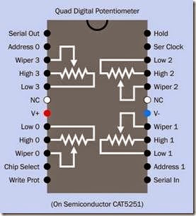
The pinouts of a sophisticated quad digital potentiometer chip are shown in Figure 8-4. Other quad chips have different pinouts and capabili- ties; there is no standardized format as there is with digital logic chips. In this example, the high/ low states of Address 0 and Address 1 select one of the four internal resistor ladders, numbered 0 through 3. The Chip Select pin makes the whole chip either active or inactive. The Write Protect pin disables writing to the internal wiper memory. The Serial Clock pin inputs a reference pulse stream to which the serial input data must be synchronized. The Hold pin pauses the chip while data is being transmitted, allowing the data transmission to be resumed subsequently. The NC pins have no connection.

Volatile and Nonvolatile Memory Any type of digital potentiometer requires memory to store its current wiper position, and this memory may be volatile or nonvolatile. Nonvolatile memory may be indicated in a datasheet by the term NV.

A digital potentiometer with volatile memory will typically reset its wiper to a center-tap position if power is disconnected and then restored. A digital potentiometer with nonvolatile memory will usually restore the most recently used wiper position, provided the chip is fully powered down and then fully powered up without glitches in the supply. If a microcontroller is being used to control the digital potentiometer, it can store the most recent resistance value in its own nonvolatile memory, in which case the type of memory in the potentiometer becomes irrelevant.

clip_image013

Figure 8-4. Pinouts of a sophisticated quad digital potentiometer chip. Other chips will have different pinouts and capabilities. This example is available in surface-mount formats only. See text for details.

Taper

Digital potentiometers are available with linear taper or logarithmic taper. In the former, each resistor in the ladder has the same value. In the latter, values are chosen so that the cumulative resistance between the wiper and the L end of the ladder increases geometrically as the wiper steps toward the H end of the ladder. This is useful in audio applications where sound intensity that increases exponentially may seem to increase linearly when perceived by the human ear.

A microcontroller can emulate logarithmic steps by skipping some taps in the ladder in a digital potentiometer, but this will result in fewer increments and lower precision.

Data Transfer

Digital potentiometers are mostly designed to use one of three serial protocols:

SPI. This acronym is derived from serial peripheral interface, a term trademarked by Motorola but now used generically. The standard is adapted in various radically different ways among digital potentiometers.

I2C. More correctly printed as I2C and properly pronounced “I squared C,” this acronym is derived from the term inter-integrated circuit. Developed by Philips in the 1990s, it is a relatively slow-speed bus-communication protocol (up to 400kbps or 1Mbps in its basic form). It is built into some microcontrollers. The standard is more uniformly and rigorously defined than SPI.

Up/down, also sometimes known as push- button or increment/decrement protocol.

Both SPI and I2C are supported by many micro- controllers, including the Atmel AVR at the heart of the Arduino.

These three systems for controlling a digital potentiometer are described in more detail in the following sections.

SPI

This is the most widely used protocol, but when reading datasheets, a lot of care must be taken to determine how it varies in each case.

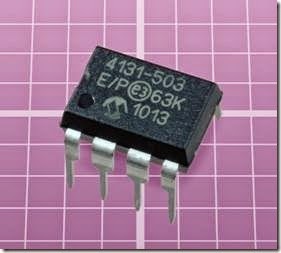
The Microchip 4131-503, shown in Figure 8-5, uses SPI protocol. It contains 128 resistors and can be powered by 1.8VDC to 5.5VDC.

The one feature that all versions of SPI have in common is that a series of high/low pulses is interpreted by the chip as a set of bits whose value defines a tap point in the resistor ladder. In computer terminology, every tap point has an ad- dress. The incoming bits define the address, after which the status of an additional input pin can tell the chip to move the wiper to that location.

Typically, there will be a chip select pin, identified as CS; a serial data input pin, identified as SDA, SI, DIN, or a similar acronym; and a serial clock pin, identified as SCL, SCLK, or SCK, which must receive a stream of pulses to which the high/low data input pulses must be synchronized. In addition, the SPI protocol allows bidirectional (duplex) serial communication. Only a minority of digital potentiometers make use of this capability, but where it exists, a serial data output pin may be labeled SDO. Alternatively, one pin may be multiplexed to enable both input and output, in which case it may be labeled SDI/SDO.

clip_image015

Figure 8-5. This digital potentiometer uses SPI protocol. See text for details.

If a pin is active-low, a bar (a horizontal line) will be printed above its acronym.

The most common type of digital potentiometer has 255 resistors and therefore 256 tap points, which have addresses numbered 0 through 255, each of which can be specified by a sequence of eight data bits constituting one byte. However, a different coding system will be applied in chips that have a different number of taps. In a 32-tap component, for instance, data is still sent in groups of eight bits, but only the first five bits define a tap address, while the remaining three are interpreted as commands to the chip.

Most 256-tap chips use an SPI protocol in which two eight-bit bytes are sent, the first being interpreted by the chip as a command, while the second specifies a tap address. Each manufacturer may use a different set of command codes, and these will vary among chips even from the same manufacturer.

Most commonly, three wires are used for data transmission and control (causing these chips to be described as 3-wire programmable potentiometers).

CS is usually, but not always, pulled low to activate the digital potentiometer for input. A series of low or high states is then applied to the data- input pin. Each time the clock input changes state (usually on the rising edge of the clock pulse) the state of the data input is copied to a shift register inside the chip. After all the bits have been clocked in, CS can change from low to high, causing the contents of the shift register to be copied into a decoder section of the chip. The first bit received becomes the most significant bit in the decoder. The value of the eight bits is de- coded, and the chip connects the W pin directly to the corresponding tap along the ladder of 255 internal resistors.

I2C Protocol

The I2C specification is controlled by NXP Semi- conductors (formerly Philips), but can be used in commercial products without paying licensing fees. Only two transmission lines are required: one carrying a clock signal, the other allowing bidirectional data transfer synchronized with the clock (although many digital potentiometers use the I2C connection only to receive data). The pins are likely to be identified by the same acronyms as the pins on a chip that uses SPI protocol.

As in SPI, a command byte is followed by a data byte, although the command set differs from that of SPI and will also differ among various I2C chips. Full implementation of I2C allows multiple devices to share a single bus, but this capability may remain unused.

Up/Down Protocol

This simpler, asynchronous protocol does not re- quire a clock input. The chip will respond to data pulses that are received at any speed (up to its maximum speed), and the pulse widths can be inconsistent.

Each pulse moves the wiper connection one step up or down the ladder. While this has the advantage of simplicity, the taps are not addressable, and consequently the wiper cannot skip to any tap without passing through intervening taps incrementally. This is not an inconvenience when the potentiometer controls audio gain, which is a primary application.

In some chips, an increment pin, usually labeled INC, receives pulses while the high or low state of a second pin, usually labeled U/D, determines whether each pulse will step the wiper up the ladder or down the ladder.

In other chips, pulses to an Up pin will step the wiper up the ladder, while pulses to a Down pin will step the wiper down the ladder.

Either of these chip designs can be referred to as a two-wire type. If an additional chip-select pin is included (labeled CS on datasheets), this type of digital potentiometer can be referred to as a three-wire type. The chip select pin is likely to be active-low, meaning that so long as it has a high state, the chip will ignore incoming signals.

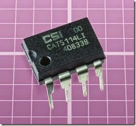
The CAT5114 shown in Figure 8-6 uses an U/D pin. It contains 31 resistors, is available in 8-pin DIP or surface-mount formats, and can be powered by 2.5VDC to 6VDC. Each of its logic inputs draws only 10µA.

In six-pin chips the INC pin is omitted, one of the H, L, or W pins will be omitted, and the U/D pin will function differently. When CS is pulled low, the chip checks the state of the U/D pin. If it is high, the chip goes into increment mode; if it is low, the chip goes into decrement mode. So long as CS remains low, each transition of the U/D pin from low to high will either increment or decrement the wiper position, depending on the mode that was sensed initially. When CS goes high, further transitions on the U/D pin will be ignored until CS goes low again, at which point the procedure repeats.
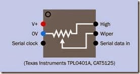
clip_image017

Figure 8-6. This digital potentiometer contains 31 resistors and uses the simplest up/down protocol to step from one tap to the next.

The chip does not provide any feedback regarding the position of its wiper, and consequently a control device such as a microcontroller cannot know the current wiper position. If the chip has nonvolatile memory (as is the case in many up/ down digital potentiometers), it will resume its previous wiper location at power-up, but here again a control device will have difficulty deter- mining what that position is. Therefore, in its basic form, an up/down chip is only appropriate for simple tasks, especially in response to up/down pushbuttons.

Other Control Systems

A few digital potentiometers use a parallel inter- face. Because they are relatively uncommon, they are not included here.

Connections and Modes

Some variants of digital potentiometers minimize the chip size and number of connections by limiting accessibility to the internal resistor lad- der. In a chip designed to function in rheostat mode, the W pin is eliminated and the chip moves an internal connection point to change the resistance between the H and L pins.

In some variants, the low end of the ladder is permanently, internally connected with ground, and the L pin is omitted. In other variants, one end of the ladder is unconnected inside the chip.

A chip designed to function in voltage divider mode will include all three pins—H, L, and W— except in some instances where the low end of the ladder is grounded internally.

Variants are shown in Figures 8-7, 8-8, 8-9, and 8-10. Because some pins may be omitted, and there is no standardization of function among the pins that do exist, circuits and chips must be examined carefully prior to use.

clip_image019

Figure 8-7. Some digital potentiometers minimize chip size and provide specialized functionality by eliminating pins. In the variant shown here, the W pin provides a volt- age between H and an internal ground connection. The chip is controlled via I2C serial protocol.

clip_image021

Figure 8-8. In this variant, the H end of the internal resistor ladder is allowed to float inside the chip, and the digital potentiometer functions as a rheostat. The chip is con- trolled via I2C serial protocol.

clip_image023

Figure 8-9. This variant provides a variable resistance be- tween the H pin and an internal connection with negative ground. Pin 5 is omitted. The chip is controlled by up/ down pulses.

clip_image025

Figure 8-10. This variant provides a variable resistance between H and L pins, without allowing either end of the resistor ladder to float. The W pin is omitted, as the wiper is tied internally to the H pin. The chips listed are con- trolled by up/down pulses.

Values

A primary limitation of digital potentiometers is that they cannot withstand significant current. This may prevent them from being substituted for an analog potentiometer unless changes are made in the circuit. H, L, and W pins are usually unable to source or sink continuous, sustained current exceeding 20mA.

Wiper resistance is the resistance that is added internally by the wiper. This is nontrivial; it is often around 100Ω, and can be as high as 200Ω.

Typical end-to-end resistance of the ladder of internal resistors may range from 1K to 100K. Val- ues of 1K, 10K, and 100K are common.

While the number of taps is likely to be a power of two in chips where the taps are addressable, up/down chips are not so constrained and may contain, for example, 100 taps.

The end-to-end resistance of a whole ladder may vary by as much as 20% from one sample of a chip to the next. Among resistor ladders in digital potentiometers sharing the same chip (i.e., in du- al or quad chips) the variation will be much smaller.

Almost all digital potentiometers are designed for a supply voltage of 5V or less. The H and L pins are not sensitive to polarity, but the voltage ap- plied to either of them must not exceed the sup- ply voltage.

How to Use It

switching. Potentiometers with this feature may include phrases such as “glitch free” in their datasheets.

Digital potentiometers that are intended primarily for audio applications often have 32 taps spaced at intervals of 2dB. This will be sufficient to satisfy most listeners.

Achieving Higher Resolution

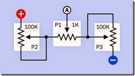
For sensitive applications where a resolution with more than 1,024 steps is required, multiple digital potentiometers with different step values can be combined. One way of doing this is shown in Figure 8-11. In this circuit, the wipers of P2 and P3 must be moved in identical steps, so that the total resistance between the positive power sup- ply and negative ground remains constant.

These two potentiometers could be contained in While most microcontrollers contain one or more analog-digital converters that change an analog input to an internal numeric value, a microcontroller cannot create an analog output. A digital potentiometer adds this functionality, although applications will be restricted by its limitation on current.

An up/down digital potentiometer can be con- trolled directly by a pair of pushbuttons, one of which will increase the resistance value while the other will reduce it. The pushbuttons must be debounced when used in this way. An alternative to pushbuttons is a rotational encoder, which emits a stream of pulses when its shaft is turned. In this case, an intermediate component (probably a microcontroller) will usually interpret the pulse stream and change it to a format that the digital potentiometer can understand.

Where a digital potentiometer is used in audio applications, it should be of the type that moves the wiper connection from one tap to another during a zero crossing of the audio signal (i.e., that is, at the moment when the AC input signal pass- es through 0V on its way from positive to negative or negative to positive). This suppresses the “click” that otherwise tends to occur during

a dual chip, and would receive identical up/down commands. P1 is at the center of the voltage divider formed by P2 and P3, and is adjusted separately to “fine tune” the output voltage that is sensed at point A.

If all three of the potentiometers in this circuit contain 100 taps, a combined total of 10,000 resistance steps will be possible.

clip_image028

Figure 8-11. If all three digital potentiometers in this schematic have 100 taps, and the wipers of P2 and P3 are moved in synchronization, the voltage measured at point A can have a high resolution of up to 10,000 steps.

What Can Go Wrong
Noise and Bad Inputs

Because a digital potentiometer is capable of receiving data at speeds as high as 1MHz, it is sensitive to brief input or power fluctuations, and can misinterpret them as instructions to move the wiper—or can misinterpret them as command codes, in a component using SPI or I2C serial protocol.

To minimize noise in the power supply, some manufacturers recommend installing a 0.1µF capacitor as close as possible to the power supply pin of the component. In addition, it is obviously important to provide clean input signals. This means thorough debouncing of any electromechanical switch or pushbutton inputs.

Wrong Chip

The wide diversity of input protocols and pinouts creates many opportunities for installation error.

Up/down, SPI, and I2C protocol require totally different pulse streams. Many manufacturers offer components that are distinguished from each other by just one or two digits in their part numbers, yet have radically different functionality.

If more than one specific type of digital potentiometer may be used during circuit development, they should be stored carefully to avoid inadvertant substitutions. Using the wrong chip may be particularly confusing in that an inappropriate input protocol will still produce some results, al- though not those which were intended.

Controller and Chip Out of Sync

As noted in the discussion of data transmission protocols, most digital potentiometers are not capable of providing feedback to confirm the position of the internal wiper. A designer may wish to include a power-up routine which establishes the state of the digital potentiometer by resetting it to a known position, at one end of its scale or the other.

Nonlinear Effects

While the end-to-end resistance of the resistor ladder inside a digital potentiometer is not likely to be affected significantly by changes in temperature, the resistance at the wiper is more heat sensitive.

In an up/down chip, there can be differential errors between incremental and decremental modes. In other words, if a tap is reached by step- ping up to it incrementally, the resistance be- tween the W pin and H or L may not be quite the same as if the same tap is reached by stepping down to it decrementally. The difference may not be significant, but may be puzzling for those who are unfamiliar with this phenomenon.

Some differences may be found among resistors in a ladder. That is, in a supposedly linear digital potentiometer, each resistor may differ in value slightly from the next.

Data Transfer Too Fast

When using a microcontroller to send data to a digital potentiometer, a small delay may be necessary between pulses, depending on the microcontroller’s clock speed. A digital potentiometer may require a minimum pulse duration of 500ns. Check the manufacturer’s datasheet for details.


digital potentiometer:What It Does,Advantages,How It Works,Variants,Volatile and Nonvolatile Memory,Taper,Data Transfer,SPI,I2C Protocol,Up/Down Protocol,Nonlinear Effects and Data Transfer Too Fast.

digital potentiometer

A digital potentiometer is also known as a digitally adjustable potentiometer, a digitally controlled potentiometer, a digitally programmed potentiometer (with acronym DPP), a digpot, or a digipot. The terms are functionally interchangeable. Because the abbreviation pot is often used to describe an analog potentiometer, some people refer to digital potentiometers colloquially as digital pots. In printed documentation, the letters in pot may be capitalized. Because it is an abbreviation, not an acronym, it is not capitalized here.

Because this component enables digital control of a variable voltage, it is a mixed signal device. It is classified here as an analog chip because it primarily emulates the function of an analog device. It may be thought of as a form of digital-analog converter, although this encyclopedia does not have a section devoted to that type of component or to analog-digital converters, as their application is relatively specialized.

What It Does

This component is an integrated circuit chip that emulates the function of an analog potentiometer. It is often described as being programmable, meaning that its internal resistance can be changed via a control input.

Digital potentiometers are particularly suited for use in conjunction with a microcontroller, which can control the internal resistance of the component. Possible applications include adjustment of the pulse width of an oscillator or multistable multivibrator (e.g., using the Control pin of a 555 timer chip); adjustment of the gain in an op-amp; specification of voltage delivered by a voltage regulator; and adjustment of a band- pass filter.

A digital potentiometer in combination with a microcontroller may also be used in conjunction with a pair of external buttons or a rotational encoder, to adjust the gain of an audio amplifier and for similar applications.

Advantages

A digital potentiometer offers significant advan- tages over an analog potentiometer:

• Reliability. The digital component may be rated for as many as a million cycles (each storing the wiper position in an internal memory location). An analog component may be capable of just a few thousand ad- justment cycles.

• Digital interface.

• Elimination of long signal paths or cable runs. The digital potentiometer can be placed close to other chips, whereas an an- alog potentiometer often has to be some distance away to enable control by the end user. Reduction in the length of signal paths can reduce capacitive effects, while elimination of cable runs will reduce manufacturing costs.

• Reduction in size and weight compared with a manual potentiometer.

A digital potentiometer also has some disadvantages:

• Its internal resistance is somewhat affected by temperature.

• It is not usually capable of passing significant current. Few chips can sink or source more than 20mA at the output, and 1mA is common. The output is primarily intended for connection with other solid-state components that have high impedance.

• Users may prefer the immediacy and tactile feel of a knob attached to an analog poten- tiometer, rather than a pair of buttons or a rotational encoder.

How It Works

A digital potentiometer changes the point at which a connection is made along a ladder of many fixed resistors connected in series inside the chip. Each end of the ladder, and each inter- section between two adjacent resistors, is known as a tap. The pin that can connect with any of the taps is referred to as the wiper, because it emu- lates the function of a wiper in an analog potentiometer. In reality, a digital potentiometer does not contain a wiper or any other moving parts.

A fully featured digital potentiometer allows access to each end of the ladder through two pins that are often labeled “high” and “low,” even though they are functionally interchangeable (except in the case of a component that simulates a logarithmic taper, as described later). The “low” end of the ladder is sometimes numbered

1. In this case, if there are n resistors, the “high” end of the ladder will be numbered n. Alternatively, if the “low” end of the ladder is numbered 1, and there are n resistors, the “high” end will be numbered n+1. This principle is illustrated in Figure 8-1.

clip_image006

Figure 8-1. Available wiper connections to a resistor lad- der inside a digital potentiometer, showing two numbering systems that may be used.

The “low” pin on a digital potentiometer may be identified as L, or A, or RL, or PA in a datasheet, while the “high” pin may be identified as H, or B, or RH, or PB and the pin that accesses the wiper is typically identified as W, or RW, or PW. Letters L, H, and W are used below. Although the L and H pins are functionally interchangeable, their labels are useful to identify which direction the W connection will move in response to an external signal.

Digital potentiometers are available with as few as 4 or as many as 1,024 taps, but common values are 32, 64, 128, or 256 taps, with 256 being the most common.

No specific schematic symbol represents a digital potentiometer. Often the component is shown as an analog potentiometer symbol inside a box that has a part number, as suggested in Figure 8-2. Control pins and the power supply may be omitted if the schematic is just intended to show logical connections. Alternatively, if the digital potentiometer is depicted in a schematic where it is connected with other components such as a microcontroller, multiple pins and functions may be included, as shown in Figure 8-3. The pins additional to L, H, and W are explained below.

clip_image008

Figure 8-2. There is no single specific symbol to represent a digital potentiometer. It may be shown using an analog potentiometer symbol in a box with a part number, as suggested here, where power connections and additional pins are omitted for clarity.

clip_image010

Figure 8-3. If a digital potentiometer appears in a schematic where it is connected with other components such as a microcontroller, additional pins and functions may be indicated. This generic representation of a digital potentiometer shows some of the functions that can be included.

Variants

A dual digital potentiometer contains two com- plete units, while a quad contains four. Triples exist but are relatively uncommon. A few chips contain six potentiometers. Multiple digital potentiometers in a chip can be used as the digital equivalent of ganged analog potentiometers, for simultaneous synchronized adjustment of multiple inputs in an audio system (two channels in a stereo amplifier, or more in a surround-sound system).

The pinouts of a sophisticated quad digital potentiometer chip are shown in Figure 8-4. Other quad chips have different pinouts and capabili- ties; there is no standardized format as there is with digital logic chips. In this example, the high/ low states of Address 0 and Address 1 select one of the four internal resistor ladders, numbered 0 through 3. The Chip Select pin makes the whole chip either active or inactive. The Write Protect pin disables writing to the internal wiper memory. The Serial Clock pin inputs a reference pulse stream to which the serial input data must be synchronized. The Hold pin pauses the chip while data is being transmitted, allowing the data transmission to be resumed subsequently. The NC pins have no connection.

Volatile and Nonvolatile Memory Any type of digital potentiometer requires memory to store its current wiper position, and this memory may be volatile or nonvolatile. Nonvolatile memory may be indicated in a datasheet by the term NV.

A digital potentiometer with volatile memory will typically reset its wiper to a center-tap position if power is disconnected and then restored. A digital potentiometer with nonvolatile memory will usually restore the most recently used wiper position, provided the chip is fully powered down and then fully powered up without glitches in the supply. If a microcontroller is being used to control the digital potentiometer, it can store the most recent resistance value in its own nonvolatile memory, in which case the type of memory in the potentiometer becomes irrelevant.

clip_image013

Figure 8-4. Pinouts of a sophisticated quad digital potentiometer chip. Other chips will have different pinouts and capabilities. This example is available in surface-mount formats only. See text for details.

Taper

Digital potentiometers are available with linear taper or logarithmic taper. In the former, each resistor in the ladder has the same value. In the latter, values are chosen so that the cumulative resistance between the wiper and the L end of the ladder increases geometrically as the wiper steps toward the H end of the ladder. This is useful in audio applications where sound intensity that increases exponentially may seem to increase linearly when perceived by the human ear.

A microcontroller can emulate logarithmic steps by skipping some taps in the ladder in a digital potentiometer, but this will result in fewer increments and lower precision.

Data Transfer

Digital potentiometers are mostly designed to use one of three serial protocols:

SPI. This acronym is derived from serial peripheral interface, a term trademarked by Motorola but now used generically. The standard is adapted in various radically different ways among digital potentiometers.

I2C. More correctly printed as I2C and properly pronounced “I squared C,” this acronym is derived from the term inter-integrated circuit. Developed by Philips in the 1990s, it is a relatively slow-speed bus-communication protocol (up to 400kbps or 1Mbps in its basic form). It is built into some microcontrollers. The standard is more uniformly and rigorously defined than SPI.

Up/down, also sometimes known as push- button or increment/decrement protocol.

Both SPI and I2C are supported by many micro- controllers, including the Atmel AVR at the heart of the Arduino.

These three systems for controlling a digital potentiometer are described in more detail in the following sections.

SPI

This is the most widely used protocol, but when reading datasheets, a lot of care must be taken to determine how it varies in each case.

The Microchip 4131-503, shown in Figure 8-5, uses SPI protocol. It contains 128 resistors and can be powered by 1.8VDC to 5.5VDC.

The one feature that all versions of SPI have in common is that a series of high/low pulses is interpreted by the chip as a set of bits whose value defines a tap point in the resistor ladder. In computer terminology, every tap point has an ad- dress. The incoming bits define the address, after which the status of an additional input pin can tell the chip to move the wiper to that location.

Typically, there will be a chip select pin, identified as CS; a serial data input pin, identified as SDA, SI, DIN, or a similar acronym; and a serial clock pin, identified as SCL, SCLK, or SCK, which must receive a stream of pulses to which the high/low data input pulses must be synchronized. In addition, the SPI protocol allows bidirectional (duplex) serial communication. Only a minority of digital potentiometers make use of this capability, but where it exists, a serial data output pin may be labeled SDO. Alternatively, one pin may be multiplexed to enable both input and output, in which case it may be labeled SDI/SDO.

clip_image015

Figure 8-5. This digital potentiometer uses SPI protocol. See text for details.

If a pin is active-low, a bar (a horizontal line) will be printed above its acronym.

The most common type of digital potentiometer has 255 resistors and therefore 256 tap points, which have addresses numbered 0 through 255, each of which can be specified by a sequence of eight data bits constituting one byte. However, a different coding system will be applied in chips that have a different number of taps. In a 32-tap component, for instance, data is still sent in groups of eight bits, but only the first five bits define a tap address, while the remaining three are interpreted as commands to the chip.

Most 256-tap chips use an SPI protocol in which two eight-bit bytes are sent, the first being interpreted by the chip as a command, while the second specifies a tap address. Each manufacturer may use a different set of command codes, and these will vary among chips even from the same manufacturer.

Most commonly, three wires are used for data transmission and control (causing these chips to be described as 3-wire programmable potentiometers).

CS is usually, but not always, pulled low to activate the digital potentiometer for input. A series of low or high states is then applied to the data- input pin. Each time the clock input changes state (usually on the rising edge of the clock pulse) the state of the data input is copied to a shift register inside the chip. After all the bits have been clocked in, CS can change from low to high, causing the contents of the shift register to be copied into a decoder section of the chip. The first bit received becomes the most significant bit in the decoder. The value of the eight bits is de- coded, and the chip connects the W pin directly to the corresponding tap along the ladder of 255 internal resistors.

I2C Protocol

The I2C specification is controlled by NXP Semi- conductors (formerly Philips), but can be used in commercial products without paying licensing fees. Only two transmission lines are required: one carrying a clock signal, the other allowing bidirectional data transfer synchronized with the clock (although many digital potentiometers use the I2C connection only to receive data). The pins are likely to be identified by the same acronyms as the pins on a chip that uses SPI protocol.

As in SPI, a command byte is followed by a data byte, although the command set differs from that of SPI and will also differ among various I2C chips. Full implementation of I2C allows multiple devices to share a single bus, but this capability may remain unused.

Up/Down Protocol

This simpler, asynchronous protocol does not re- quire a clock input. The chip will respond to data pulses that are received at any speed (up to its maximum speed), and the pulse widths can be inconsistent.

Each pulse moves the wiper connection one step up or down the ladder. While this has the advantage of simplicity, the taps are not addressable, and consequently the wiper cannot skip to any tap without passing through intervening taps incrementally. This is not an inconvenience when the potentiometer controls audio gain, which is a primary application.

In some chips, an increment pin, usually labeled INC, receives pulses while the high or low state of a second pin, usually labeled U/D, determines whether each pulse will step the wiper up the ladder or down the ladder.

In other chips, pulses to an Up pin will step the wiper up the ladder, while pulses to a Down pin will step the wiper down the ladder.

Either of these chip designs can be referred to as a two-wire type. If an additional chip-select pin is included (labeled CS on datasheets), this type of digital potentiometer can be referred to as a three-wire type. The chip select pin is likely to be active-low, meaning that so long as it has a high state, the chip will ignore incoming signals.

The CAT5114 shown in Figure 8-6 uses an U/D pin. It contains 31 resistors, is available in 8-pin DIP or surface-mount formats, and can be powered by 2.5VDC to 6VDC. Each of its logic inputs draws only 10µA.

In six-pin chips the INC pin is omitted, one of the H, L, or W pins will be omitted, and the U/D pin will function differently. When CS is pulled low, the chip checks the state of the U/D pin. If it is high, the chip goes into increment mode; if it is low, the chip goes into decrement mode. So long as CS remains low, each transition of the U/D pin from low to high will either increment or decrement the wiper position, depending on the mode that was sensed initially. When CS goes high, further transitions on the U/D pin will be ignored until CS goes low again, at which point the procedure repeats.
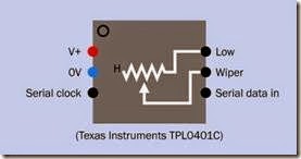
clip_image017

Figure 8-6. This digital potentiometer contains 31 resistors and uses the simplest up/down protocol to step from one tap to the next.

The chip does not provide any feedback regarding the position of its wiper, and consequently a control device such as a microcontroller cannot know the current wiper position. If the chip has nonvolatile memory (as is the case in many up/ down digital potentiometers), it will resume its previous wiper location at power-up, but here again a control device will have difficulty deter- mining what that position is. Therefore, in its basic form, an up/down chip is only appropriate for simple tasks, especially in response to up/down pushbuttons.

Other Control Systems

A few digital potentiometers use a parallel inter- face. Because they are relatively uncommon, they are not included here.
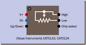
Connections and Modes

Some variants of digital potentiometers minimize the chip size and number of connections by limiting accessibility to the internal resistor lad- der. In a chip designed to function in rheostat mode, the W pin is eliminated and the chip moves an internal connection point to change the resistance between the H and L pins.

In some variants, the low end of the ladder is permanently, internally connected with ground, and the L pin is omitted. In other variants, one end of the ladder is unconnected inside the chip.

A chip designed to function in voltage divider mode will include all three pins—H, L, and W— except in some instances where the low end of the ladder is grounded internally.

Variants are shown in Figures 8-7, 8-8, 8-9, and 8-10. Because some pins may be omitted, and there is no standardization of function among the pins that do exist, circuits and chips must be examined carefully prior to use.

clip_image019

Figure 8-7. Some digital potentiometers minimize chip size and provide specialized functionality by eliminating pins. In the variant shown here, the W pin provides a volt- age between H and an internal ground connection. The chip is controlled via I2C serial protocol.

clip_image021

Figure 8-8. In this variant, the H end of the internal resistor ladder is allowed to float inside the chip, and the digital potentiometer functions as a rheostat. The chip is con- trolled via I2C serial protocol.

clip_image023

Figure 8-9. This variant provides a variable resistance be- tween the H pin and an internal connection with negative ground. Pin 5 is omitted. The chip is controlled by up/ down pulses.

clip_image025

Figure 8-10. This variant provides a variable resistance between H and L pins, without allowing either end of the resistor ladder to float. The W pin is omitted, as the wiper is tied internally to the H pin. The chips listed are con- trolled by up/down pulses.

Values

A primary limitation of digital potentiometers is that they cannot withstand significant current. This may prevent them from being substituted for an analog potentiometer unless changes are made in the circuit. H, L, and W pins are usually unable to source or sink continuous, sustained current exceeding 20mA.

Wiper resistance is the resistance that is added internally by the wiper. This is nontrivial; it is often around 100Ω, and can be as high as 200Ω.

Typical end-to-end resistance of the ladder of internal resistors may range from 1K to 100K. Val- ues of 1K, 10K, and 100K are common.

While the number of taps is likely to be a power of two in chips where the taps are addressable, up/down chips are not so constrained and may contain, for example, 100 taps.

The end-to-end resistance of a whole ladder may vary by as much as 20% from one sample of a chip to the next. Among resistor ladders in digital potentiometers sharing the same chip (i.e., in du- al or quad chips) the variation will be much smaller.

Almost all digital potentiometers are designed for a supply voltage of 5V or less. The H and L pins are not sensitive to polarity, but the voltage ap- plied to either of them must not exceed the sup- ply voltage.

How to Use It

switching. Potentiometers with this feature may include phrases such as “glitch free” in their datasheets.

Digital potentiometers that are intended primarily for audio applications often have 32 taps spaced at intervals of 2dB. This will be sufficient to satisfy most listeners.

Achieving Higher Resolution

For sensitive applications where a resolution with more than 1,024 steps is required, multiple digital potentiometers with different step values can be combined. One way of doing this is shown in Figure 8-11. In this circuit, the wipers of P2 and P3 must be moved in identical steps, so that the total resistance between the positive power sup- ply and negative ground remains constant.

These two potentiometers could be contained in While most microcontrollers contain one or more analog-digital converters that change an analog input to an internal numeric value, a microcontroller cannot create an analog output. A digital potentiometer adds this functionality, although applications will be restricted by its limitation on current.

An up/down digital potentiometer can be con- trolled directly by a pair of pushbuttons, one of which will increase the resistance value while the other will reduce it. The pushbuttons must be debounced when used in this way. An alternative to pushbuttons is a rotational encoder, which emits a stream of pulses when its shaft is turned. In this case, an intermediate component (probably a microcontroller) will usually interpret the pulse stream and change it to a format that the digital potentiometer can understand.

Where a digital potentiometer is used in audio applications, it should be of the type that moves the wiper connection from one tap to another during a zero crossing of the audio signal (i.e., that is, at the moment when the AC input signal pass- es through 0V on its way from positive to negative or negative to positive). This suppresses the “click” that otherwise tends to occur during

a dual chip, and would receive identical up/down commands. P1 is at the center of the voltage divider formed by P2 and P3, and is adjusted separately to “fine tune” the output voltage that is sensed at point A.

If all three of the potentiometers in this circuit contain 100 taps, a combined total of 10,000 resistance steps will be possible.

clip_image028

Figure 8-11. If all three digital potentiometers in this schematic have 100 taps, and the wipers of P2 and P3 are moved in synchronization, the voltage measured at point A can have a high resolution of up to 10,000 steps.

What Can Go Wrong
Noise and Bad Inputs

Because a digital potentiometer is capable of receiving data at speeds as high as 1MHz, it is sensitive to brief input or power fluctuations, and can misinterpret them as instructions to move the wiper—or can misinterpret them as command codes, in a component using SPI or I2C serial protocol.

To minimize noise in the power supply, some manufacturers recommend installing a 0.1µF capacitor as close as possible to the power supply pin of the component. In addition, it is obviously important to provide clean input signals. This means thorough debouncing of any electromechanical switch or pushbutton inputs.

Wrong Chip

The wide diversity of input protocols and pinouts creates many opportunities for installation error.

Up/down, SPI, and I2C protocol require totally different pulse streams. Many manufacturers offer components that are distinguished from each other by just one or two digits in their part numbers, yet have radically different functionality.

If more than one specific type of digital potentiometer may be used during circuit development, they should be stored carefully to avoid inadvertant substitutions. Using the wrong chip may be particularly confusing in that an inappropriate input protocol will still produce some results, al- though not those which were intended.

Controller and Chip Out of Sync

As noted in the discussion of data transmission protocols, most digital potentiometers are not capable of providing feedback to confirm the position of the internal wiper. A designer may wish to include a power-up routine which establishes the state of the digital potentiometer by resetting it to a known position, at one end of its scale or the other.

Nonlinear Effects

While the end-to-end resistance of the resistor ladder inside a digital potentiometer is not likely to be affected significantly by changes in temperature, the resistance at the wiper is more heat sensitive.

In an up/down chip, there can be differential errors between incremental and decremental modes. In other words, if a tap is reached by step- ping up to it incrementally, the resistance be- tween the W pin and H or L may not be quite the same as if the same tap is reached by stepping down to it decrementally. The difference may not be significant, but may be puzzling for those who are unfamiliar with this phenomenon.

Some differences may be found among resistors in a ladder. That is, in a supposedly linear digital potentiometer, each resistor may differ in value slightly from the next.

Data Transfer Too Fast

When using a microcontroller to send data to a digital potentiometer, a small delay may be necessary between pulses, depending on the microcontroller’s clock speed. A digital potentiometer may require a minimum pulse duration of 500ns. Check the manufacturer’s datasheet for details.


ch7 op-amp:What It Does,How It Works,Dual Inputs,Negative Feedback,Op-Amps and Comparators,Variants,Values,How to Use It,Controlling the Gain,Calculating Amplification,Unintentional DC Voltage Amplification,Low-Pass Filter and High-Pass Filter.

op-amp

Although a comparator has the same schematic symbol as an op-amp, their applications differ and they are described in separate sections of this encyclopedia.

The unabbreviated name for an op-amp is an operationalamplifier, but this term is seldom used.

What It Does

An op-amp is an operational amplifier consisting of multiple transistors packaged in an integrated circuit chip. It senses the fluctuating voltage difference between two inputs, uses power from an external supply to amplify that difference, and uses negative feedback to ensure that the output is an accurate replica of the input. Its amplification can be adjusted by changing the values of two external resistors.

Op-amps were developed originally using vacuum tubes, for use in analog computers, before the era of digital computing. Their implementation in integrated circuits dates from the late 1960s, when chips such as the LM741 were introduced (lower-noise versions of it still being widely used today). Multiple op-amps in a single package were introduced in the 1970s.

An LM741 is shown in Figure 7-1. Inside the 8-pin, DIP package is a single op-amp.

How It Works

In alternating current, voltages deviate above and below a zero value, which is sometimes referred to as the neutral value. This occurs in domestic power supplies and in audio signals, to name two very common examples. A voltage amplifier multiplies the positive and negative voltage excursions, using an external power source to achieve this. Most op-amps are voltage amplifiers.

clip_image006

Figure 7-1. The LM741, shown here, is still one of the most widely used op-amps.

An ideal amplifier maintains a linear relationship between its input and its output, meaning that the output voltage values are a constant multiple of the input voltages over a wide range. This is illustrated in Figure 7-2, where the lower curve is a duplicate of the upper curve, the only difference being that its amplitude is multiplied by a fixed amount (usually much greater than shown here). The ratio is properly known as the gain of the amplifier, usually represented with letter A (for amplification).

clip_image008

Figure 7-2. In an ideal voltage amplifier, the output volt- age will be a duplicate of the fluctuating input voltage, the only difference being that the amplitude of the output is multiplied by a fixed amount. This ratio is known as the gain of the amplifier.

Figure 7-3 shows the triangular symbol for a generic single-input amplifier (not an op-amp). It may contain any number of components. The triangle almost always points from left to right, with its input on the left and its output on the right, and power attached above and below. This is often a dual voltage power supply, which is convenient for amplifying a signal that fluctuates above and below 0V. In some schematics, the power supply connections may not be shown, as they are assumed to exist.

clip_image010

Figure 7-3. The generic symbol for a single-input amplifier (not an op-amp), with the positive side of its power supply being equal and opposite in value to the negative side, and 0V being at the midpoint between them.

• While the blue negative symbol is generally used throughout this encyclopedia to indicate 0V ground, it represents a voltage identified as V− in a dual voltage power supply, being equal in value but opposite in polarity to the positive side of the supply, V+. (Some- times these voltages are indicated as V− and V+.) The output from this imaginary generic amplifier is shown in the figure as a linear amplification of the input.

Dual Inputs

An op-amp has two inputs instead of one, and amplifies the voltage difference between them. Its symbol is shown in Figure 7-4. The upper input in this figure is held at 0V, midway between V+ and V−. Because the op-amp has so much gain, an accurate reproduction of its input would cre- ate an output exceeding the voltage of the power supply. Because this is not possible, the output tends to become saturated and consequently is clipped when it reaches its maximum value, as shown in the figure. The thumbnail graphs give only an approximate impression, as they are not drawn to the same scale.

clip_image012

Figure 7-4. An op-amp has so much gain, its output will tend to saturate, producing a square wave regardless of the shape of the input.

The small black plus and minus signs alongside the two inputs to the op-amp have nothing to do with the voltage supplied to the component. The “minus” input is properly referred to as the inverting input while the “plus” input is the noninverting input, in recognition of their functions.

The inputs are sometimes arranged with the mi- nus above the plus, and sometimes with the plus above the minus. Schematics should be inspected carefully to note which arrangement is being used.

The positive and negative power connections to the op-amp may be omitted, but if shown, they always place V+ at the top, regardless of which way around the inputs are presented.

If a signal is applied to the noninverting input, while the inverting input is held at 0V ground, the op-amp provides an output in which the voltage is not inverted relative to the input.

If the input connections are swapped, so that the inverting input receives the incoming signal while the noninverting input is tied to 0V ground, the output from the op-amp is inverted (the gain remains the same). See Figure 7-5.

clip_image014Figure 7-5. When the incoming signal is applied to the in- verting input of an op-amp while its noninverting input is held at 0V ground, the output is inverted.

• An op-amp that is being used without any other components to moderate its output is functioning in open loop mode.

Negative Feedback

To create an output that is an accurate replica of the input, the op-amp must be brought under control with negative feedback to the input sig- nal. This is illustrated in Figure 7-6. A resistor connects the output back to the inverting input, so that the input is automatically reduced to the point where the output is no longer saturated. The values of R1 and R2 will determine the gain of the op-amp, as explained in “How to Use It” on page 53. The op-amp is now functioning in its in- tended closed loop mode, meaning that the out- put is being tapped for feedback.

To obtain a linear output that is noninverted, connections are made as shown in Figure 7-7. The resistors form a voltage divider between the output and 0V ground, effectively increasing the comparison value on the inverting input.

clip_image016

Figure 7-6. A resistor applies negative feedback to the in- verting input of an op-amp, and creates a linear output.

clip_image018

Figure 7-7. Where the incoming signal is applied to the noninverting input, negative feedback is created by using a pair of resistors forming a voltage divider between the output and 0V ground.

• Note that the gain of an op-amp is specific to a particular frequency range of AC signal. This is discussed in “How to Use It” on page 53.

Op-Amps and Comparators

A comparator can be regarded as a type of op- amp, and in fact an op-amp can be used as a comparator, comparing a variable DC voltage on one input with a reference voltage on another input. However, the two types of components have diverged in design to the point where they should be considered separately. The distinction is sufficiently important to have prompted Texas Instruments to issue an Application Report in 2001 titled “Op Amp and Comparators—Don’t Confuse Them!”.

Differences in function are summarized in the previous entry discussing comparators (see “Dif- ferences from an Op-Amp” on page 42).

Variants

Because op-amps are mostly low-current devices, they are widely available in very small surface-mount formats, in addition to the through-hole DIP packages which used to be more common.

Many chips are available containing two or more op-amps. This is often expressed as the number of channels in the component. A dual chip contains two op-amps, while a quad chip contains four op-amps. Usually all the op-amps in a chip share the same power supply. Bipolar or CMOS transistors may be used.

Because op-amps are widely available in dual and quad packages, it’s quite common for a circuit designer to have one op-amp in a chip “left over.” The designer may be tempted to use that spare unit as a comparator instead of installing an additional chip. To address this situation, some manufacturers offer hybrid op-amp chips containing an additional comparator. The Texas Instruments TLV2303 and TLV2304 are examples.

Values

The op-amps derived from 1970s designs often tolerate a wide range of power-supply voltages. Plus-or-minus 5VDC to plus-or-minus 15VDC is a common range. Modern op-amps are available that run from as little as 1VDC to as much as 1,000VDC.

Op-amps are available for frequencies ranging from 5KHz all the way up to 1GHz.

A “classic” op-amp such as the LM741, which is still widely used, will operate with a power supply ranging from plus-or-minus 5VDC to plus-or- minus 22VDC. Its output is rated for up to 25mA, and its input impedance is at least 2MΩ. The most current it will draw from an input is around 0.5µA.

VIO is the input offset voltage. In an ideal compo- understanding of the complexities of mathematics describing alternating current, which are not included this encyclopedia. Almost all the appli- cations have a common starting point, however, which is to establish and control the gain of the feedback circuit.

Controlling the Gain

nent, the output from an op-amp should be 0V

when its inputs have a voltage difference of 0V.

"AVOL

is the open-loop voltage gain, defined as the

In practice, the output will be 0V when the inputs differ by the offset voltage. VIO is likely to be no greater than a couple of mV, and negative feed- back can compensate for the offset.

VICR is the common mode voltage range. This is the range of input voltages that the op-amp will tolerate. This can never be more than the positive power supply voltage and will often be less, de- pending on the types of transistors that are used on the input side. If an input voltage goes outside the common mode voltage range, the op-amp will stop functioning.

VIDR is the input differential voltage range—the maximum permissible difference between peak positive and peak negative input voltages. This is often expressed as plus-or-minus the power supply voltage, or slightly less. Exceeding the range can have destructive consequences.

IB is the input bias current, averaged over the two inputs. Most op-amps have extremely high input impedance and consequently use very low input currents.

Slew rate at unity gain is the rate of change of the output voltage caused by an instantaneous change on the input side, when the output of the op-amp is connected directly back to the inverting input (during operation in noninverting mode).

How to Use It

In addition to being an amplifier for AC signals, an op-amp can serve as an oscillator, filter, signal conditioner, actuator driver, current source, and voltage source. Many applications require some

maximum voltage amplification that can be

achieved when no feedback is applied from the output to an input. This remains constant until the AC frequency rises to a point known as the breakover frequency. If the frequency continues to rise, the maximum gain diminishes quite rap- idly, until finally it terminates in 1:1 amplification at the unity gain frequency. This transition is shown by the orange line in Figure 7-8. The length of each purple line shows the frequencies which can be tolerated when the op-amp is used in closed-loop mode, and a negative feedback loop limits the gain. For example, where the gain is just 10:1, it can remain constant to just above 10KHz.

Note that both of the scales in this graph are log- arithmic.

Calculating Amplification

So long as an op-amp is used within the bound- aries of the graph, its voltage amplification can be controlled by choosing appropriate feedback and input resistors. If the op-amp is being used in noninverting mode, and R1 and R2 are placed as shown in Figure 7-7, the amplification ratio, A, is found approximately by the formula:

A = (approximately) 1 + (R2 / R1)

From this it can be seen that when R1 is very large compared with R2, the gain diminishes to near unity. If R1 becomes infinite and R2 is zero, the gain is exactly 1:1. This can be achieved by re- placing R2 with a section of wire (theoretically of zero resistance) and omitting R1 entirely, as in Figure 7-9. In this configuration, the output from the op-amp should be identical with its input.

clip_image020

Figure 7-8. Where each horizontal purple line meets the diagonal orange line, this is the maximum frequency that can be used without reduction in the maximum gain of an op-amp.

clip_image022

Figure 7-9. While an op-amp is in noninverting mode, if the feedback resistor is replaced with a section of wire and the 0V ground connection is omitted entirely, the gain of the op-amp diminishes theoretically to 1:1.

If the op-amp is being used in inverting mode, and R1 and R2 are placed as shown in Figure 7-6, then the voltage amplification ratio, A, is found approximately by the formula:

A = (approximately) −(R2 / R1)

• Note the minus sign. In inverting mode, gain is expressed as a negative number.

• In a practical circuit, at the expected fre- quency, the amplification factor established by choice of resistors should be no more than 20.

• An inverting circuit has a relatively low input impedance. For this reason, in most applica- tions, a noninverting circuit is preferred.

Unintentional DC Voltage Amplification

Although the op-amp is intended primarily as an AC signal voltage amplifier, it will also amplify a DC difference between the voltages on its inputs. In the upper section of Figure 7-10, a positive DC offset is inverted and amplified to the point where the output is forced to its negative limit, and the signal is lost, because its fluctuations have been overwhelmed by the positive offset. A coupling capacitor (shown in the lower section of the figure) removes the DC voltage while pass- ing the AC signal. The appropriate capacitor val- ue will depend on the frequency of the signal.

Low-Pass Filter

An op-amp can facilitate a very simple low-pass audio filter, just by adding a capacitor to the basic inverting circuit previously shown in Figure 7-6. The filter schematic is shown in Figure 7-11. Capacitor C1 is chosen with a value that passes higher audio frequencies and blocks lower audio frequencies. Because the gain of the basic invert- ing circuit is approximately −(R2 / R1), the op- amp functions normally when the impedance of C1 is blocking the low frequencies, forcing them to pass through R2. Higher frequencies, however, are able to bypass R2 through C1, lowering the effective resistance of the feedback section of the circuit, thus reducing its gain. This way, the power of the op-amp is greatly reduced for higher frequencies compared with lower frequencies. A passive RC circuit could achieve the same effect, but would attenuate the signal, while the op- amp circuit boosts part of it.

clip_image024

Figure 7-10. The addition of a capacitor at the input of an op-amp is often necessary to prevent any DC voltage off- set being amplified. In the upper section of this figure, a DC offset is large enough to force the inverted output to its negative limit, and the signal is completely lost.

clip_image026

Figure 7-11. A very basic low-pass filter, which works by allowing capacitor C1 to bypass resistor R2 at higher au- dio frequencies.

High-Pass Filter

A simple high-pass filter can be created by adding a capacitor to the basic noninverting circuit previously shown in Figure 7-7. The filter schematic is shown in Figure 7-12. Once again capacitor C1 is chosen with a value that passes higher audio frequencies and blocks lower audio frequencies. Because the gain of the basic non- inverting circuit is approximately 1 + (R2 / R1), the op-amp functions normally when the impedance of C1 is blocking the low frequencies, forcing them to pass through R1. Higher frequencies, however, are able to bypass R1 through C1, lowering the effective resistance of that section of the circuit, thus reducing the negative feedback and increasing the gain. This way, the power of the op-amp is increased for higher frequencies compared with lower frequencies. A passive RC circuit could achieve the same effect, but would attenuate the signal, while the op-amp circuit boosts part of it.

clip_image028

Figure 7-12. A very basic high-pass filter, which works by allowing capacitor C1 to bypass resistor R1 at higher audio frequencies.

Relaxation Oscillator

The schematic in Figure 7-13 is similar to the circuit shown in Figure 6-12 using a comparator. It functions as a relaxation oscillator, which is a form of astable multivibrator. The lower half of the circuit is a positive feedback loop that reinforces the output while the upper half of the circuit is charging the capacitor. Eventually the charge on the capacitor exceeds the voltage on the noninverting input of the op-amp, creating negative feed- back that exceeds the positive feedback. The capacitor discharges and the cycle repeats. The component values in the figure should generate an output that runs at around 2Hz. Reducing the value of the capacitor will increase the frequency.

Single Power Source

A few op-amps are designed to work from single voltages, but they are a relatively small minority, and will clip the output signal if the input goes negative. Power supplies are readily available that provide multiple voltages such as +15VDC, 0V, and -15VDC. They are ideal for driving an op- amp—but may not be useful for any other com- ponents in the circuit. Can an op-amp that is de- signed for dual voltages be made to run from a single supply, such as 30VDC?

clip_image030

Figure 7-13. A relaxation oscillator.

This is relatively easy to do. The op-amp simply needs a potential difference to power its internal transistors, and 30VDC on the V+ pin with 0VDC on the V− pin will work just as well as +15VDC and -15VDC. However, referring back to Figure 7-6, if the op-amp is used in inverting mode, an intermediate voltage must be supplied to the noninverting input. Likewise, in noninverting mode, an intermediate voltage is necessary for one of the inputs, and must be half-way

between the extremes of the power supply. If the supply is +15VDC and -15VDC, the midpoint is 0V. If the supply is 30VDC and 0V, the midpoint is 15VDC.

Because the inputs of an op-amp have a very high impedance and draw negligible current, the intermediate voltage can be provided with a simple voltage divider, as shown in Figure 7-14, where R3 and R4 should be no greater than 100K each. Their exact values are not important, so long as they are equal.

clip_image032

Figure 7-14. A voltage divider, comprised of R3 and R4 in this schematic, can provide a voltage halfway between V+ and negative ground, enabling the op-amp to use just one power supply instead of two.

A coupling capacitor should still be used on the input side, as shown, because there is no guarantee that the input signal will be centered precisely on 15V, and any offset will be amplified, potentially causing clipping of the signal. For similar reasons, a coupling capacitor is also added on the output side.

Offset Null Adjustment

Some op-amps provide two pins for offset null adjustment, which is a setup process to ensure that identical voltage on the two inputs will pro- duce a null output. This is a way of compensating for any internal inconsistencies introduced during the manufacturing process.

To perform offset null adjustment, both input pins are connected directly to 0V ground, and the ends of a trimmer potentiometer (typically, 10K) are connected with the offset null pins, while the wiper of the potentiometer is centered and then connected with the negative power supply. The probes of a meter that is set to measure DC volts are placed between the output of the op-amp and 0V ground. The potentiometer is then ad- justed until the meter shows a reading of 0VDC. A schematic is shown in Figure 7-15.

clip_image034

Figure 7-15. Connections for making an offset null adjust- ment to an op-amp that allows this procedure.

What Can Go Wrong
Power Supply Problems

Op-amps are especially vulnerable to reversed polarity in a power supply. If there is even a re- mote possibility of this occurring, a diode in series with one side of the supply can provide pro- tection.

A more realistic concern is the destructive con- sequence of an input signal that exceeds the power supply voltage(s) of the op-amp. Even if the input is within the acceptable range, it can still cause permanent damage if it is applied be- fore the op-amp powers up.

Bad Connection of Unused Sections

Multiple op-amps are often combined in a single package. If some of these “sections” remain un- used, they will still receive power from the shared supply, and will attempt to function. If the inputs are left unconnected, they will pick up small stray voltages by capacitance or induction, and in the absence of negative feedback, the op-amp will create unpredictable outputs, consuming power and possibly interacting with other sections of the same chip. Figure 7-16 shows three incorrect options for addressing this problem, and one recommended option (derived from Texas In- struments Application Report SLOA067).

clip_image036

Figure 7-16. When multiple op-amps share a chip, one that is unused will still receive power from the shared sup- ply. Its inputs must not be allowed to float, and must be connected to minimize activity and power consumption. Three common errors are shown here, with one recommended option. Note the distinction between 0V ground (0V) and negative power (V−).

Oscillating Output

The inputs of an op-amp are vulnerable to stray electromagnetic fields. If the conductors leading to and from the op-amp are relatively long, the output can couple capacitively with the input during voltage transitions, causing unwanted oscillations.

The commonly recommended solution to this problem is to add a 1µF bypass capacitor be- tween the power supply and 0V ground. How- ever, some manufacturers recommend alternatives such as introducing a very small amount of hysteresis, or reducing the value of input resistors to below 10K.

Confused Inputs

A schematic may show an op-amp with the non- inverting input above the inverting input, or vice versa. The only indication of this will be the plus and minus signs inside the chip, which can be extremely small and easily overlooked. For convenience in drawing a diagram, two op-amps in the same circuit may have their inputs shown in opposite configurations. Special care must be taken to verify that the inverting and noninverting input pins on a chip are correctly assigned.


comparator:What It Does,Hysteresis,How It Works,Differences from an Op-Amp,Variants,Values,How to Use It,AND gate,Bistable Multivibrator,Relaxation Oscillator,Level Shifter and Window Comparator.

comparator

Although a comparator has the same schematic symbol as an op-amp, their applications differ and they are described in separate sections of this encyclopedia.

This entry describes an analog comparator. A digital comparator is very different, being a logic chip that compares two binary numbers that can be referred to as A and B. Outputs from the chip indicate whether A>B or A<B or A=B. The digital comparator does not have an entry in this encyclopedia.

What It Does

A comparator is an integrated circuit chip that compares a variable voltage on one input pin with a fixed, reference voltage on a second input pin. Depending which voltage is higher, the out- put from the comparator will be high or low.

The output will make a clean transition between two fixed values, even if the input is infinitely variable. Thus the comparator can function as an analog-digital converter, as shown in Figure 6-1.

Because the output voltage range can be adjusted up or down independently of the input range, a comparator can also function as a volt- age converter.

Hysteresis

If positive feedback is added through external resistors, hysteresis can be introduced. We may imagine a hysteresis zone extending above and below the reference voltage level. Small input variations that occur within the zone will be ignored. The comparator only reacts when the in- put signal emerges above or below the hysteresis zone. When the input signal returns into the hysteresis zone, this event also will be ignored. The concept is illustrated graphically in Figure 6-2. A circuit to create hysteresis is shown in Figure 6-10.

How It Works

The schematic symbol for a comparator is shown in Figure 6-3. This seems identical to the symbol for an op-amp, described in Chapter 7, but an op- amp is traditionally a dual-voltage device using positive and negative power sources that are equal and opposite, in addition to a zero value midway between the two. Modern comparators mostly use a conventional single voltage, and therefore the negative symbol used in comparator schematics throughout this section of the en- cyclopedia represents 0 volts. It has the same meaning as the ground symbol found in many schematics elsewhere.

The two inputs to a comparator are described as inverting and noninverting (for reasons explained later). Confusingly, these are identified with plus and minus symbols inside the triangle that rep- resents the component. These plain black-and-

white symbols have nothing to do with the power supply.

clip_image006

Figure 6-1. The basic behavior of a simple comparator is shown here.

Often, in schematics, the power supply is not shown, because it is assumed to be present. However, all comparators require a power supply in order to function.

The basic internal and external connections used in conjunction with a typical comparator are shown in Figure 6-4.

The potentiometer at top left is often a trimmer, to fine-tune a reference voltage. The variable in- put can come from a sensor or any other device capable of delivering a voltage up to the limit set by V1.

The output is often an open collector from an internal bipolar transistor, as shown in the figure.

Note that as many as three different voltages can be used, as indicated by the different colors associated with V1, V2, and V3. However, they must share a common ground to enable the comparator to make valid comparisons.

When the noninverting input exceeds the volt- age of the inverting input, the output transistor goes into its “off” state, and blocks current from an external pullup resistor. Because the current from the resistor now has nowhere else to go, it is available to drive other devices attached to the comparator output, and the output appears to be high.

clip_image008

Figure 6-2. The performance of a comparator shown in the previous figure can be modified by the addition of hysteresis. Small variations that occur within the hysteresis zone are ignored.

When the noninverting input falls below the voltage of the inverting input, the transistor be- comes conductive, and sinks almost all the cur- rent from the pullup resistor, assuming other de- vices attached to the output have a relatively high impedance. The output from the comparator now appears to be low.

This can be summed up as follows:

• When a variable voltage is applied to the noninverting input, and it rises above the reference voltage applied to the inverting in- put, the output transistor turns off, and the comparator delivers a high output.

• When a variable voltage is applied to the noninverting input, and it falls below the ref- erence voltage applied to the inverting in- put, the output transistor turns on, and the comparator delivers a low output.

clip_image010

Figure 6-3. The symbol for a comparator is the same as the symbol for an op-amp, even though they often require different types of power supply and their functions are sig- nificantly different.

clip_image012

Figure 6-4. Connections to a comparator, and their functions.

If the reference voltage and the variable voltage are swapped between the input pins, the behavior of the comparator is reversed. This relation- ship is illustrated in Figure 6-5. When a voltage transition is applied to the inverting input, the transition is inverted at the output.

clip_image014

Figure 6-5. Depending which input pin is used for the reference voltage, and which input carries a variable voltage, the comparator output either follows the variable voltage or inverts it.

Placement of the plus and minus signs inside the comparator symbol may vary. Most often, the minus sign is above the plus sign, as shown in all the schematics here. Sometimes, however, for convenience in drawing a schematic, the plus sign may be shown above the minus sign. Regardless of their placement, the plus sign always identifies the noninverting input, and the minus sign always identifies the inverting input. To avoid misinterpretations, schematics should be inspected carefully.

Where a power supply for the comparator is shown, the positive side is always attached to the upper edge of the symbol, while 0V ground is always attached to the lower edge.

Differences from an Op-Amp

Saturation versus linearity

The output of a comparator is optimized for saturation (high or low, without intermedi- ate levels, using positive feedback). The out- put of an op-amp is optimized for linearity (faithful reproduction of nuances in the in- put, using negative feedback).

Output mode

The majority of comparators have open- collector outputs (or open-drain outputs in CMOS devices) where the voltage is established by a pullup resistor. This can be adjusted for compatibility with other components, especially 5VDC logic. Only a minority have push-pull amplifier outputs that re- quire no pullup resistor. By comparison, among op-amps, a push-pull output that functions as a voltage source is the tradition- al default.

Faster response

A comparator responds more quickly than an op-amp to changes in input voltage, if the op-amp is used in the role of a comparator. The comparator is primarily a switching de- vice, not an amplifier.

Hysteresis

This is generally desirable in a comparator, for reasons already explained, and some components are designed with hysteresis built in. This feature is undesirable in an op- amp, as it degrades sensitivity.

Open-loop operation

(i.e., without feedback) this can be used with a comparator. An op-amp is intended for use in closed-loop circuits (i.e., with feedback), and manufacturers will not specify its per- formance in an open loop.

As previously noted, a comparator usually re- quires a single-voltage power supply, while an op-amp often requires a dual-voltage power supply.

Variants

Where a comparator uses a MOSFET output transistor, it may have an open-drain output, which requires a pullup resistor, as with an open- collector output.

Some comparators have a push-pull output, capable of supplying output current (usually a small amount). In these instances, no pullup resistor is necessary or desirable. The output volt- age range will be closest to rail-to-rail values (i.e., the range of the power supply) where MOSFETs are used for the output, as MOSFETs impose a smaller voltage drop than bipolar transistors.

The advantage of an open collector (or open drain) relative to a push-pull output is that it al- lows the output voltage to be set independently of the power supply voltage. Another advantage is that multiple outputs can be connected in parallel, as in a window comparator circuit (described below).

Some comparators incorporate a reference volt- age on the chip, based on the power supply to the chip. In this case, a separate reference voltage does not have to be supplied, and the component will draw less current.

Many chips are available containing two or more comparators. This is often expressed as the number of channels in the component. A dual comparator typically allows two different voltage sources for the outputs of the comparators. They will share the same 0V ground, however. Chips such as the LM139 and LM339 contain four comparators, and are available in through-hole or surface-mount formats. They have become a generic choice, costing less than $1 apiece.

An LM339 comparator chip is shown in Figure 6-6. This is a quad chip, meaning that it contains four comparators. They share a common power supply. The chip is TTL and CMOS compatible, is typically powered by 5VDC, but can be driven by up to 36VDC. The input differ- ential voltage range also extends up to 36V.

clip_image017

Figure 6-6. The LM339 quad comparator chip, shown here, was introduced long ago but remains widely used.

Some comparators have an internal latch function that is accessed by a dedicated pin. The latch-enable signal forces the comparator to assess its inputs and hold an appropriate output which can then be checked by other components.

Values

In a datasheet, VIO (also referred to as VOS) is the input offset voltage. This is a small voltage, in addition to the reference voltage, which the comparator will require to toggle its output in either direction, up or down. Figure 6-7 shows this graphically. VIO sets the limit of resolution of the comparator, which will not respond unless the input voltage exceeds the reference voltage by this amount. A smaller value for VIO is better than a larger value. Common values for VIO range from 1mV to 15mV. The actual offset voltage tends to vary between one sample of a component and another. VIO is the maximum allowed value for a component.

Because the comparator will not respond until the reference voltage is exceeded by VIO, the out- put pulse width will be narrower than if the comparator reacted at the point where the variable voltage input was precisely the same as the reference voltage.

clip_image019

Figure 6-7. The input offset voltage is the very small volt- age that a comparator requires, additional to the reference input voltage, before it will toggle its output from low to high or high to low.

VTRIP+ and VTRIP- are the rising and falling voltages, respectively, that will trip the comparator out- put where the comparator exhibits some innate hysteresis without an external feedback loop. They are also referred to as Lower State Transition Voltage (LSTV) and Upper State Transition Volt- age (USTV).

VHYST is the hysteresis range defined as VTRIP+ mi- nus VTRIP-. The relationship is shown graphically in Figure 6-8.

AVD is the voltage gain of a comparator, in which the letter “A” can be thought of as meaning “am- plification.” The gain is measured as a maximum ratio of output voltage to input voltage. Typically it ranges from 40 to 200.

Supply voltage for modern comparators is often low, as the components are used in surface- mount format for battery-powered devices where low power consumption is a primary concern. Thus, 3VDC is common as a power requirement, and 1.5VDC comparators are available. Still, older chips can use as much as 35VDC.

clip_image021

Figure 6-8. The value of VTRIP shows the hysteresis in a comparator—the range of input voltages, relative to the reference voltage, in which it will not respond.

Supply current can range from 7mA down to be- low 1µA.

ISINK is the recommended typical or maximum sink current that the component will tolerate, if it has an open-collector output. This value should be considered in relation to the power dissipation, PD.

The propagation delay in a comparator is measured from the moment when an input (usually a square wave) reaches the triggering value, to the time when the consequent output reaches 50% of its final value.

When a comparator is driving CMOS logic using a 5VDC power supply, a typical value for a pullup resistor is 100K. It does not have to be lower, be- cause CMOS has such a high input impedance.

How to Use It

In Figure 6-1, a hypothetical comparator responds immediately when the input voltage equals the reference voltage value. However, this is an idealized scenario. A magnified view, in Figure 6-9, suggests that the comparator is likely to respond with jitter when the input signal is very close to the reference voltage, because of tiny variations in heat, current, and other variables. This jitter will cause significant problems if the comparator is driving a device such as a relay, directly or indirectly.

Hysteresis eliminates this uncertainty around the transition level of the input, by telling the comparator to ignore small irregularities in the input voltage. Hysteresis is also useful in many situations where larger variations in a sensor input should be ignored. In Figure 6-2, for instance, suppose that the input voltage comes from a temperature sensor. The small bump in the right- hand section of the curve is probably unimportant; it could be caused by someone opening a door, or a person’s body heat in brief proximity to the sensor. There’s no point in responding to every little event of this type. In this application, the larger, longer-term temperature trend is what matters, and significant hysteresis is appropriate.

Also, if a comparator is being used as a thermo- stat, to switch a heating system on and off, we do not want the comparator to respond as soon as the temperature rises just a small amount. The heating system should run for a while before it elevates the temperature beyond the hysteresis zone.

The usual way to create hysteresis is with positive feedback. In Figure 6-10, a connection from the output of the comparator runs back through a 1M potentiometer to the variable (noninverting) input. The effect that this has is to reinforce the input voltage with the output voltage, as soon as the comparator input goes high. Now the input can diminish slightly without switching off the comparator. But if the input declines significant-

ly, even the feedback from the output voltage won’t be sufficient to maintain the variable input at a higher level than the reference voltage. (Re- member, the “high” output voltage from the comparator is a fixed value; it does not change in proportion with the input voltage.) Consequently, the output toggles to low. Now the variable input is deprived of help from the comparator output, so it will be low enough that it has to rise considerably to toggle the comparator back on again. During that period, once again, small variations will be ignored.

clip_image023

Figure 6-9. In real-world applications, tiny variations where the variable input voltage crosses the reference voltage can induce jitter in the output from a comparator that has no hysteresis.

In the schematic, a phototransistor (PT1, at left) is in series with a 3.3K resistor to adjust its voltage output to a suitable range. A 1M potentiometer at upper-left is wired as a voltage divider, so that it can establish a reference level that matches the light level that we wish to detect with the pho- totransistor.

clip_image025

Figure 6-10. A simple circuit to achieve hysteresis with positive feedback to the variable input of a comparator.

The 470Ω resistor is the pullup resistor, which protects the LED from excessive current. The lower 1M resistor adjusts the amount of positive feedback, which determines the width of the hysteresis zone.

Values for components may have to be adjusted depending on the supply voltage, the variable input voltage, and other factors. But the principle will remain the same. Note that in the example shown, all the positive voltage sources are identical. In practice, different voltages could be used, so long as they share a common ground.

AND gate

A set of open-collector comparators can function jointly as an AND gate, when their outputs are tied together with one pullup resistor. So long as all the output transistors are nonconductive, the output will be high. If just one comparator toggles into conductive mode, the output will be low. See Figure 6-11.

clip_image027

Figure 6-11. If the outputs of multiple open-collector comparators are tied together with a suitable pullup resistor, they will function as an AND gate.

Bistable Multivibrator

If positive feedback to the noninverting input of the comparator is sufficiently high, a voltage al- most at 0V ground will be required to counter the high output from the comparator—after which, a voltage almost equal to the supply voltage will be needed to turn it back on. In other words, the comparator is behaving like a bistable multivi- brator, or flip-flop.

Relaxation Oscillator

A relaxation oscillator, which is a form of astable multivibrator, can be created using direct positive feedback in combination with delayed negative feedback. In Figure 6-12, positive feedback goes to the noninverting input, as before, but negative feedback also passes through a 220K resistor to the inverting input of the comparator. A 0.47µF capacitor initially holds the inverting input low, while the capacitor charges. Gradually the ca- pacitor reaches and exceeds the charge on the noninverting input, so the output from the com- parator toggles to its low state. This means that its internal transistor is now sinking current, and it discharges the capacitor. Because the noninverting input is being held at a voltage midway between supply and ground by the two 100K re-

sistors forming a voltage divider, eventually the voltage on the inverting input controlled by the capacitor falls below the noninverting voltage, so the cycle begins again.

clip_image029

Figure 6-12. A comparator can be used to create a relaxation oscillator.

Level Shifter

Where a comparator is used simply to change the level of an input voltage, it can be referred to as a level shifter. An example of a level shifter is shown in Figure 6-13, in which a high/low 3VDC logic input is converted to a high/low logic out- put at 5VDC.

Window Comparator

A window comparator is a circuit (not a single component) that will respond to input voltages that deviate outside an acceptable “window” of values. In other words, the circuit responds any- time the variable input is either unacceptably low or unacceptably high.

An example could be an alarm that will sound if a temperature is either too low or too high. In Figure 6-14, two comparators are used to create a window comparator circuit, both sharing a variable voltage input from a sensor. A voltage divider is necessary to establish a higher voltage limit at the noninverting input of the upper com-

parator, while a separate voltage divider would establish a lower limit at the inverting input of the lower comparator. If an alarm has an appropriate resistance, it can be used instead of a pull- up resistor. The alarm will sound when the output from either comparator is low, which happens if the inverting input has a higher voltage than the non-inverting input.

clip_image031

Figure 6-13. A comparator can be used to convert high

clip_image033

Figure 6-14. A basic, simplified circuit for a window comparator. See text for details.

A continuous converter changes its output promptly in response to a change in input. This requires continuous current consumption. Be- cause many applications only need to check the output from a comparator at intervals, power can be saved by using a clocked or latched comparator.

What Can Go Wrong

and low 3V logic inputs into high and low 5V logic outputs.

Other Applications

As previously noted, a comparator can be used as a simple analog-digital converter. It has “one bit” accuracy (i.e., its output is either high or low).

A comparator can be used as a zero point finder when its variable voltage input is attached to an AC signal. The output from the comparator will be toggled whenever the AC signal passes through zero volts. The output will be a square wave (approximately) instead of a sine wave.

Oscillating Output

The high input impedance of a comparator is vulnerable to stray electromagnetic fields. If the conductors leading to and from the comparator are relatively long, the output can couple capacitively with the input during voltage transitions, causing unwanted oscillations.

The commonly recommended solution to this problem is to add 1µF bypass capacitors to the power supply on either side of the comparator. However, some manufacturers recommend alternatives such as introducing just a small amount of hysteresis, or reducing the value of input resistors to below 10K.

If a chip contains multiple comparators, and one of them is unused, one of its input pins should be tied to the positive side of the voltage supply while the other should be tied to 0V ground, to eliminate the possibility of an oscillating output.

Confused Inputs

A comparator will function if its two inputs are swapped accidentally, but its high and low out- put states will be the inverse of what is expected. Also, if positive feedback is used, transposed in- puts can create oscillations. Because the comparator symbol may appear in a schematic with the noninverting input either below or above the inverting input, the inputs are easily transposed by accident.

One way to remember which way the inputs should be connected is to use the mnemonic: “plus, high, positive.” The plus input creates a high output when the input becomes more positive than the reference voltage on the other input. The opposite is less intuitively obvious: the mi- nus input creates a high output when the input becomes more negative than the reference volt- age on the other input.

Wrong Chip Type

Different comparators offer different outputs: open collector, open drain, and push-pull. While open collector and open drain function similarly, the pullup resistor value is likely to be different in each case. If a push-pull output is mistakenly connected as if it is open collector or open drain, it will not work correctly, if at all. Different types of comparators must be sorted and stored in clearly labeled bins.

Omitted Pullup Resistor

It is relatively easy to forget to include the pullup resistor on an open-collector output. In this case, when the transistor inside the comparator is in its nonconductive state, the output pin will be floating, with an indeterminate voltage that will create confusing or random results.

CMOS Issues

As usual when using CMOS chips, it is bad practice to allow unconnected, floating inputs. This is an issue where a chip contains multiple comparators, some of which are not being used. The solution recommended by some manufacturers is to tie one input of an unused comparator to the supply voltage, and the other input of the same comparator to ground.

Erratic Output

If positive feedback is insufficient, the comparator output may show signs of jitter. Conversely, if the positive feedback is excessive, the comparator may get stuck in an on state or an off state. Feedback must be chosen carefully.

Swapped Voltages

A comparator is often capable of controlling an output voltage that is much higher than that of its power supply. Because both voltages are ap- plied to different pins on the same chip, mistakes can be made quite easily. The chip is likely to be damaged if the voltages are swapped acciden- tally between the relevant pins.

Heat-Dependent Hysteresis Remember that the voltages at which the comparator turns on and off will vary slightly with the temperature of the component. This drift should be tested by running the comparator at higher temperatures.


optocoupler:What It Does,How It Works,Variants,Internal Sensors,Basic Optocoupler Types,Values,How to Use It,What Can Go Wrong,Age,LED Burnout and Transistor Burnout.

optocoupler

Sometimes known as an optoelectronic coupler, opto-isolator, photocoupler, or optical isolator.

A solid-state relay is sometimes referred to as an optocoupler, but in this encyclopedia it has a separate entry. An optocoupler is a relatively simple device consisting of a light source (usually an LED) and a light sensor, both embedded in one package. It is used primarily for isolation rather than to switch a high current. A solid-state relay can be thought of as a substitute for an electromagnetic relay, usually has additional components in its package, and is intended to switch currents of at least 1A.

What It Does

An optocoupler allows one section of a circuit to be electrically isolated from another. It protects sensitive components, such as logic chips or a microcontroller, from voltage spikes or incompatible voltages in other sections of a circuit. Optocouplers are also used in medical devices where a patient has to be protected from any risk of electric shock, and are used in devices which conform with the MIDI standard for digital control of music components.

In Figure 5-1, three possible applications for an optocoupler are suggested:

Top

The output from a logic chip passes through an optocoupler to an inductive load such as a relay coil, which may create voltage spikes that would be hazardous to the chip.

Center

The noisy signal from an electromagnetic switch passes through an optocoupler to the input of a logic chip.

Bottom

The low-voltage output from a sensing de- vice on a human patient passes through an optocoupler to some medical equipment, such as an EEG machine, where higher voltages are used.

Internally, an optocoupler works on the same principle as a solid-state relay. An LED is embedded on the input side, shining light through an interior channel or transparent window to a sensing component that is embedded on the output side. Because the only internal connection is a light beam, the input and output of the optocoupler are isolated from each other.

clip_image005

Figure 5-1. Possible applications for a photocoupler. See text for details.

Isolation transformers were traditionally used for this purpose prior to the 1970s, when optocouplers became competitive. In addition to being smaller and cheaper, an optocoupler can also pass slow-changing signals or on-off DC states which a transformer would ignore.

More recently, inductive and capacitive coupling components have become available in surface- mount packages that are competitive with optocouplers for high-speed data transfer. They al- so claim to be more durable. Because of the gradual reduction in output from an LED, the performance of an optocoupler degrades over time, and is typically rated for up to 10 years.

How It Works

output. Schematic symbols for this type are shown in Figure 5-2:

Top left

The most common generic form.

Top right

Two diodes on the input side allow the use of alternating current.

Center left

An additional terminal allows addition of bias to the photosensitive base of the output transistor, to reduce its sensitivity.

Center right

An Enable signal can be used as the input to the NAND, suppressing or enabling the out- put.

Bottom left

A photodarlington allows higher emitter current.

Bottom right

Relatively uncommon, and is also used for a solid-state relay.

In each symbol, the diode is an LED, and the zigzag arrow indicates light that is emitted from it. A pair of straight arrows, or wavy arrows, may al- ternatively be used.

An optocoupler in through-hole DIP format is shown in Figure 5-3.

An optical switch can be thought of as a form of optocoupler, as it contains an LED opposite a sensor. However, the LED and the sensor are separated by an open slot, to allow a thin moving

The LED in an optocoupler almost always emits light in the near-infrared part of the spectrum, and is matched to the sensitivity of a photo- transistor, or a photodiode, or (less often) a photoresistor that provides the output. Photo- sensitive triacs and SCRs are also sometimes used.

The most common type of optocoupler uses a bipolar phototransistor with an open-collector object to pass through, interrupting the light beam as a means of detecting the event. It is categorized as a sensor in this encyclopedia, and will be found in Volume 3.

clip_image007

Figure 5-2. Six variants of schematic symbols that may be used to represent an optocoupler. See text for details.

clip_image009

Figure 5-3. An optocoupler in through-hole 8-pin DIP format.

Variants
Internal Sensors

Historically, a photoresistor (often referred to as a photocell) was the first type of sensor to be used. It has a more linear response than other sensor types, but its response is much slower. It is still found in audio applications. “Stomp box” pedals used by guitarists typically contain an optocoupler that employs a photoresistor, and are valued for their linearity and their immunity from the mechanical wear, contamination, and “scratchi- ness” that builds up over time in a potentiometer. Optocouplers also eliminate ground loops, which tend to be induced by small differences in ground potential, introducing hum or buzz in audio applications when two or more power supplies are tied together.

The type of optocoupler that contains a photo- resistor and is commonly used by musicians was initially trademarked as a Vactrol, and that term is still used generically. Vactrols have also been used to provide audio compression in telephone voice networks, and were used in photocopiers and photographic exposure meters, but these applications are now obsolete.

Photoresistors are becoming uncommon be- cause of their cadmium content, which is unlaw- ful in many countries (especially in Europe) be- cause of its environmental toxicity.

A photodiode provides the fastest response time in an optocoupler, limited primarily by the char- acteristics of the LED that shines light upon it. A PIN diode can respond in less than a nanosecond; its acronym is derived from its fabrication from p-type and n-type semiconductor layers with an intrinsic layer connecting them. This additional layer can be responsive to light. When the diode is slightly reverse-biased, a photon entering the intrinsic layer can dislodge an electron, enabling current to flow. The reverse bias enlarges the ac- tive area and enhances the effect. In this mode, the PIN acts like a photoresistor, appearing to re- duce its resistance in response to light.

When the PIN is used in photovoltaic mode, no bias is applied, and the component actually gen- erates a small voltage (less than 1VDC), like a solar cell, in response to incoming light. Where an op- tocoupler uses a MOSFET on its output side, as many as 30 photodiodes may be connected in series to develop the necessary threshold voltage to trigger the transistor. This arrangement is common in solid-state relays.

A bipolar phototransistor is a slower-speed de- vice but is still usually capable of a 5µs response time or better. Its open collector requires external voltage and a pull-up resistor to deliver a pos- itive output so long as the phototransistor is nonconductive. When the LED turns on, the pho- totransistor sinks current, effectively creating a low output. In this way, the optocoupler functions like an inverter, although some variants include a noninverting output.

Basic Optocoupler Types

An optocoupler with high linearity will respond more proportionally to variations in current to its LED. High Speed optocouplers are used for high- frequency data transfer. Logic-output optocouplers have a clean high/low output transition, rather than an analog output, which varies with fluctuations in the input. Linearity is of importance only where an optocoupler is being used to transmit an analog signal with some fidelity. Some logic-output optocouplers provide the function of a Schmitt trigger on their output side.

While optocouplers are available in various pack- age formats, the DIP style with six or eight pins remains popular, providing sufficient physical space for the LED, the sensor, and a light channel, while providing good electrical isolation.

Variants may have two or four optocouplers com- bined in one package. A bidirectional optocou- pler may consist of two optocouplers in parallel, inverted with respect to each other.

Values

In a datasheet, the characteristics of primary im- portance in an optocoupler are:

• CTR is the Current Transfer Ratio, the ratio of maximum output current to input current, expressed as a percentage. With a bipolar phototransistor output, 20% is a typical minimum CTR. With a photodarlington output, the CTR may be 1,000% but the bandwidth is much lower—the response time may be measured in microseconds rather than nanoseconds. Optocouplers with a photo- diode output have a very low CTR, and their output is in microamps. However, they pro- vide the most linear response.

• VCE(MAX) is the maximum collector-emitter voltage difference (in an optocoupler with a bipolar phototransistor output). Values from 20 to 80 volts are common.

• VISO is the maximum potential difference, in VDC, between the two sides of the optocoupler.

• IMAX is the maximum current the transistor can handle, generally in mA.

• Bandwidth is the maximum transmittable signal frequency, often in the range of 20kHz to 500kHz.

The LED in an optocoupler typically requires 5mA at a forward voltage of 1.5V to 1.6V.

The maximum collector current on the output side of an optocoupler is unlikely to be higher than 200mA. For higher output currents, a solid- state relay should be considered. It provides photo-isolation on the same basis as an optocoupler, but high-current versions tend to be considerably more expensive.

How to Use It

The primary purpose of an optocoupler is to pro- vide protection against excessive voltage—from transients, incompatible power supplies, or equipment with unknown characteristics. If a de- vice is designed to be plugged into a USB port on a computer, for instance, the computer may be isolated via an optocoupler.

A series resistor for the LED is not built into most optocouplers, because the value of the resistor will depend on the input voltage that is used. Care must be taken to determine what the max- imum voltage on the input side will be, and a series resistor should be chosen to reduce cur- rent appropriately. Allowance should be made for some degradation in the performance of the LED over time.

For an optocoupler with an open-collector out- put, a pull-up resistor is necessary in most applications. The voltage from the optocoupler must be matched to the input requirements of other components, and the collector current must re- main within the specified limits. Some trial and error in resistor selection may be necessary.

In Figure 5-4, a schematic shows typical component values in a test circuit using a pushbutton as input. The separation of the two power sup- plies is emphasized by the different color shades used for the positive and negative symbols. Al- though the input side and the output side of an optocoupler may be used with a common ground, this defeats its purpose in providing complete isolation between the sections of the circuit.

The pinouts for an optocoupler must be checked carefully in the manufacturer’s datasheet. While the input for an 8-pin DIP chip is usually applied to pins 2 and 3, the output pin functions are not standardized and will vary depending on the in- ternal configuration of the chip. An optocoupler such as the Optek D804, with an enable function using an internal NAND gate, requires its own power supply.

Where an optocoupler allows an external con- nection to the base of its internal bipolar output phototransistor, reverse bias applied to this pin will decrease the sensitivity of the optocoupler but can increase its immunity to noise on the in- put side.

What Can Go Wrong

Age

Because optocouplers are typically rated for only 10 years of average use, the age of a component may cause it to fail.

clip_image012

Figure 5-4. Typical values for a series resistor (to protect the LED) and pull-up resistor (to control current and volt- age on the output side) in an optocoupler test circuit.

LED Burnout

Because the LED is hidden inside the component, there is no immediate indication of its performance. A meter can be inserted into the circuit on the input side to determine if current is passing through the LED. A meter set to measure volts can be used to discover whether the LED is imposing a normal voltage drop. While significant overload will cause immediate burnout, slightly exceeding the current rating of the LED may have more pernicious consequences, as the LED may not fail until days or weeks have passed without any sign of trouble. The failure of the optocoupler will be unexpected and difficult to determine.

Transistor Burnout

Here again the damage caused by excessive cur- rent may be progressive, occurring over a prolonged period. The easiest way to test an opto- Overload conditions on the input or the output side of an optocoupler will be the most likely cause of failure.

coupler that may have failed is by removing it from the circuit. A socketed DIP package is preferable for this purpose.


solid-state relay:,What It Does,Advantages,Disadvantages,How It Works,Variants,Instantaneous versus Zero Crossing,NC and NO Modes,Packaging,Solid-State Analog Switch,Values,How to Use It and What Can Go Wrong.

solid-state relay

A solid-state relay is less-commonly referred to by its acronym, SSR. It is sometimes regarded as an optocoupler, but in this encyclopedia the two components have separate entries. An optocoupler is a relatively simple device consisting of a light source (usually an LED) and a light sensor, in one package. It is used primarily for isolation rather than to switch a high current. A solid-state relay can be thought of as a substitute for an electromagnetic relay, usually has additional components in its package, and is intended to switch currents of at least 1A.

A component that works like a solid-state relay but only switches a 5V (or lower) logic signal may be referred to as a switch, even though it is entirely solid-state. This type of component is included in this entry because it functions so similarly to a solid-state relay.

What It Does

A solid-state relay (SSR) is a semiconductor package that emulates an electromagnetic re– lay (see Volume 1). It switches power on or off between its output terminals in response to a smaller current and voltage between its input terminals. Variants can switch AC or DC and may be controlled by AC or DC. An SSR functions as a SPST switch, and is available in normally open or normally closed versions. SSRs that function as an SPDT switch are relatively unusual and actual- ly contain more than one SSR.

No single schematic symbol has been adopted to represent a solid-state relay, but some alter- natives are shown in Figure 4-1:

Top

An unusually detailed depiction of an SSR that switches DC current using MOSFETS. Symbols for this device often omit the diodes

on the output side and may simplify the MOSFET symbols.

Bottom left

An SSR that uses an internal triac to switch

AC. The box labeled 0x indicates that this is a zero-crossing relay, meaning that it switches when alternating voltage crosses the 0V level from positive to negative or neg- ative to positive.

Bottom right

A generic SSR, showing a symbol for a nor- mally open relay, although whether it is de- signed for AC or DC is unclear.

Advantages

• Great reliability and long life.

• No physical contacts that are vulnerable to arcing and erosion or (under extreme con- ditions) that could weld themselves together.

• Very fast response, typically 1µs on and 0.5µs off.

• Very low power consumption on the input side, as low as 5mA at 5VDC. Many solid-state relays can be driven directly from logic chips.

• Lack of mechanical noise.

• No contact bounce; a clean output signal.

• No coil that would introduce back EMF into the circuit.

• Safe with flammable vapors, as there is no sparking of contacts.

• Often smaller than a comparable electro- magnetic relay.

• Insensitive to vibration.

• Safer for switching high voltages, as there is complete internal separation between input and output.

• Some variants work with input control vol- tages as low as 1.5VDC. Electromagnetic re- lays typically require at least 3VDC (or more, where larger relays are required to switch higher currents).

Disadvantages

• Less efficient; its internal impedance intro- duces a fixed-value voltage drop on the out- put side (although this may be negligible when switching higher voltages).

• Generates waste heat in its “on” mode, in ac- cordance with the voltage drop.

• Passes some leakage current (usually meas- ured in microamps) on the output side when the relay is supposed to be “off.”

• A DC solid-state relay usually requires obser- vation of polarity on the output side. An electromagnetic relay does not.

• Brief voltage spikes on the input side, which would be ignored by a slower electromag- netic relay, may trigger a solid-state relay.

• More vulnerable than an electromagnetic relay to surges and spikes in the current that is switched on the output side.

clip_image005

Figure 4-1. Schematic symbols for solid-state relays have not been standardized. See text for details.

How It Works

Almost all modern SSRs contain an internal LED (light-emitting diode, see Chapter 22) which is switched on by the control input. Infrared light from the LED is detected by a sensor consisting of one or more phototransistors or photodiodes. In a relay that controls DC current, the sensor usually switches a MOSFET (see Volume 1) or an SCR (silicon-controlled rectifier—see Chapter 1). In relays that control AC current, a triac (see Chapter 3) controls the output. Because the input side and the output side of the SSR are linked only by a light signal, they are electrically isolated from each other.

The MOSFETs require so little power, it can be provided entirely by light falling on an array of 20 or more photodiodes inside the SSR package.

Typical solid-state relays are shown in Figures 4-2 and 4-3.

clip_image008

Figure 4-2. A solid-state relay capable of switching up to 7A DC. See text for a detailed description.

The Crydom DC60S7 accepts a control voltage ranging from 3.5VDC to 32VDC, with a typical in- put current of less than 3mA. Maximum turn-on time is 0.1ms and maximum turn-off time is 0.3ms. This relay can switch up to 7A and tolerates a surge of up to twice that current. It imposes a voltage drop of as much as 1.7VDC, which can become a drawback when switching voltages that are significantly lower than its maximum 60VDC. The electronics are sealed in thermally conductive epoxy, mounted on a metal plate ap- proximately 1/8” thick which can be screwed down onto an additional heat sink.

The Crydom CMX60D10 tolerates a more limited range of control voltages (3VDC to 10VDC) and requires a higher input current of 15mA at 5VDC. However, its very low maximum on-state resistance of 0.018Ω imposes a much smaller voltage drop of less than 0.2 volts when passing 10A. This results in less waste heat and enables a single- inline package (SIP) without a heat sink. The

CMX60D10 weighs 0.4 ounces, as opposed to the 3 ounces of the DC60S7. Relays from other manufacturers use similar packaging and have similar specifications.

clip_image010

Figure 4-3. A solid-state relay capable of switching up to 10A. Its lower internal resistance results in less waste heat and enables a smaller package. See text for a detailed description.

Variants

Many solid-state relays have protective components built into the package, such as a varistor on the output side to absorb transients. Check datasheets carefully to determine how much protection from external components may be necessary when switching an inductive load.

Instantaneous versus Zero Crossing

A zero crossing SSR is one that (a) switches AC current and (b) will not switch “on” until the instant when the AC voltage crosses through 0V. The advantages of this type are that it does not have to be built to switch such a high current, and creates minimal voltage spike when the switching occurs.

All SSRs that are designed to switch AC will wait for the next voltage zero crossing before switching to their “off” state.

NC and NO Modes

Solid-state relays are SPST devices, but different models may have a normally closed or normally open output. If you require double-throw operation, two relays can be combined, one normally closed, the other normally open. See Figure 4-4. A few manufacturers combine a normally closed relay and a normally open relay in one package, to emulate a SPDT relay.

clip_image013

Figure 4-4. A normally closed solid-state relay can be paired with a normally open solid-state relay to emulate a SPDT switch. This combination is available in a single package from some manufacturers.

Packaging

High-current solid-state relays are often pack- aged with screw terminals and a metal base that is appropriate for mating with a heat sink. Some are sold with heat sinks integrated. Spade terminals and crimp terminals may be optional. The Crydom DC60S7 shown in Figure 4-2 is an example. This type of package may be referred to as industrial mount.

Lower-current solid-state relays (5A or less), and those with a very low output resistance, may be packaged with single-inline pins for through- hole mounting in circuit boards.

Solid-State Analog Switch

DIP packaging may be used for solid-state relays that are designed for compatibility with the low voltages and currents of logic chips. This type of component may be referred to simply as a switch. The 74HC4316 is an example, pictured in Figure 4-5.

clip_image015

Figure 4-5. This DIP package contains four “switches” that function as solid-state relays but are restricted to low voltages and currents, compatible with logic chips. See text for details.

Typically the control voltage and the switched voltage are limited between +7V and −7V, with a maximum output current of 25mA. Each internal switch has its own Control pin, while an additional Enable pin forces all switches into an “off” state if its logic state is high. The simplified functionality of this component is illustrated in Figure 4-6, without showing internal optical isolation.

The “on” resistance of each internal pathway will be approximately 200Ω when the component is powered with +5VDC on the positive side and 0VDC on the negative side. This resistance drops to 100Ω if the negative power supply is -5VDC.

If all of the outputs from the chip are shorted together, it functions as a multiplexer (see Chap- ter 16). In fact, this type of switch component is often listed in catalogs as a multiplexer, even though it has other applications.

Because the component tolerates equal and opposite input voltages, it is capable of switching AC.

clip_image017

Figure 4-6. The functionality of a chip containing four solid-state analog switches. A high state on a Control pin closes its associated switch. The Enable pin must be held low for normal operation; a high Enable state forces all the switches into the “off” position. If the outputs are tied together, this component can function as a multiplexer.

Values

Industrial-mount solid-state relays typically can switch currents ranging from 5A to 500A, with 50A being very common. The higher-current re- lays mostly require DC control voltage; 4V to 32V are typical, although some versions can go much higher. They contain an SCR or triac to switch AC.

Smaller solid-state relays in SIP, DIP, or surface- mount packages often use MOSFETs on the out- put side, and are often capable of switching up to 2A or 3A. Some can switch either AC or DC, depending on the way the output is wired. The LED on the input side may require as little as 3mA to 5mA for triggering.

How to Use It

Solid-state relays find their primary uses in telecommunications equipment, industrial control systems and signalling, and security systems.

The component is very simple externally. Power on the input side can come from any source capable of delivering the voltage and current specified by the manufacturer, and any device that doesn’t exceed maximum current rating can be connected to the output side, so long as provision is made for suppressing back-EMF from an inductive load, as shown in Figure 4-7. Often a solid-state relay can be substituted directly for an electromagnetic relay, without modifying the circuit.

clip_image019

Figure 4-7. Use of a diode around an inductive load, to protect a solid-state relay from back-EMF.

Solid-state relays are heat sensitive, and their rating for switching current will diminish as their temperature increases. Manufacturer datasheets will provide specific guidance. Using a heat sink will greatly improve the performance. Bear in mind that the relay generates heat continuously while it is in its “on” mode—about 1 watt per ampere.

Because it requires so little current on the input side (typically no more than 15mA), a solid-state relay can usually be driven directly by chips such as microcontrollers that would not be able to ac- tivate an equivalent electromagnetic relay.

Applications may take advantage of the solid- state relay’s reliability, immunity to vibration, lack of contact sparking, freedom from coil- induced surges on the input side, and lack of contact bounce on the output side. A solid-state relay is ideal within digital equipment that is sensitive to power spikes. It may switch a fuel pump that handles volatile, flammable liquids, or a wastewater pump in a basement subject to flooding (where long-term zero-maintenance re- liability is necessary, and contact corrosion could be a risk in electromagnetic relays). Small solid- state relays can switch motors in robots or appliances where vibration is common, and are often used in arcade games.

What Can Go Wrong
Overheating Caused by Overloading

Relays must be derated when used at operating temperatures above the typical 20 or 25º C for which their specification applies. In other words, the sustained operating current must be reduced, usually by an amount such as 20% to 30% for each 10-degree increase in ambient temperature. Failure to observe this rule may result in failure of the component. Burnout may also occur if a high-current solid-state relay is used without a heat sink, or the heat sink isn’t big enough, or thermal compound is not applied be- tween the solid-state relay and the heat sink.

Overheating Caused by Bad Terminal Contact

If the screw terminals on the output side of a high-current solid-state relay are not tightened sufficiently, or if there is a loose spade terminal, or if a crimped connection isn’t crimped tightly enough, the poor contact will create electrical resistance, and at high currents, the resistance will create heat, which can cause the solid-state relay to overheat and burn out.

Overheating Caused by Changing Duty Cycle

If a high-current solid-state relay is chosen for an application where it is in its “on” state only half the time, but the application changes during product development so that the solid-state re- lay is in its “on” state almost all the time, it will have to dissippate almost twice as much heat. Any time the duty cycle is changed, heat should be considered. The possibility of the relay being used in an unconventional or unexpected manner should also be considered.

Overheating Caused by Component Crowding

Overheating increases dramatically when components are tightly crowded. At least 2cm (3/4”) should be allowed between components.

Overheating in Dual Packaging When a package contains two solid-state relays, the additive effects of the heat created by each of them must be considered.

Reverse-Voltage Burnout

Because a solid-state relay is more sensitive to back-EMF than an electromagnetic relay, greater care should be used to protect it from reverse voltage when switching inductive loads. A protection diode should be used, and a snubber can be added between its output terminals, if it is not included inside the relay package.

Low Voltage Output Current May Not Work

Unlike electromagnetic relays, solid-state relays require some voltage on the output side to en- able their internal operation. If there is no volt- age, or only a very low voltage, the SSR may not respond to an input. The minimum voltage required on the output side is usually specified in a datasheet.

To test a solid-state relay, apply actual voltages on input and output sides and use a load such as an incandescent light bulb. Merely applying a meter on the output side, set to measure continuity, may not provide sufficient voltage to en- able the relay to function, creating the erroneous impression that it has failed.

Inability to Measure AC Output When a multimeter is used to test continuity across the output of an AC-switching solid-state relay of zero-crossing specification, the meter

will generate enough voltage to prevent the solid-state relay from finding zero voltage across its output terminals, and consequently the solid- state relay won’t switch its output.

Relay Turns On but Won’t Turn Off When a solid-state relay controls a relatively high-impedance load such as a small solenoid

(see Volume 1) or a neon bulb (see Chapter 19), the relay may switch the device on but will seem unable to switch it off. This is because the leakage current of the solid-state relay, in its “off” state, may be just enough to maintain the load in its “on” state.

If an SSR containing a triac is used erroneously to switch DC, it will not be able to switch off the current.

Relays in Parallel Won’t Work

Two solid-state relays usually cannot be used in parallel to switch twice as much current. Because of small manufacturing variances, one relay will switch on a moment before the other. When the first relay is on, it will divert the load current away from the second relay. The second relay needs a small amount of current on its output side, to function. Without any current, it will not switch on. This means the first relay will pass the total current without any help from the second relay, and will probably burn out, while the second re- lay does nothing.

Output Device Doesn’t Run at Full Power

A solid-state relay imposes a voltage reduction on its output side. This will be a fixed amount, not a percentage. When switching 110V, this difference may be negligible; when switching 12V, it may deliver only 10.5V, which represents enough of a drop to cause a motor or a pump to run noticeably more slowly. The internal switching de- vice inside the relay (MOSFET, triac, SSR, or bipolar transistor) will largely determine the voltage drop. Check the manufacturer’s datasheet before using the relay.

Solid-State Relays and Safety Disconnects

Because a solid-state relay always allows some leakage in its “off” state, it can still deliver a shock when used to switch high voltages. For this reason, it may not be suitable in a safety disconnect.