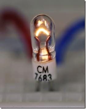
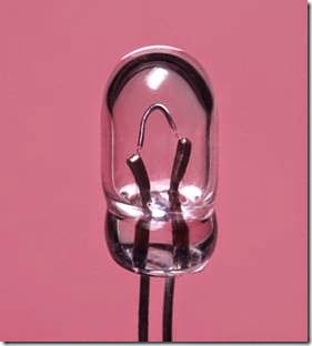
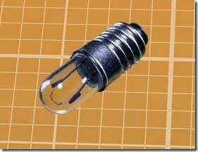
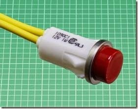
neon bulb:What It Does,How It Works,Construction,Ionization,Negative Resistance,How to Use It,Limited Light Output,Efficiency,Ruggedness,Failure in a Dark Environment,Premature Failure with DC,Premature Failure through Voltage Fluctuations and Replacement.

neon bulb

The terms neon bulb, neon indicator, and neon lamp tend to be used interchangeably. In this encyclopedia, a neon bulb is defined as a glass capsule containing two electrodes in neon gas (or a combination of gases in which neon is present). A neon lamp is an assembly containing a neon bulb, usually using a plastic tube with a tinted transparent cap at one end. A neon indicator is a miniature neon lamp that is usually panel-mounted.

Large-scale neon tubes used in signage are not included in this encyclopedia.

What It Does

When voltage is applied between two electrodes inside a neon bulb, the inert gas inside the bulb emits a soft red or orange glow. This color may be modified by using a tinted transparent plastic cap, known as a lens, in a neon lamp assembly.

A neon bulb is usually designed for a power sup- ply of 110V or higher. It functions equally well with alternating or direct current.

The schematic symbols in Figure 19-1 are commonly used to represent either a neon bulb or a neon lamp. They are all functionally identical. The black dot that appears inside two of the symbols indicates that the component is gas filled. The position of the dot inside the circle is arbitrary. Even though all neon bulbs are gas filled, the dot is often omitted.

Figure 19-1. Any of these symbols may represent a neon bulb or a neon lamp. The dot in two of the symbols indicates that the component is gas filled. All neon bulbs are gas filled, but the dot is often omitted.

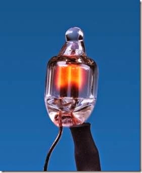
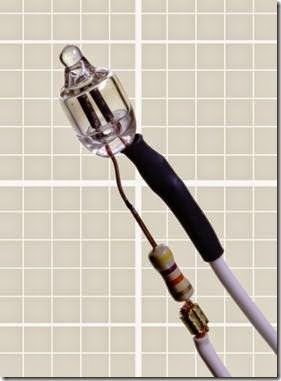
The photograph in Figure 19-2 shows a neon bulb with a series resistor preattached to one lead. Many bulbs are sold in this configuration, because a resistor must be used to limit current through the bulb. The bulb has no polarity and can be used on an AC or DC power supply. The same bulb is shown in its energized state in Figure 19-3.

clip_image007

Figure 19-2. A typical neon bulb with series resistor attached to one lead.

clip_image008How It Works
Construction

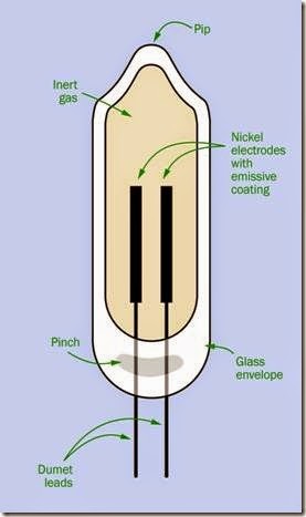
The parts of a neon bulb are illustrated in Figure 19-4. When the bulb is fabricated, it begins as a glass tube. The leads are made of dumet, consisting of a copper sheath around a nickel iron core. This has the same coefficient of expansion as glass, so that when the glass is heated and melted around the leads, it forms a seal that should be unaffected by subsequent temperature fluctuations. This area is known as the pinch in the tube.

Nickel electrodes are welded onto the leads be- fore the leads are inserted into the tube. The electrodes have an emissive coating that reduces the minimum operating voltage. The glass tube is filled with a combination of neon and argon gases, or pure neon for higher light output (which reduces the life of the component). The top end of the glass tube is heated until it melts, and is pinched off. This creates a distinctive protrusion known as the pip.

clip_image010

Figure 19-3. The same bulb from the previous photo- graph, energized with 115VAC.

Ionization

When a voltage is applied between the leads to the bulb, the gas becomes ionized, and electrons and ions are accelerated by the electric field. When they hit other atoms, these are ionized as well, maintaining the ionization level. Atoms are excited by collisions, moving their electrons to higher energy levels. When an electron returns from a higher level to a ground state, a photon is emitted.

This process begins at the starting voltage (also known as the striking voltage, the ignition volt- age, or the breakdown voltage) usually between 45V and 65V for standard types of bulb, or be- tween 70V and 95V for high-brightness types.

When the bulb is operating, it emits a soft radiance known as a glow discharge with a wave- length ranging from 600 to 700 nanometers.

clip_image012

Figure 19-4. The parts of a neon bulb. See text for details.

The ionization of the gas allows current to flow through it. This will continue even if the power supply is reduced by 10 to 20 volts to a level known as the maintaining voltage.

Negative Resistance

When the glow discharge persists below the starting voltage, this is a form of hysteresis, meaning that the neon bulb tends to “stick” in its on state. It remains on while its power supply de- creases to the maintaining voltage, but once it

switches off, it will “stick” in its off state until the power supply increases again above the maintaining voltage to the starting voltage. The concept of hysteresis is discussed in the entry on comparators. See Figure 6-2.

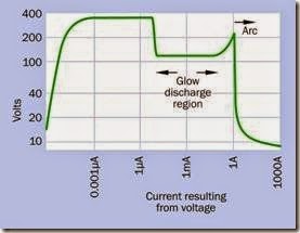
A neon bulb is said to have negative resistance. If the current is allowed to increase without restraint, the resistance eventually decreases while the current increases further. If this runaway behavior is not controlled, the bulb will destroy it- self.

This behavior is characteristic of gas-discharge tubes generally. A graph showing this appears in Figure 19-5. Note that both scales are logarithmic. Also note that the curve shows how current will be measured in response to voltage. If the voltage is reduced after it has increased, the transitional events shown by the graph will not recur in reverse order. This is especially true if arcing is allowed to begin, as it will almost certainly destroy the component.

clip_image014

Figure 19-5. A gas discharge tube, such as a neon bulb, is said to have a negative resistance, as current passing through it tends to increase uncontrollably after the gas is ionized and becomes conductive. (Derived from measurements made by David Knight, on a web page named after his radio ham call sign, G3YNH.)

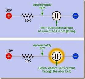
A neon bulb can be controlled very simply with a series resistor that maintains it in gas-discharge mode. To understand the operation of the resistor, consider the combination of the lamp and the resistor as a voltage divider, as shown in Figure 19-6. Before the lamp begins to pass cur- rent, it has an almost infinite resistance. There- fore, the voltage on both sides of the resistor will be approximately equal, the bulb passes almost no current, and it remains dark.

clip_image016

Figure 19-6. A series resistor is essential to limit the cur- rent through a neon bulb.

After the lamp begins to pass current, the requirement now is for the series resistor to reduce the voltage from the supply level (probably around 110V) to the maintaining level (probably around 90V). This means that the desired voltage drop is 20V, and if the manufacturer’s specification tells us that the lamp should pass 1mA (i.e.,

0.001 amps), R, the value of the series resistor, is given by Ohm’s Law:

R = 20 / 0.001

Thus, the value for R is 20K. In fact, the value of a resistor supplied with a neon bulb may range from 10K to 220K, depending on the characteristics of the bulb and the supply voltage that will be used.

Now if the bulb’s effective internal resistance falls radically, the resistor still limits the currrent. In a hypothetical worst-case scenario, if the bulb’s resistance drops all the way to zero, the resistor must now impose the full voltage drop of 110V, and the current, I, will be found by Ohm’s law:

I = 110 / 20,000 That is, about 5mA, or 0.005A.

Neon tubes used in signage require a more sophisticated voltage control circuit which is not included in this encyclopedia.

How to Use It

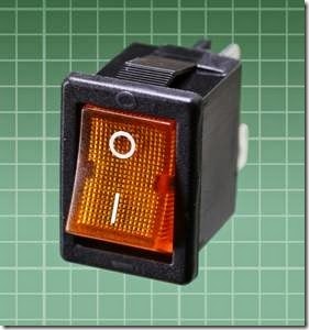
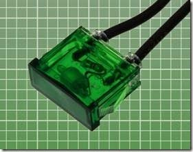
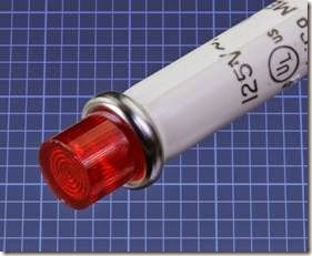
The use of a neon bulb for an indicator lamp is primarily limited to situations where domestic supply voltage (115VAC or 220VAC) is readily available. “Power on” lights are the obvious application, especially as neon indicators can accept AC. The switch shown in Figure 19-7 is illuminated by an internal neon bulb. The rectangular indicator in Figure 19-8 is designed to run on domestic supply voltage, and its internal bulb and resistor can be clearly seen through the green plastic. The assembly in Figure 19-9 is about 0.5” in diameter, which is the lower limit for neon indicators.

clip_image018

Figure 19-7. This power switch is illuminated by an internal neon bulb.

clip_image020

Figure 19-8. The neon bulb and its series resistor are visible inside this indicator.

clip_image022

Figure 19-9. A relatively small neon indicator lamp, de- signed for insertion in a hole 0.5” diameter.

Limited Light Output

Neon bulbs have a light output of around 0.06 lumens per milliamp of consumed power (standard brightness type) or 0.15 lumens per milliamp of consumed power (high brightness type).

Comparing this value with the intensity of LED indicators is difficult. Their light output is customarily measured in millicandelas (mcd), be- cause LED indicators almost always include a lens that focuses the light, and the candela is a measurement of luminous flux within an angle of dis-

persion. Moreover, because the intensity of neon indicators is not of great interest in most applications, datasheets usually do not supply an intensity value.

One way around the problem of comparisons is to use the standard of radiant luminous efficacy (LER), which is defined in the entry on incandescent lamps (see “Efficacy” on page 179). A standard-brightness neon bulb has an LER of about 50 lumens per emitted watt of luminous flux. A light-emitting diode may reach an LER of 100 lm/W. However, a neon bulb operates typi- cally around 1mA while an LED indicator may use 20mA. Therefore, a typical LED indicator may ap- pear to be 30 to 50 times brighter than a typical neon bulb.

Consequently, neon may be an inferior choice in a location where there is a high level of ambient light. Direct sunlight may render the glow of a neon indicator completely invisible.

Efficiency

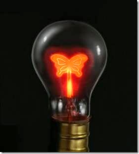
Because a neon bulb does not use a lot of power and generates negligible heat, it is a good choice where current consumption is a consideration (for example, if an indicator is likely to be on for long periods). The durability and low wattage of neon bulbs, and their convenient compatibility with domestic power-supply voltage, made them a favorite for night-lights and novelty lamps in the past. Figure 19-10 shows an antique bulb containing an ornamental electrode, while Figure 19-11 is a piece of folk art, approximately 1” in diameter, mounted on a plug-in plastic capsule containing a neon bulb.

Ruggedness

Neon bulbs are a good choice in difficult environments, as they are not affected by vibration, sudden mechanical shock, voltage transients, or frequent power cycling. Their operating temperature range is typically from -40 to +150 degrees Celsius, although temperatures above 100 degrees will reduce the life of the lamp.

clip_image024

Figure 19-10. In bygone decades, ornamental neon bulbs with specially shaped electrodes were popular.

clip_image026

Figure 19-11. Neon folk art survives in this hand-painted night-light sold in a Florida tourist shop.

Power-Supply Testing

When driven by DC current, only the negative electrode (the cathode) of a neon bulb will glow.

When AC current passes through the bulb, both terminals will glow.

If a bulb (with series resistor) is placed between the “hot” side of a domestic AC power supply and ground, the bulb will glow. If it is placed between the neutral side of the supply and ground, it will not glow.

These features enable a neon bulb to be used for simple power-supply testing.

Life Expectancy

The metal of the electrodes gradually vaporizes during everyday use of a neon bulb. This is known as sputtering and can be observed as the glass capsule becomes darkened by deposition of vaporized metal. The electrodes will have a more limited life in a lamp used with DC voltage, where sputtering affects only the cathode. Using AC, the electrodes take turns functioning as the cathode, and vaporization is distributed be- tween both of them.

Failure of a neon lamp can occur as sputtering erodes the electrodes to the point where the maintaining voltage will increase until it almost reaches the level of the power supply. At this point, the bulb will flicker erratically.

Failure can also be defined as a gradual reduction in brightness to 50% of rated light output, caused by accumulated deposition in the glass capsule. Because deposition occurs more heavily on the sides of the bulb, a longer apparent life is possible if the bulb is mounted so that it is viewed from the end.

Typically, neon bulbs are rated for 15,000 to 25,000 hours (two to three years of constant op- eration). However, the life can be greatly in- creased by a slight reduction in voltage, which may be achieved by substituting a series resistor with a slightly higher value.

The relationship between operating life and resistor value is shown below. If LA is the normal operating life, LB is the extended operating life,

RA is the normal resistor value, and RB is a higher resistor value:

LB = LA * ( RB / RA ) 3.3

For example, if a normal resistor value is 20K, and it is increased to 22K, the life of the lamp should increase by a factor of slightly more than 1.4.

Variants

A typical neon bulb terminates in leads, and a lamp assembly often has solder tabs, although it may have a base with a screw thread, flange, or bayonet pins for insertion into a compatible socket. A lamp assembly that does not use a base will either snap-fit into a hole of appropriate size and shape, or may be retained with a nut that engages with a plastic thread on the cylinder of the lamp.

Some neon bulbs or lamp assemblies terminate in pins for direct insertion into a printed circuit board.

Almost all neon bulbs operate either in the 100V to 120V range or in the 220V to 240V range.

Light intensity is expressed either as “standard” fied by their use of a numeral 5 that is a numeral 2 turned upside-down.

Nixie tubes typically require 170VDC. This creates a challenge for a power supply and switching, and can be a safety hazard.

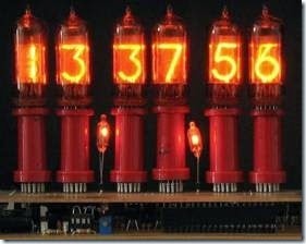
Figure 19-12 shows six Nixie-type tubes repurposed for use as a 24-hour digital clock.

clip_image028

Figure 19-12. A 24-hour clock using Nixie-type tubes. Source: Wikipedia, public domain.

What Can Go Wrong

or “extra-bright,” although datasheets usually do not define those terms.

Nixie Tubes

Nixie tubes, first marketed in 1955, were used to display numerals from 0 through 9 in the days before LEDs took over this capability. They are no longer being manufactured.

Each numeral was physically formed from metal and functioned as an electrode inside a tube filled with a neon-based gas mixture. The typo- graphical elegance of the digits and their aesthetically pleasing glow made Nixies enduringly popular. With a long lifespan, vintage tubes are still usable and can be purchased cheaply from sources such as eBay. Many originate in Russia, where Nixie-type displays were manufactured into the 1980s. The Russian tubes can be identiFalse Indication

Because a neon bulb requires so little power, it may be energized by induced voltages from else- where in a circuit, especially if inductive components such as transformers are used. To prevent this, a high-value resistor can be placed in parallel with the bulb, in addition to the series resistor that must always be used.

Failure in a Dark Environment Because a neon bulb requires a minimal amount of light to initiate its own photon emissions, it may take time to start glowing in a very dim environment, and may not light at all in total dark-ness. A few bulbs include a small amount of radioactive material that enables them to self-start in complete absence of ambient light.

Premature Failure with DC

The life expectancy quoted in datasheets for ne- on bulbs usually assumes that they are powered by AC. Because DC results in faster vaporization of the electrodes, the expected lifetime should be reduced by 50% if DC power will be used.

Premature Failure through Voltage Fluctuations

Because the deterioration of a neon bulb accelerates rapidly with current, a sustained voltage that passes slightly more current can radically reduce the expected lifespan.

Replacement

Replacement can be an issue with panel indicators, where disassembly of a device may be necessary to reach the bulb. Bear in mind, however, that an easily removable bulb becomes vulnerable to tampering.

 

incandescent lamp:What It Does,History,How It Works,Spectrum,Non-Incandescent Sources,Power Consumption,Variants,Miniature Lamps,Oven Lamps,Base Variants,Values,Power,Illuminance,Fire Risk,Current Inrush and Replacement Problems.

incandescent lamp

The terms incandescent light, incandescent bulb, and incandescent light bulb are often used interchangeably with incandescent lamp. Because the term “lamp” seems to be most common, it is used here. A panel-mounted indicator lamp is considered to be an assembly containing an incandescent lamp.

A carbon arc, which generates light as a self-sustaining spark between two carbon electrodes, can be thought of as a form of incandescent lamp, but is now rare and is not included in this encyclopedia.

What It Does

The term incandescent describes an object that emits visible light purely as a consequence of being hot. This principle is used in an incandescent lamp where a wire filament glows as a result of electric current passing through it and raising it to a high temperature. To prevent oxidation of the filament, it is contained within a sealed bulb or tube containing an inert gas under low pres- sure or (less often) a vacuum.

Because incandescent lamps are relatively inefficient, they are not considered a wise environ- mental choice for area lighting and have been prohibited for that purpose in some areas. How- ever, small, low-voltage, panel-mount versions are still widely available. For a summary of ad- vantages of miniature incandescent lamps relative to light-emitting diodes (LEDs) see “Relative Advantages” on page 179.

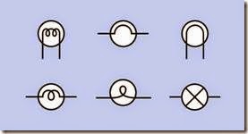
Schematic symbols representing an incandescent lamp are shown in Figure 18-1. The symbols are all functionally identical except that the one at bottom right is more likely to be used to rep- resent small panel-mounted indicators.

clip_image005

Figure 18-1. A variety of symbols can represent an incandescent lamp. The one at bottom right may be more commonly used for small panel-mounted indicators.

The parts of a generic incandescent light bulb are identified in Figure 18-2:

A: Glass bulb.

B: Inert gas at low pressure.

C: Tungsten filament.

D: Contact wires (connecting internally with brass base and center contact, below).

E: Wires to support the filament. F: Internal glass stem.

G: Brass base or cap. H: Vitreous insulation. I: Center contact.

clip_image007

Figure 18-2. The parts of a typical incandescent lamp (see text for details).

History

The concept of generating light by using electricity to heat a metal originated with English- man Humphrey Davy, who demonstrated it with a large battery and a strip of platinum in 1802. Platinum was thought to be suitable because it has a relatively high melting point. The lamp worked but was not practical, being insufficiently bright and having a short lifespan. In addition, the platinum was prohibitively expensive.

The first patent for an incandescent lamp was is- sued in England in 1841, but it still used platinum. Subsequently, British physicist and chemist Joseph Swan spent many years attempting to develop practical carbon filaments, and obtained a patent in 1880 for parchmentized thread. His house was the first in the world to be illuminated by light bulbs.

Thomas Edison began work to refine the electric lamp in 1878, and achieved a successful test with a carbonized filament in October 1879. The bulb lasted slightly more than 13 hours. Lawsuits over patent rights ensued. Carbonized filaments were used until a tungsten filament was patented in 1904 by the German/Hungarian inventor Just Sándor Frigyes and the Croatian inventor Franjo Hanaman. This type of bulb was filled with an inert gas, instead of using a vacuum.

Many other pioneers participated in the effort to develop electric light on a practical basis. Thus it is incorrect to state that “Thomas Edison invented the light bulb.” The device went through a very lengthy process of gradual refinement, and one of Edison’s most significant achievements was the development of a power distribution system that could run multiple lamps in parallel, using filaments that had a relatively high resistance. His error was insisting on using direct cur- rent (DC) while his rival Westinghouse pioneered alternating currrent (AC), enabling power trans- mission over longer distances through the use of transformers. The use of AC also enabled Tesla’s brushless induction motor.

By the mid-1900s, most incandescent bulbs used tungsten filaments.

How It Works

All objects emit electromagnetic radiation as a function of their temperature. This is known as black body radiation, based on the concept of an object that absorbs all incoming light, and thus does not reflect any sources from outside itself. As its temperature increases, the intensity of the radiation increases while the wavelength of the radiation tends to decrease.

If the temperature is high enough, the wave- length of the radiation enters the visible spec- trum, between 380 and 740 nanometers. (A nanometer is one-billionth of a meter.)

The melting point of tungsten is 3,442 degrees Celsius, but a lamp filament typically operates between 2,000 and 3,000 degrees. At the higher end of this scale, evaporation of metal from the filament tends to cause deposition of a dark residue on the inside of the bulb, and erodes the filament more rapidly, to the point where it eventually breaks. At the lower end of this scale, the light will be yellow and the intensity will be reduced.

Spectrum

The color of black-body radiation is measured using the Kelvin temperature scale. The increment of 1 degree Kelvin is the same as 1 degree Celsius, but the Kelvin scale has a zero value at absolute zero. This is the theoretical lowest conceivable temperature, at which there is complete absence of heat. It is approximately –273 degrees Celsius.

From this it is evident that if K is a temperature in degrees Kelvin and C is a temperature in degrees Celsius:

K = C + 273 (approximately)

Calibration of light sources in degrees Kelvin is common in photography. Many digital cameras allow the user to specify the color temperature of lights that are illuminating an indoor scene, and the camera will compensate so that the light source appears to be pure white with all colors in the visible spectrum being represented equally.

Some computer monitors also allow the user to specify a white value in degrees Kelvin.

Color temperature is used in astronomy, because the spectrum of many stars is comparable with that of a theoretical black body.

A color temperature of 1,000 degrees K will have a dark orange hue, while 15,000 degrees K or higher will have a blue hue comparable to that of a pale blue sky. The color temperature of the sun is approximately 5,800 K. Interior lighting is often around 3,000 K, which many people find acceptable because it creates pleasant flesh tones. An incandescent bulb described by the manufacturer as “soft white” or “warm” will have a lower color temperature than one which is sold as “pure white” or “paper white.”

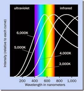
Graphs showing the emission of wavelengths at various color temperatures are shown in Figure 18-3. The rainbow section indicates the approximate range of visible wavelengths be- tween ultraviolet, on the left, and infrared, on the right. For purposes of clarity, the peak intensity for each color temperature has been equalized. In reality, increasing the temperature also increases the light output.

clip_image011

Figure 18-3. Approximate peak wavelengths for black- body radiation at various color temperatures in degrees Kelvin. The curves have been adjusted so that their peak values are equalized. Adapted from an illustration in the reference book Light Emitting Diodes by E. Fred Schubert.

Non-Incandescent Sources

So long as light is generated by heating a filament, plotting the intensity against wavelength will result in a smooth curve without irregularities. A higher Kelvin value will simply displace and compress the curve laterally without changing its basic shape to a significant degree.

The introduction of fluorescent sources and, subsequently, light-emitting diodes (LEDs) has complicated this scenario. Because they are luminescent rather than incandescent, they do not generate an evenly weighted, continuous range of wavelengths.

LEDs tend to emit monochromatic light, meaning that it is tightly centered around just one col- or. A “white” LED is really a blue LED in which a phosphor coating on the semiconductor die is excited to create light over a broader range. A fluorescent light tends to create spectral lines which show up as sharp peaks at a few wave- lengths determined by the mercury inside the bulb. Figure 18-4 illustrates these problems.

The human eye tends to compensate for the yellow emphasis of incandescent lamps and for the irregularities in spectra emitted by other light sources. Also, the eye is often unable to distinguish between “white” light created as a mix of all the visible wavelengths, and light that appears white even though it is dominated by a few isolated wavelengths from a fluorescent source.

However, when the eye views colors that are illuminated by a source that has gaps in its spectrum, some of the colors will appear unnaturally dull or dark. This is true also if an imperfect source is used as a backlight to create colors on a video monitor. Colors rendered by different light sources are shown in Figure 23-7 and subsequent figures.

clip_image013

Figure 18-4. The relative performance of three light sources compared with sensitivity of the human eye to the visible spectrum. Note that the range of wavelengths on the horizontal scale in this figure is not the same as the range in the previous figure. The color assigned to each curve is arbitrary. Adapted from VU1 Corporation.

Photography is adversely affected by the use of LEDs or fluorescents as a light source. Reds, for example, can seem dark when lit by white LEDs, while blues can be inappropriately intense. Be- cause the source does not have an emission curve comparable to that of an incandescent light, the auto-white balance feature of a digital camera may be unable to address this problem, and it cannot be resolved by entering a different Kelvin number manually.

The fidelity with which a light source is capable of displaying the full visible spectrum is known as the color rendering index (CRI), ranging from a perfect score of 100 down to 0 or even lower (sodium-vapor street lighting has a negative val- ue). Computing the index requires standard reference color samples and has been criticized for generating scores that do not correlate well with subjective assessments.

Incandescent bulbs can have a CRI of 100, while an uncorrected “white” LED may score as low as 80.

Power Consumption

Approximately 95% of the power consumed by an incandescent lamp generates heat instead of visible light. This wastage of power in room lighting is compounded by the power consumption of air conditioning to remove the heat from en- closed spaces in hot climates. While the heat from incandescent lamps does reduce the need for space heating in cold environments, heat is delivered more efficiently by using systems de- signed for that purpose. Consequently, greater energy efficiency can be achieved with a light source that generates less heat, regardless of ambient air temperature.

Variants
Miniature Lamps

Prior to the development of LEDs, all light- emitting panel-mounted indicators were either neon bulbs or incandescent lamps. The use of neon is limited by its need for a relatively high voltage.

Miniature incandescents were the traditional choice for battery-powered light sources, and at the time of writing are still used in cheap flash- lights. Variants are available that are as small as a 5mm LED, with a claimed life expectancy that is comparable, although they draw more current to generate an equivalent light intensity, because much of their power is wasted in infrared wave- lengths.

The photograph in Figure 18-5 is of a miniature lamp terminating in pins spaced 0.05” apart. The total height of the lamp, including its ceramic base, is less than 0.4,” while its diameter is just over 0.1”. It draws 60mA at 5V and is rated for 25,000 hours.

The photograph in Figure 18-6 is of a lamp of similar size and power consumption, but terminating in wire leads and rated for 100,000 hours. It emits 0.63 lumens.

clip_image015

Figure 18-5. A miniature lamp less than 0.4” high, terminating in pins spaced 0.05” apart.

clip_image017Figure 18-6. This lamp is 0.25” high and terminates in wire leads.

The lamp pictured in Figure 18-7 is slightly larger, with a glass envelope about 0.25” diameter. It is rated for less than half the lifetime of the lamp in Figure 18-6 but emits three times as much light

—a typical tradeoff. Various base styles are avail- able.

clip_image019

Figure 18-7. This lamp has a glass envelope about 0.35” high. Its screw-in base makes it easier to replace than an LED.

In the United States, the light output from miniature incandescent lamps may be measured in lumens, but is more often rated in mean spherical candlepower (MSCP). An explanation of light measurement is included in “MSCP” on page 178.

Lamp lenses provide a quick and simple way to add color to a miniature incandescent lamp. Usually the lens is cylindrical with a hemispherical end cap, and is designed to push-fit or snap-fit over a small lamp. Even when the cap is translucent, it may still be referred to as a lens.

Panel-Mount Indicator Lamps

This term often refers to a tubular assembly containing a miniature lamp, ready for installation.

The enclosure is often designed to snap-fit into a hole drilled in the panel. If the incandescent bulb inside the enclosure cannot be replaced, the component is said to be “non-relampable.” Figure 18-8 shows a 12-volt panel-mount indicator lamp.

clip_image021

Figure 18-8. This panel-mount indicator lamp is designed to push-fit into a hole 1/2” in diameter. The bulb inside it is not replacable, causing the assembly to be classified as “non-relampable.”

Halogen or Quartz-Halogen

This is a type of incandescent lamp containing gases under pressure in which halogens such as iodine or bromine cause evaporated tungsten atoms to be redeposited on the filament. A halogen lamp can therefore operate at a higher temperature, creating a light that is less yellow and brighter than that from a comparable incandescent lamp. It also enables a smaller bulb, but requires an envelope of borosilicate-halide glass (often termed fused quartz) instead of regular glass. A halogen lamp will be slightly more efficient than an incandescent bulb of the same wattage, and will last longer.

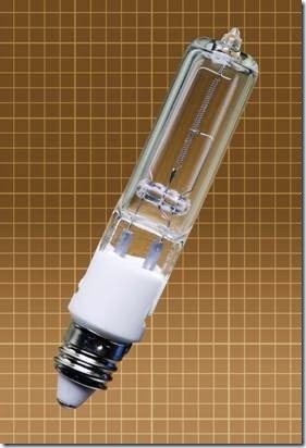
Halogens are available in a variety of formats. The small bulb pictured in Figure 18-9 consumes 75W, emitting 1,500 lumens at 3,000 degrees Kelvin. The light intensity is claimed to be equivalent to that of a 100W incandescent bulb. It has a mini-candelabra base.

Oven Lamps

Oven lamps are designed to withstand the high temperature in an oven. Typically they are usable with ambient temperatures up to 300 degrees C. A common power rating is 15W.

clip_image023

Figure 18-9. A halogen bulb slightly more than 2” in length, designed for 115VAC.

Base Variants

Miniature lamps are available with a wide variety of connection options, including wire terminals, single-contact bayonet, double-contact bayonet, miniature screw base, and fuse style. Most of these options require a matching socket.

Screw-in lamps for room illumination are common in household lighting in the United States and many other countries (but not in the UK, where bayonet fittings are used). The US socket size is designated by letter E followed by a number that gives the socket diameter in millimeters. Common sizes are E10, E14 and E27.

A bayonet base is fitted with two small lugs protruding on opposite sides. The lamp is secured by pushing it in and twisting it to engage the lugs in slots in the socket. The advantage of a bayonet

base is that the bulb is less likely to become loose as a result of vibration.

A pin base consists simply of a pair of pins that will push-fit into small holes in a socket.

A flange base has a flange that engages in a sock- et where flexible segments will retain it.

A wedge base is forced between two contacts which retain the bulb by friction.

Some indicator lamps terminate simply in long, thin leads that can be soldered.

Values

While the power consumption of full-size incandescent lamps is rated in watts, small indicator lamps are rated in milliamps at the voltage for which they are designed. Miniature lamps may require specific voltages ranging from as low as 2V to 24V. A higher voltage generally necessitates a longer filament, which may entail a larger bulb.

The light that a lamp will emit can be measured in two ways: either as the power of the lamp (not its power consumption, but its radiating power), or as the light delivered to a specific area at a specific distance. These two measurements may differ because a lamp may concentrate its light in a beam, as in the case of a reflector bulb or an LED.

Power

Flux, in watts, is a measurement of energy flow in joules per second. The total radiating power of a lamp, in all wavelengths, in all directions, is known as its radiant flux. Because invisible wave- lengths are of little interest when assessing the brightness of a lamp, the term luminous flux is used to describe the apparent brightness of the lamp in the visible spectrum. The unit for luminous flux is the lumen.

The human eye is most responsive to yellow- green hues in the center of the spectrum. Consequently, the measurement of luminous flux is weighted toward green at a wavelength of 555 nanometers. Red and violet are considered to have low luminous flux, while infrared and ultra- violet have a zero value.

When considering a value expressed in lumens, remember:

• Lumens are a measure of the total radiated power output of a light source, in all directions, in the visible spectrum only, weighted toward the characteristics of the human eye.

• The number of lumens of a light source does not define the direction in which the light is shining, or its uniformity.

• The abbreviation for lumen is lm.

A conventional incandescent lamp that consumes 100W of electricity is likely to have a light output of about 1,500 lumens. A 40W fluorescent tube can have a light output of about 2,600 lumens.

Illuminance

The illuminance of a light source is defined as the luminous flux per unit of area. This can be thought of as the brightness of a surface illuminated by the source.

Illuminance is measured in lux, where 1 lux = 1 lumen per square meter. For accurate calibration, the illuminated surface should be spherical in shape, and must be located 1 meter from the light source, with the source at the geometrical center of the sphere.

Illuminance used to be measured in foot- candles, where 1 foot-candle was 1 lumen per square foot.

• The number of lumens per square meter (lux) does not define the size of the illuminated area, only the brightness per unit of area.

• A lamp that has a tightly focused beam can achieve a high lux rating. When selecting a lamp for an application, the angle of dispersion of the beam must be considered in con- junction with its lux rating.
Intensity

A candela measures the luminous flux within an angle of dispersion. The angle is three- dimensional, and can be imagined as the sharp- ness of a point of a cone, where the light source is at the point and the cone represents the dispersion of light.

The three-dimensional angle of dispersion is measured in steradians. If a light source is at the center of a sphere that has a radius of 1 meter, and is illuminating one square meter of the surface of the sphere, the angle of dispersion is 1 steradian.

• A source of 1 lumen which projects all its light through a dispersion angle of 1 steradian is rated at 1 candela.

• The number of candelas does not define the angle of dispersion, only the intensity within that angle.

• A light source rated for 1,000 candelas could have a power of 10 lumens concentrated within an angle of 0.01 steradians, or could have a power of only 1 lumen concentrated within an angle of 0.001 steradians.

• There are 1,000 millicandelas in 1 candela. The abbreviation for candela is cd while the abbreviation for a millicandela is mcd.

• LEDs are often rated in mcd. The number de- scribes the intensity of light within its angle of dispersion.

MSCP

Although the term candlepower is obsolete, it has been redefined as being equal to 1 candela. Mean spherical candlepower (MSCP) is a measurement of all the light emitted from a lamp in all directions. Because the light is assumed to be omnidirectional, it fills 4 * π (about 12.57) steradians. Therefore 1 MSCP = approximately 12.57

lumens. In the United States, MSCP is still the most common method of rating the total light output of a miniature lamp.

Efficacy

The radiant luminous efficacy (abbreviated LER) assesses how effective a lamp is at channeling its output within the visible spectrum, instead of wasting it in other wavelengths, especially infra- red. LER is calculated by dividing the power emit- ted in the visible spectrum (the luminous flux) by the power emitted over all wavelengths.

Thus, if VP is the power emitted in the visible spectrum, and AP is the power emitted in all wavelengths:

LER = VP / AP

LER is expressed in lumens per watt. It can range from a low value of around 12 lm/W for a 40W incandescent bulb to 24 lm/W for a quartz halo- gen lamp. Fluorescent lamps may average 50 lm/ W. LEDs vary, but can achieve 100 lm/W.

Efficiency

The radiant luminous efficiency (abbreviated LFR) of a lamp measures how good its radiant luminous efficacy is, compared with an imaginary ideal lamp. (Note the difference between the words “efficiency” and “efficacy.”) LFR is deter- mined by dividing the radiant luminous efficacy (LER) by the maximum theoretical LER value of 683 lm/W, and multiplying by 100 to express the result as a percentage. Thus:

LFR = 100 * ( LER / 683 )

The LFR ranges from around 2% for a 40W bulb to 3.5% for a quartz halogen lamp. LEDs may be around 15% while fluorescents are closer to 10%.

How to Use It

When first introduced, LEDs were limited by their higher price, lower maximum light output, and inability to display blue or white. The price difference has disappeared for small indicators, while gaps in the color range have been filled

(although the color rendering index of LEDs is still inferior).

Brightness remains an advantage for large incandescents relative to LEDs, as they are more upwardly scalable. However, fluorescents and vapor lamps have an advantage for very high light output, as in the lighting of big-box stores or parking lots. Thus the range of applications for incandescent bulbs is diminishing, especially be- cause common types are now illegal for domes- tic light fixtures in many parts of the world.

Relative Advantages

When choosing whether to use an incandescent lamp or an LED, these advantages of an incandescent lamp should be considered:

• The intensity can be adjusted with a triacbased dimmer. Regular fluorescents cannot be dimmed, while LEDs often require different dimmer circuitry.

• The intensity can also be adjusted with a rheostat. The output from fluorescents can- not.

• Easy white-balance correction. LEDs and fluorescents do not naturally produce a consistent output over the visible spectrum.

• Can be designed to operate directly from a wide range of voltages (down to around 2V and up to around 300V). A higher voltage entails a longer filament wire, which may re- quire a larger bulb. LEDs require additional components and circuitry to use higher voltages.

• Incandescent bulbs are more tolerant of volt- age fluctuations than LEDs. With battery operation, the incandescent will still provide some reduced light output when the voltage has diminished radically. LEDs will not per- form at all at currents lower than their threshold.

• An incandescent is nonpolarized and may be socketed, which simplifies user replacement.

LEDs are polarized and are usually soldered in.

• Can be powered by AC or DC without any modification or additional circuitry. LEDs re- quire DC, which must be provided through a transformer and rectifier, or similar electronics, if AC power is the primary source.

• Can be equally visible from a wide range of viewing angles. LEDs have restricted viewing angles.

• The heat output from an incandescent bulb may occasionally be useful (for example in a terrarium, or in incubators for poultry).

• Trouble-free switching. Fluorescents tend to hesitate and blink when power is applied, and they require a ballast to energize them. The lifespan of fluorescents is reduced by frequent switching.
• No low-temperature problems. Incandescent lamps are not significantly affected by low temperatures. Fluorescents may not start easily in a cold environment, and may flicker or glow dimly for 10 minutes (or more) until they are warm enough to function properly.

• Easy disposal. Fluorescent lights contain small quantities of mercury that are an environmental hazard. They should not be mixed with ordinary trash. Compact fluorescent

although the lifetime of a small panel indicator can be equal to that of an LED if a low color temperature is acceptable.

• Requires a filter or tinted glass envelope to generate colored light. This further reduces the lamp’s efficiency.

• Cannot be miniaturized to the same degree as an LED indicator.

Derating

The lifespan of a lamp can be greatly extended by choosing one with a higher current rating or using it at a lower voltage. The light output will be reduced, and the color temperature will be at a lower Kelvin number, but in some situations this tradeoff may be acceptable.

The graphs in Figure 18-10 suggest that if the voltage of a hypothetical miniature lamp is reduced to 80% of the manufacturer’s recommended value, this can make the lamp last 20 times as long. Note, however, that this will cut the light intensity to 50% of its normal value.

Conversely, using 130% normal voltage will give 250% of the normal light output, while shortening the life of the lamp to 1/20 of its normal value. Naturally these figures are approximations that may not apply precisely to a specific lamp.

What Can Go Wrong

lamps (CFLs) and LEDs used for room lighting will be packaged with electronics that should ideally be recycled, although this is not very practical. Incandescent bulbs impose the least burden on the environment when they are thrown away.

However, the incandescent lamp has some obvious disadvantages:

• Relatively inefficient.

• More susceptible to vibration.

• More fragile.

• Likely to have a shorter natural life expectancy than LEDs, fluorescents, or neon bulbs,

High Temperature Environment

If an incandescent lamp is used in an environment hotter than 100 degrees Celsius, the life of the lamp is likely to be reduced by the “water cycle.” Any water molecules inside the glass envelope will break down, allowing oxygen to com- bine with the tungsten filament to form tungsten oxide. The tungsten is deposited on the inside of the glass while the oxygen is liberated and be- gins a new cycle.

clip_image026

Figure 18-10. The life expectancy of a hypothetical miniature lamp is very strongly influenced by voltage. Applying only 60% of the rated voltage can make a lamp last 500 times its normal lifespan, although it will greatly reduce light output. Note that the vertical axes apply to curves of the same color. Adapted from “Characteristics of Miniature Lamps” from Toshiba Lighting and Technology Corporation.

Fire Risk

The partially evacuated bulb of an incandescent lamp provides some separation and protection from the heat in the filament, but if the bulb can- not disperse heat by radiation or convection, its temperature can rise to the point where it ignites flammable materials.

Halogen lamps have an elevated fire risk because they operate at a higher temperature and are smaller, providing less surface area to disperse the heat. They also contain gases under seven to eight atmospheres of pressure. Thermal stress can cause a halogen bulb to shatter, and finger- prints on the glass can increase this risk.

Current Inrush

When an incandescent lamp is first switched on, its filament has one-tenth the resistance that it will exhibit when it becomes hot. Consequently, the lamp will take a large initial surge of current, which stabilizes after about 50 milliseconds. This should be considered if one or more small lamps shares a DC power supply with components such as logic chips that may be sensitive to voltage fluctuations.

Replacement Problems

Because of the limited life of incandescent lamps, they should be installed in such a way that they are easy to replace. This can be an issue with panel indicators, where disassembly of a device may be necessary to reach the lamp.

The range of small incandescent lamps is diminishing, and may continue to diminish in the future. Future availability of replacement lamps should be considered when designing a circuit. When building equipment in small quantities, spare lamps should be purchased for future use.


LCD:What It Does,How It Works,Variants,Active and Passive Types,Crystal Types,Seven-Segment Displays,Additional Segments,Dot-Matrix Displays,Color,Backlighting Options,Zero-Power Displays,How to Use It,Numeric Display Modules and Alphanumeric Display Module.

LCD

The full term liquid-crystal display is seldom used. Its acronym, LCD, is much more common. Sometimes the redundant combination LCD display is found. All three terms refer to the same device. In this encyclopedia, the first two words in liquid-crystal display are hyphenated because they are an adjectival phrase. Other sources often omit the hyphen.

The acronym LED (for light-emitting diode) is easily confused with LCD. While both devices display information, their mode of action is completely different.

What It Does

An LCD presents information on a small display panel or screen by using one or more segments that change their appearance in response to an AC voltage. The display may contain alphanumeric characters and/or symbols, icons, dots, or pixels in a bitmap.

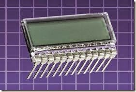
Because of its very low power consumption, a basic monochrome LCD is often used to display numerals in battery-powered devices such as digital watches and calculators. A small liquid- crystal display of this type is shown in Figure 17-1.

Color-enabled, backlit LCDs are now frequently used in almost all forms of video displays, including those in cellular telephones, computer monitors, game-playing devices, TV screens, and air- craft cockpit displays.

How It Works

Light consists of electromagnetic waves that possess an electric field and a magnetic field. The fields are perpendicular to each other and to the direction in which the light is traveling, but the field polarities are randomly mixed in most visible radiation. This type of light is referred to as incoherent.

clip_image006

Figure 17-1. A small, basic monochrome LCD.

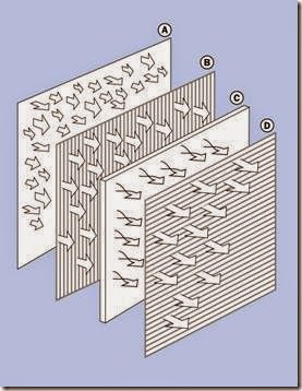
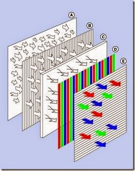
Figure 17-2 shows a simplified view of an LCD that uses a backlight. Incoherent light emerges from the backlight panel (A) and enters a vertical polarizing filter (B) that limits the electric field vector. The polarized light then enters a liquid crystal (C) which is a liquid composed of molecules organized in a regular helical structure that rotates the polarity by 90 degrees when no volt- age is applied to it. The light now passes through

a horizontal polarizing filter (D) and is visible to the user.

clip_image008

Figure 17-2. The combination of two polarizers and a liquid crystal appears transparent when voltage is not applied. See text for details.

• A liquid crystal itself does not emit light. It can only modify light that passes through it.

Figure 17-3 shows what happens when voltage is applied to the liquid crystal via transparent electrodes (not included in the figure). The molecules reorganize themselves in response to the electric potential and allow light to pass without changing its polarity. Consequently, the vertically polarized light is now blocked by the front, horizontally polarized filter, and the display be- comes dark.

A liquid crystal contains ionic compounds that will be attracted to the electrodes if a DC voltage is applied for a significant period of time. This can degrade the display permanently. Therefore, AC voltage must be used. An AC frequency of 50Hz to 100Hz is common.

clip_image010

Figure 17-3. The LCD appears dark when voltage is applied. See text for details.

Variants

A transmissive LCD requires a backlight to be visible, and is the type illustrated in Figure 17-2. In its simplest form, it is a monochrome device, but is often enhanced to display full color by adding red, green, and blue filters. Alternatively, instead of a white backlight, an array of pixel-sized red, green, and blue LEDs may be used, in which case filters are unnecessary.

Backlit color LCDs have displaced cathode-ray tubes, which used to be the default system in al- most all video monitors and TVs. LCDs are not only cheaper but can be fabricated in larger sizes. They do not suffer from burn in, where a persistent unchanging image creates a permanent scar in the phosphors on the inside of a tube. How- ever, large LCDs may suffer from dead pixels or stuck pixels as manufacturing defects. Different manufacturers and vendors have varying policies regarding the maximum acceptable number of pixel defects.

In a reflective LCD, the structure is basically the same as that shown in Figure 17-2 except that a reflective surface is substituted for the backlight. Ambient light enters from the front of the display, and is either blocked by the liquid crystal in combination with the polarizing filters, or is allowed to reach the reflective surface at the rear, from which it reflects back through the liquid crystal to the eye of the user. This type of display is very easily readable in a bright environment, but will be difficult to see in dim conditions and will be invisible in darkness. Therefore, it may be augmented with a user-activated light source mounted at the side of the display.

A transreflective LCD contains a translucent rear polarizer that will reflect some ambient light, and is also transparent to enable a backlight. While this type of LCD is not as bright as a reflective LCD and has less contrast, it is more versatile and can be more energy efficient, as the backlight can be switched off automatically when ambient light is bright enough to make the display visible.

Active and Passive Types

An active matrix LCD adds a matrix of thin-film transistors to the basic liquid-crystal array, to store the state of each segment or pixel actively while the energizing AC voltage transitions from positive to negative. This enables a brighter, sharper display as crosstalk between adjacent pixels is reduced. Because thin-film transistors are used, this is often described as a TFT display; but the term is interchangable with active matrix.

A passive matrix LCD is cheaper to fabricate but responds sluggishly in large displays and is not so well suited to fine gradations in intensity. This type of component is used primarily in simple monochrome displays lacking intermediate shades of gray.

Crystal Types

Twisted Nematic (TN) are the cheapest, simplest type of LCD, allowing only a small viewing angle and average contrast. The appearance is limited to black on gray. The response rate is relatively slow.

Super Twisted Nematic (STN) displays were developed in the 1980s for passive LCDs, enabling better detail, wider view angle, and a faster response. The natural appearance is dark violet or black on green, or dark blue on silver-gray.

Film-compensated Super Twisted Nematic (FSTN) uses an extra coating of film that enables a pure black on white display.

Double Super Twisted Nematic provides further enhancement of contrast and response times, and automatic contrast compensation in response to ambient temperature. The appearance is black on white. This display requires backlighting.

Color Super Twisted Nematic (CSTN) is an STN dis- play with filters added for full color reproduction.

Seven-Segment Displays

The earliest monochrome LCDs in devices such as watches and calculators used seven segments to display each numeral from 0 through 9. This type of LCD is still used in low-cost applications. A separate control line, or electrode, connects to each segment, while a backplane is shared by all the segments, connecting with a common pin to complete the circuit.

Figure 17-4 shows a typical seven-segment dis- play. The lowercase letters a through g that identify each segment are universally used in data- sheets. The decimal point, customarily referred to as “dp,” may be omitted from some displays. The array of segments is slanted forward to en- able more acceptable representation of the diagonal stroke in numeral 7.

clip_image012

Figure 17-4. Basic numeric display format for LCD numeric displays (the same layout is used with LEDs). To identify each segment, lowercase letters are universally used.

Seven-segment displays are not elegant but are functional and are reasonably easy to read, as shown in Figure 17-5. Letters A, B, C, D, E, and F (displayed as A, b, c, d, E, F because of the restrictions imposed by the small number of segments) may be added to enable display of hexadecimal values.

In appliances such as microwave ovens, very basic text messages can be displayed to the user within the limitations of 7-segment displays, as suggested in Figure 17-6.

The advantage of this system is low cost, as 7- segment displays are cheap to fabricate, entail the fewest connections, and require minimal de- coding to create each alphanumeric character. However, numbers 0, 1, and 5 cannot be distinguished from letters O, I, and S, while letters containing diagonal strokes, such as K, M, N, W, X, and Z, cannot be displayed at all.

clip_image014

Figure 17-5. Numerals and the first six letters of the alphabet created with a 7-segment display.

Additional Segments

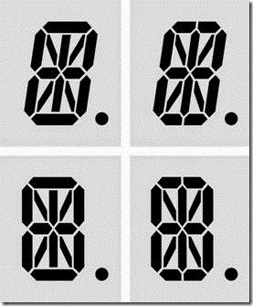
Alphanumeric LCDs were developed using 14 or 16 segments to enable better representation of letters of the alphabet. Sometimes these displays were slanted forward, like the 7-segment dis- plays, perhaps because the style had become familiar, even though the addition of diagonal segments made it unnecessary. In other cases, the 14 or 16 segments were arrayed in a rectangle. See Figure 17-7.

The same words represented in Figure 17-6 are shown in Figure 17-8, using 16-segment LCDs. Clearly, the advantage gained by enabling diagonal strokes entailed the disadvantage of larger gaps in the letters, making made them ugly and difficult to read.


clip_image018Figure 17-6. Basic text messages can be generated with 7-segment displays, although they cannot contain alphabetical letters that use diagonal strokes.

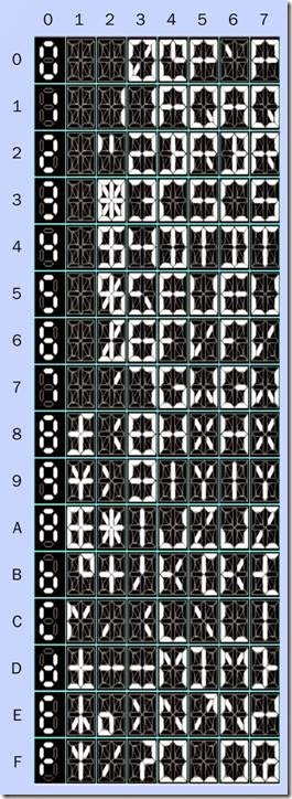
A full character set using 16-segment LCDs is shown in Figure 17-9. This conforms partially with the ASCII coding system, in which each character has an identifying numeric code ranging from 20 hexadecimal for a letter-space to 7A hexadecimal for letter z (although this character set does not attempt to represent lowercase letters differently from uppercase). The ASCII acronym stands for American Standard Code for Information Interchange.

Because backlit LCDs had become common by the time 16-segment displays were introduced, the characters were often displayed in light-on- dark or “negative” format, as suggested in this figure. LEDs, of course, have always used the light-on-dark format, as an LED is a light-emitting component.

clip_image016

Figure 17-7. LCDs using 14 segments (left) and 16 segments (right) were introduced to represent a full alphabet in addition to numerals. Sometimes these displays were slanted forward, like the previous 7-segment type, even though this was no longer necessary to represent the number 7.

Dot-Matrix Displays

The 16-segment displays were never widely popular, and the declining cost of microprocessors, LCD fabrication, and ROM storage made it economic to produce displays using the more easily legible 5×7 dot-matrix alphabet that had been common among early microcomputers. Figure 17-10 shows a dot-matrix character set that is typical of many LCDs.

Because the original ASCII codes were not standardized below 20 hexadecimal or above 7A hexadecimal, manufacturers have represented a variety of foreign-language characters, Greek letters, Japanese characters, accented letters, or symbols using codes 00 through 1F and 7B through FF. The lower codes are often left blank, allowing user installation of custom symbols. Codes 00 through 0F are often reserved for control functions, such as a command to start a new

line of text. There is no standardization in this area, and the user must examine a datasheet for guidance.

clip_image022

Figure 17-8. The same text messages shown previously using 7-segment LCDs are shown here using 16-segment displays.

Dot-matrix LCDs are usually packaged in arrays consisting of eight or more columns and two or more rows of characters. The number of columns is always stated before the number of rows, so that a typical 8 x 2 display contains eight alpha- numeric characters in two horizontal rows. An array of characters is properly referred to as a display module, but may be described, confus- ingly, as a display, even though a single seven- segment LCD is itself a display. A 16×2 display module is shown from the front in Figure 17-11

and from the rear in Figure 17-12.

clip_image020

Figure 17-9. A full character set using 16-segment LCDs.

clip_image024

Figure 17-10. A dot-matrix character set typical of LCDs capable of displaying a matrix of 5×7 dots.

clip_image026

Figure 17-11. A 16×2 LCD display module seen from the front.

clip_image028

Figure 17-12. The same 16×2 LCD display module from the previous figure, seen from the rear.

Multiple-character display modules have been widely used in consumer electronics products such as audio components and automobiles where simple status messages and prompts are necessary—for example, to show the volume setting or broadcast frequency on a stereo receiver. Backlighting is almost always used.

Because the cost of small, full-color, high- resolution LCD screens has been driven down rapidly by the mass production of cellular phones, color displays are likely to displace monochrome dot-matrix LCD display modules in many applications. Similarly, touchscreens will tend to displace pushbuttons and tactile switches. Touchscreens are outside the scope of this encyclopedia.

Color

The addition of filters to create a full color display is shown in simplified form in Figure 17-13.

clip_image030

Figure 17-13. The addition of red, green, and blue color filters, in conjunction with variable density liquid crystal pixels, enables an LCD full-color display.

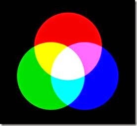
Red, green, and blue are almost always used as primary colors for transmitted light, because the combination of different intensities of these RGB primaries can create the appearance of many colors throughout the visible spectrum. They are said to be additive primaries, as they create brighter colors when they are combined. The principle is illustrated in Figure 17-14.

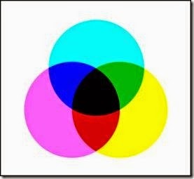
The use of the word “primaries” to refer to red, green, and blue can cause confusion, as full-color printed materials use a different set of reflective primaries, typically cyan, magenta, and yellow, often with the addition of black. In this CMYK system, additional layers of pigment will absorb, or subtract, more visible frequences. See Figure 17-15.

clip_image032

Figure 17-14. When colors red, green, and blue are trans- mitted directly to the eye, pairs of these additive primaries create secondary colors cyan, magenta, and yellow. Combining all three additive primaries creates an approximation of white light. This can be verified by viewing a color monitor with a magnifying glass.

clip_image034

Figure 17-15. When ink colors cyan, magenta, and yellow are superimposed on white paper and are viewed in white light, pairs of these subtractive primaries create secondary colors red, green, and blue. Overprinting all three subtractive primaries creates an approximation of black, limited by the reflective properties of available pigments. Black ink is usually added to provide additional contrast.

The complete range of colors that can be created as a combination of primaries is known as the gamut. Many different RGB color standards have been developed, the two most widely used being sRGB (almost universal in web applications) and Adobe 1998 (introduced by Adobe Systems for Photoshop, providing a wider gamut). None of the available systems for color reproduction comes close to creating the full gamut that can be perceived by the human eye.

Backlighting Options

For monochrome LCDs, electroluminescent backlighting may be used. It requires very low current, generates very little heat, and has a uniform output. However, its brightness is severely limited, and it requires an inverter that adds significantly to the current consumption.

For full-color LCDs, fluorescent lights were originally used. They have a long lifetime, generate little heat, and have low power consumption. However, they require a relatively high voltage, and do not work well at low temperatures. Early flat screens for laptop computers and desktop monitors used cold-cathode fluorescent panels.

Subsequently, white light-emitting diodes (LEDs) were refined to the point where they generated a range of frequencies that was considered acceptable. Light from the LEDs passes through a diffuser to provide reasonably consistent illumination across the entire screen. LEDs are cheaper than fluorescent panels, and allow a thinner screen.

High-end video monitors use individual red, green, and blue LEDs instead of a white back- light. This eliminates the need for colored filters and produces a wider gamut. So-called RGB LCD monitors are more expensive but are preferred for professional applications in video and print media where accurate color reproduction is essential.

Zero-Power Displays

Some techniques exist to create LCDs that re- quire power only to flip them to and fro between

their transparent and opaque states. These are also known as bistable displays, but have not be- come as widely used. They are similar in concept to e-ink or electronic paper displays, but the principle of operation is different.

How to Use It

So long as an LCD consists of just one numeral, it can be driven by just one decoder chip that translates a binary-coded input into the outputs required to activate the appropriate segments of the LCD. The evolution of multi-digit displays, alphanumeric displays, dot-matrix displays, and graphical displays has complicated this situation.

Numeric Display Modules

An LCD consisting of a single digit is now a rare item, as few circuits require only one numeral for output. More commonly, two to eight numerals are mounted together in a small rectangular pan- el, three or four numerals being most common. A typical digital alarm clock uses a four-digit numeric display module, incorporating a colon and indicators showing AM/PM and alarm on/off. Other numeric display modules may include a minus sign.

Modules that are described as having 3.5 or 4.5 digits contain three full digits preceded by a numeral 1 composed of two segments. Thus, a 3- digit module can display numbers from 000 through 999, while a 3.5-digit display can display numbers from 000 through 1999, approximately doubling the range.

Numeric display modules of the type described here do not contain any decoder logic or drivers. An external device, such as a microcontroller, must contain a lookup table to translate a numeric value into outputs that will activate the appropriate segments in the numbers in a dis- play, with or without decimal points and a minus sign. To avoid reinventing the wheel, a programmer may download code libraries for microcontrollers to drive commonly used numeric display modules. It is important to remember, though,

that segments in monochrome LCDs must be activated by AC, typically a square wave with a frequency of 30Hz to 90Hz.

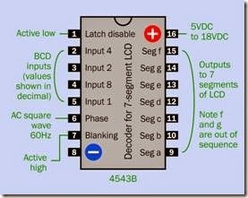
An alternative is to use a decoder chip such as the 4543B or 4056B, which receives a binary- coded decimal input (i.e., 0000 through 1001 bi- nary, on four input puts) and translates it into an output on seven pins suitable for connection with the seven segments of a 7-segment display. The 4543B requires a square-wave input to its “phase” pin. The square-wave must also be applied simultaneously to the backplane of the LCD, often identified as the “common” pin on datasheets. Pinouts for the 4543B are shown in Figure 17-16.

The 4543B includes provision for “display blanking,” which can be used to suppress leading zeros in a multidigit number. However, the lack of out- puts to control a minus sign or decimal point limits the decoder to displaying positive integers.

clip_image037

Figure 17-16. Pinouts for the 4543B decoder chip, which is designed to drive a seven-segment numeric LCD.

The power supply for a 4543B can range from 5VDC to 18VDC, but because the logic-high out- put voltage will be almost the same as that of the power supply, it must be chosen to match the power requirements of the LCD (very often 5VAC).((( To drive a three-digit numeric display module, a separate decoder chip can be used to control each digit. The disadvantage of this system is that each decoder requires three inputs, so that a three-digit display will require nine outputs from the microcontroller.

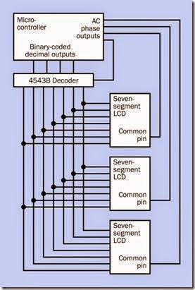
To deal with this issue, it is common to multiplex a multi-digit display. This means that each output from the decoder is shared among the same segments of all the LCD numerals. Each LCD numeral is then activated in sequence by applying AC voltage to its common pin. Simultaneously, the decoder sends the data appropriate to that LCD. This process must be fast enough so that all the digits appear to be active simultaneously, and is best managed with a microcontroller. A simplified schematic is shown in Figure 17-17. It can be compared with a similar circuit to drive LED displays, shown in Figure 24-13.

Alphanumeric Display Module

Arrays of dot-matrix LCDs that can display alphabetical characters as well as numerals require preset character patterns (usually stored in ROM) and a command interpreter to process instructions that are embedded in the data stream. These capabilities are often built into the LCD module itself.

While there is no formal or de facto standard, the command set used by the Hitachi HD44780 controller is installed in many displays, and code libraries for this set are available for download from sites dedicated to the Arduino and other microcontrollers. Writing code from scratch to control all aspects of an alphanumeric display is not a trivial chore. The Hamtronix HDM08216L-3- L30S is a display that incorporates the HD44780.

clip_image039

Figure 17-17. When two or more numeric displays are multiplexed, a control device (typically, a microcontroller) activates each of them in turn via its backplane (common terminal) while sending appropriate data over a shared bus.

Regardless of which standard is used, some features of alphanumeric display modules are al- most universal:

• Register select pin. Tells the display whether the incoming data is an instruction, or a code identifying a displayable character.

• Read/write pin. Tells the display whether to receive characters from a microcontroller or send them to a microcontroller.

• Enable/disable pin.

• Character data input pins. There will be eight pins to receive the 8-bit ASCII code for each displayable character in parallel. Often there is an option to use only four of these pins, to reduce the number of microcontroller out- puts necessary to drive the display. Where four pins are used, each 8-bit character is sent in two segments.

• LED backlight pin. Two may be provided, one connected to the anode(s) of the LED back- light, the other to the cathode(s).

• Reset pin.

Embedded instruction codes can be complex, including commands to reposition the cursor at a specific screen location, backspace-and-erase, scroll the display, and erase all characters on the screen. Codes may be included to adjust screen brightness and to switch the display between light-on-dark (negative) and dark-on-light (positive) characters.

Some display modules also have graphics capability, allowing the user to address any individual pixel on the screen.

Because of the lack of standardization in control codes, manufacturer’s datasheets must be consulted to learn the usage of a particular alpha- numeric display module. In addition to data- sheets, online user forums are a valuable source of information regarding quirks and undocumented features.

What Can Go Wrong
Temperature Sensitivity

Liquid crystals vary in their tolerance for low and high temperatures, but generally speaking, a higher voltage may be necessary to create a sufficiently dense image at a low temperature. Conversely, a lower voltage may be necessary to avoid “ghosting” at a high temperature. An absolutely safe operating temperature range is likely to be 0 through 50 degrees Celsius, but check the manufacturer’s datasheet for confirmation. Special-purpose LCDs are available for extreme temperatures.

Excessive Multiplexing

A twisted nematic display is likely to perform poorly if its duty cycle is greater than 1:4. In other words, more than four displays should not be multiplexed by the same controller.

DC Damage

An LCD can be damaged quickly and permanently if it is subjected to DC current. This can occur by accident if, for example, a timer chip is being used to generate the AC pulse stream, and the timer is accidentally disconnected, or has an incorrect connection in its RC network. Check timer output with a meter set to measure AC volts before allowing any connection to the common pin of an LCD.

Bad Communications Protocol

Many alphanumeric display modules do not use a formal communications protocol. Duplex serial or I2C connection may not be available. Care must be taken to allow pauses of a few milliseconds after execution of embedded commands, to give the display sufficient time to complete the instruction. This is especially likely where a command to clear all characters from the screen has to be executed. If garbage characters appear on the screen, incorrect data transfer speed or lack of pause times may be to blame.

Wiring Errors

This is often cited by manufacturers as the most common cause of failure to display characters correctly, or lack of any screen image at all.


decoder:What it Does,Input Devices,LED Driver,Schematic Symbol,Similar Devices,How It Works,Variants,Values,How to Use It,What Can Go Wrong,Glitches,Unhelpful Classification and Active-Low and Active-High.

decoder

In this Encyclopedia, a decoder is a digital chip that receives a binary-coded input and converts it to a decimal output by applying a logic state to one of a sequence of pins, each of which is assigned an integer value from 0 upward.

The term “decoder” also refers to components and devices that have other functions, such as decoding audio or video formats. These functions are not included here.

What it Does

A decoder receives a binary-coded number on two or more input pins. It decodes that number and expresses it by activating one of at least four output pins.

The behavior of a decoder with a two-bit binary input is shown in four sequential snapshots in Figure 15-1, where the least significant bit of the input is on the right in each diagram, and the output moves from right to left.

Figure 15-2 shows a similar sequence in a decoder where various values of a three-bit input are decoded to create an eight-pin output.

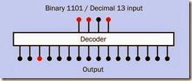
One sample state of a four-bit decoder is shown in Figure 15-3.

All of these figures assume that a high state rep- resents an active input or output. In a few chips, a low state is used to represent an active output.

Decoders with 2, 3, or 4 input pins are common. To handle a binary input greater than 1111 (decimal 15), decoders can be chained together, as described below.

Manufacturers’ datasheets often describe de- coders in terms of their inputs and outputs. Typ- ical examples would include:

• 2-to-4 decoder (two input pins, four output pins)

• 3-to-8 decoder (three input pins, eight out- put pins)

• 4-to-10 decoder (for converting binary- coded decimal to decimal output)

• 4-to-16 decoder (also known as a

hex decoder).

Input Devices

The input pins of a decoder can be driven by a counter that has a binary-coded output. A de- coder can also be driven by a microcontroller, which may have an insufficient number of out- put pins to control a variety of devices. Two, three, or four of the outputs can be used to rep- resent a binary number which is passed through the decoder to activate the devices one at a time, perhaps with transistors or Darlington arrays introduced to handle the load. This is suggested in Figure 15-4.

A shift register can be used for a similar purpose, but often has only one pin for input. This pin must be supplied sequentially with a serial pattern of bits that will match the desired high/low states of the output pins. The relative advantage of this system is that a shift register can generate any pattern of output states. A one- of-many decoder can activate only one output at a time.

LED Driver

A special case is a seven-segment decoder de- signed to drive a seven-segment LED display numeral. A binary-coded decimal number on four input pins is converted to a pattern of out- puts appropriate for lighting the segments of the display that will form a number from decimal 0 through 9.

Schematic Symbol

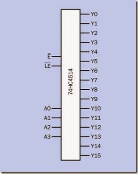
Like other logic-based components, the decoder does not have a specific schematic symbol and is represented by a plain rectangle as in Figure 15-5, with inputs on the left and outputs on the right. The bars printed above the E and LE abbreviations (which stand for Enable and Latch Enable, respectively) indicate that they are active-low. In this chip, the 74HC4514, all outputs are active-high, but in a related 4-to-16 decoder, the 74HC4515, all outputs are active-low. In both of these chips, the Enable pin is held low to activate the outputs. The Latch Enable pin freezes the current state of the outputs (i.e., it latches them) when it is held low.

Generally speaking, pins labeled A0, A1, A2… in a datasheet are often the binary inputs (although A, B, C… may be used), with A0 designating the least significant bit. Outputs are usually labeled Y, and are activated in sequence from Y0 when the binary input starts counting upward.

Similar Devices

The similarities and differences between encoder, decoder, multiplexer, and demultiplexer can cause confusion.

• In a decoder, a binary number is applied as a pattern of logic states on two or more input pins. This value determines which one of four or more output pins will have an active logic state, while the rest remain in an inactive logic state.

• A multiplexer can connect a choice of multiple inputs to a single output, for data transfer. The logic state of an enable pin, or a bi- nary number applied as a pattern of logic states to multiple control pins, chooses which input should be connected with the output pin. The alternative term data selector evokes the function of this device more clearly.

• An analog multiplexer may allow its inputs and outputs to be reversed, in which case it becomes a demultiplexer. It can connect a single input to one of multiple outputs, for data transfer. The logic state of an enable pin, or a binary number applied as a pattern of logic states to multiple control pins, chooses which output should be used. The alternative term data distributor evokes the function of this device more clearly.

clip_image005

Figure 15-1. A decoder with two input pins can interpret their binary-number representation to create an active logic state on one of four output pins.

clip_image007

Figure 15-2. A decoder with three input pins can interpret their binary-number representation to create a high logic state on one of eight output pins.

clip_image009

Figure 15-3. A decoder with four input pins can interpret their binary-number representation to create a high logic state on one of 16 output pins. Only one of the 16 possible states is shown here.

clip_image011

Figure 15-4. Four outputs from a binary counter or micro- controller can be used by a decoder to activate one of up to 16 output devices.

A photograph of a 74HC4514 decoder chip appears in Figure 15-6.

clip_image013

Figure 15-5. While no specific schematic symbol exists for a decoder chip, this style is commonly used. Shown here is a 4-to-16 decoder.

clip_image015

Figure 15-6. The 24-pin 74HC4514 decoder chip process- es a 4-bit input and represents it by making one of its 16 output pins active-high.

How It Works

A decoder contains logic gates, each of which is wired to respond to a unique binary pattern of inputs. (In the case of a seven-segment decoder, the internal logic is more complicated.) Figure 15-7 shows the logic of a 2-to-4 decoder. The darker blue area contains the components inside the chip. The external switches are included only to clarify the function of the decoder. An open switch is imagined to provide a low logic input, while each closed switch provides a high logic input.

Unlike ripple counters, where propagation de- lays can reduce the overall response time of the component, decoders function within two or three nanoseconds.

Variants

Decoder variants have not proliferated with time, and relatively few are available. Most are 3-to-8, 4-to-16, and binary-coded-decimal types.

The 7447 and 74LS47 are seven-segment decoders that have an open-collector output capable of driving a 7-segment display directly. The 7448 is similar but also contains built-in resistors and a capability to blank out leading zeros in a dis- play. However, some suppliers now list the 74LS48 as obsolete. It may be still available from old stock, but should not be specified in new circuits.

clip_image018

Figure 15-7. A simplified simulation of the logic in a de- coder. An actual chip would have an Enable line to activate the output. The dark blue rectangle indicates the space inside the chip.

Although 74LS47 is still being manufactured, and is available in surface-mount as well as through-hole format, a version is not available in the widely used HC family of 74xx chips. Care must be taken to satisfy the input voltage requirements of the 74LS47 when driving it with 74HCxx chips.

Values

As is the case with other logic chips, most de- coders in the through-hole 74xx series are in- tended for 5VDC power supply while the older 4000 series may tolerate up to 18VDC. Surface- mount versions may use voltages as low as 2VDC.

See the section on logic gates in Chapter 10 for a discussion of acceptable high and low input states. On the output side, the 4000 series chips are able to source or sink less than 1mA at 5VDC, but the 74HCxx series can manage around 20mA.

How to Use It

The original applications for decoders in computer circuits have become uncommon, but the chips can still be useful in small appliances and gadgets where multiple outputs are controlled by a counter or microcontroller.

Although 16 is usually the maximum number of outputs, some chips are designed to allow expansion. The 74×138 (where a chip family identifier such as LS or HC can be substituted for the letter x) is a 3-to-8 decoder with two logic-low Enable pins and one logic-high Enable. If a value-8 binary line is applied to the low-enable of one chip and the high-enable of another, the first chip will be disabled when the line goes high to indicate that the binary number 1000 has been reached, and the second chip can continue up- ward from there by sharing the same three less- significant-bit inputs. As many as four chips can be chained in this way.

What Can Go Wrong

Problems that are common to all digital chips are summarized in the section on logic gates in “What Can Go Wrong” on page 105.

Glitches

Although a decoder typically functions faster than a ripple counter, it suffers the same tendency to introduce brief glitches in its output. These are momentary invalid states which occur while processes inside the chip that are slightly slower are catching up with other processes that reach completion slightly faster. A brief settling time is necessary to ensure that the output is stable and valid. This will be irrelevant when powering a de- vice such as an LED indicator, which will not display such brief transients. The problem may be more important if the output from the de- coder is used as an input to other logic chips.

If the input to a decoder is derived from a ripple counter, the input may also contain glitches, which can cause erroneous outputs from the de- coder. It is better to use a synchronous counter on the input side of a decoder.

Unhelpful Classification

Online parts suppliers tend to list decoders un- der the same category heading as encoders, multiplexers, and demultiplexers, making it difficult to find what you want. Under this broad subject heading (which will include thousands of chips), if you search by selecting the number of inputs relative to the number of outputs that you have in mind, this will narrow the search considerably.

Active-Low and Active-High

Chips with identical appearance and similar part numbers may have outputs that are either active-low or active-high. Some may offer a latch-enable pin, while others have enable pins that must be pulled low or forced high to pro- duce an output. Accidental chip substitution is a common cause of confusion.


multiplexer:What It Does,Differential Multiplexer,Similar Devices,How It Works,Schematic Symbol,Pin Identifiers,Variants,Values,How to Use It,Other Application Notes,What Can Go Wrong,Pullup Resistors and Break Before Make.

multiplexer

May be abbreviated as a mux (this term is sometimes printed all in caps), and may be referred to alternatively as a data selector. Some sources maintain that a multiplexer has no more than two channels, whereas a data selector has more, but there is no consensus on this, and datasheets continue to use the term “multiplexer” predominantly.

Analog multiplexers are usually bidirectional, and thus will function equally well as de- multiplexers. Consequently, this encyclopedia does not contain a separate entry for de- multiplexers.

What It Does

A multiplexer can select one of two or more input pins, and connect it internally with an output pin. Although it is an entirely solid-state device, it be- haves as if it contains a rotary switch in series with a SPST switch, as shown in Figure 16-1. A binary code applied to one or more Select pins chooses the input, and an Enable pin establishes the connection with the output. The Select and Enable functions are processed via an internal section referred to as a decoder, not to be con- fused with a decoder chip, which has its own entry in this encyclopedia.

All multiplexers are digitally controlled devices, but may be described as either digital or analog depending how they process the input signal. A digital multiplexer creates an output that is adjusted to logic-high or logic-low within the limits of its logic family. An analog multiplexer does not impose any processing on the voltage, and passes along any fluctuations. Thus, it can be used with alternating current.

image

Figure 16-1. A multiplexer functions as if it contains a rotary switch. The switch position is determined by a binary number applied to external Select pins. The internal connection is completed by applying a signal to an Enable pin.

Because an analog multiplexer merely switches a flow of current, it can be bidirectional; in other words, it can function as a demultiplexer, in which case the input is applied to the pole of the (imaginary) internal switch and outputs are taken from the terminals.

Differential Multiplexer

A differential multiplexer contains multiple switches that are differentiated from one anoth- er (i.e., they are electrically isolated, although they are controlled by the same set of select pins). A differential multiplexer is conceptually similar to a rotary switch with two or more decks con- trolled by a single shaft. See Figure 16-2.

clip_image007

Figure 16-2. A differential multiplexer contains two or more electronic switches that are differentiated from one another, similarly to the decks on a rotary switch. Al- though the channels into each switch are typically numbered from 0 upward, the switches are numbered from 1 upward.

A bidirectional dual 4-channel differential analog multiplexer is shown in Figure 16-3.

Modern multiplexers are often found switching high-frequency data streams in audio, telecommunications, or video applications.

Similar Devices

The similarities and differences between multiplexer, demultiplexer, encoder, and decoder can cause confusion:

• A multiplexer can connect a choice of multiple inputs to a single output, for data transfer. The logic state of an enable pin, or a bi- nary number applied as a pattern of logic

states to multiple control pins, chooses which input should be connected with the output pin. The alternative term data selector evokes the function of this device more clearly.

• An analog multiplexer may allow its inputs and outputs to be reversed, allowing it to become a demultiplexer, connecting a single input to one of multiple outputs, for data transfer. The logic state of an enable pin, or a binary number applied as a pattern of logic states to multiple control pins, chooses which output should be used. The alternative term data distributor evokes the function of this device more clearly.

clip_image009

Figure 16-3. This CMOS chip contains two four-channel differential analog multiplexers.

• In an encoder, an active logic state is applied to one of four or more input pins, while the rest remain in an inactive logic state. The in- put pin number is converted to a binary code which is expressed as a pattern of logic states on two or more output pins.

• In a decoder, a binary number is applied as a pattern of logic states on two or more input pins. This value determines which one of four or more output pins will have an active logic state, while the rest remain in an inactive

logic state. A digital multiplexer does not al- low reversal of its inputs and outputs, but a decoder functions as if it were a digital de- multiplexer.

How It Works

The multiple inputs to a multiplexer are referred to as channels. Almost always, the number of channels is 1, 2, 4, 8, or 16. A 1-channel component is only capable of “on” or “off” modes and functions similarly to a SPST switch.

If there are more than two channels, a binary number will determine which channel is con- nected internally. The number of channels is usually the maximum that can be identified by the number of select pins, so that 2 pins will control 4 channels, 3 pins will control 8 channels, and 4 pins (the usual maximum) will control 16 channels.

In multiplexers with three or more channels, an enable pin is usually still present to activate or deactivate all the channels simultaneously. The enable feature may be described alternatively as a strobe, or may have an inverse function as an inhibit pin.

Although a rotary switch is helpful in conceptualizing the function of a multiplexer, a more common representation (sometimes in datasheets) is an array of SPST switches, each of which can be opened or closed by the decoder circuit. A typical example, depicting a dual differential multiplexer, is shown in Figure 16-4. Note that the internal decoder can only close one switch in each channel at a time.

The switch analogy is appropriate in that when an output from a multiplexer is not connected internally (i.e., its switch is “open”) it is effectively an open circuit. However, some multiplexers contain pullup resistors to give each output a de- fined state. This can be an important factor in determining whether the multiplexer is suitable for a particular application.

clip_image011

Figure 16-4. The internal function of a dual multiplexer is commonly represented as a network of SPST switches, each of which is controlled by decoder logic.

A digital multiplexer actually contains a network of logic gates, shown in simplified form in Figure 16-5.

A demultiplexer has internal logic shown in simplifier form in Figure 16-6.

Schematic Symbol

In a schematic, a multiplexer and demultiplexer may be represented by a trapezoid with its longer vertical side oriented toward the larger number of connections. This is shown in Figure 16-7. However, this symbol is falling into disuse.

More often, as is the case with most logic components, a multiplexer or demultiplexer is represented by a rectangle with inputs on the left and

outputs on the right, as shown in Figure 16-8. The distinction between inputs and outputs is problematic, however, in an analog multiplexer which will allow data flow to be reversed.

clip_image013

Figure 16-5. A simplified representation of the logic gates in a digital multiplexer.

clip_image015

Figure 16-6. A simplifier representation of the logic gates in a digital demultiplexer.

Pin Identifiers

The lack of standardization in the identification of pin functions is perhaps more extreme in the case of multiplexers than for other types of logic chips.

clip_image017

Figure 16-7. The traditional symbol for a multiplexer (left) and demultiplexer (right). The trapezoid is oriented with its longer vertical side facing the larger number of connections. This symbol is falling into disuse.

clip_image019

Figure 16-8. A simple rectangle is most often used as a schematic symbol for a multiplexer, but the abbreviations assigned to pin functions are not standardized. See text for details.

An output enable pin will be shown as E or EN, or occasionally OE. It may alternatively be de- scribed as an inhibit pin, labeled INH, or some- times will be called a strobe. The function is the same in each case: one of its logic states will en- able the internal switches, while its other logic state will prevent any internal switches from closing.

Switch inputs may be labeled S0, S1, S2… or X0, X1, X2… or may simply be numbered, almost al- ways counting up from 0. Where two or more sets of switches coexist in one package, each set of inputs may be distinguished from the others by preceding each identifier with a numeral or letter to designate the switch, as in 1S0, 1S1, 1S2… or 1X0, 1X1, 1X2… (Switches are generally numbered from 1 upward, even though their inputs are numbered from 0 upward.) Outputs may be identified using the same coding scheme as in- puts, bearing in mind that the inputs and outputs of an analog multiplexer usually are interchangable. Some manufacturers, however, prefer to identify each multiplexer output by preceding it with letter Y. Alternatively, Z1, Z2, Z3… may identify the outputs from switches 1, 2, 3… Fortunately, datasheets usually include some kind of key to this grab-bag of abbreviations.

Control pins are often identified as A, B, C… with letter A representing the least significant bit in the binary number that is applied to the pins.

Voltages can be confusing in multiplexers. Components intended for use with digital inputs are straightforward enough, as the supply voltage will be identified as VCC and is typically 5VDC for through-hole packages (often lower for surface- mount), while negative ground is assumed to be 0VDC. However, where a multiplexer may be used with AC inputs in which the voltage varies above and below 0V, supply voltages above and below 0VDC are also possible—such as +7.5VDC and −7.5VDC, to take a random example. Three power-supply pins may be provided for this purpose. The positive supply will usually be identified as VDD (the D refers to the Drain in the internal MOSFETs). A VEE pin may be at 0VDC or at a negative value equal and opposite to VDD. The E in this abbreviation is derived from Emitter voltage, even though the component may not contain a bipolar transistor with an emitter. Customarily, a VSS pin (the S being derived from the Source in the internal MOSFETs) will be at 0VDC, and other voltages will be measured above and below this baseline. This ground pin may alternatively be labeled GND.

As is customary in logic chips, low-active control pins will have a bar printed above their identifiers, or an apostrophe will be placed after an identifier if the font does not permit printing the bar. Alternatively, low-active pins may be represented by showing a small circle, properly referred to as a bubble, at the input or output point of the symbol for the multiplexer. Note that analog in- puts and outputs are neither high-active nor low- active; they merely pass voltages through.

Variants

Most multiplexers are “break before make” devices, where one input is disconnected before the next input is connected. However, some exceptions exist, and datasheets should be checked for this. It can be a significant issue, because make- before-break switching will briefly connect external devices with each other, through the chip.

Many multiplexers can tolerate control voltages above the usual high value in a logic circuit—as high as 15VDC in some cases. The voltage that is switched by the multiplexer may be the same as the control voltage, or may be higher.

Some analog multiplexers have overvoltage protection that allows them to withstand input voltages that are twice or three times the recommended maximum.

Datasheets may mention “internal address de- coding,” meaning that the binary number input, specifying a channel to be switched, is decoded inside the chip. In fact, virtually all multiplexers now have on-chip address decoding, and this feature should be assumed to exist, regardless of whether it is mentioned.

Values

The voltage to be switched will usually be re- ferred to as the input voltage, VIN.

An analog multiplexer should not be subjected to current exceeding the value that it is designed to switch. This is known as the maximum channel current. A typical value would be 10mA, although many modern surface-mount components are designed for currents in the microamp range.

The on-resistance is the resistance imposed by the analog multiplexer on the signal flowing through it. While modern, specialized analog multiplexers may have an on-resistance as low as 5Ω, these are relatively unusual. An on-resistance of 100Ω to 200Ω is more common. This value will vary within a component depending on the power supply voltage and the voltage being switch- ed. It will increase slightly as VIN deviates above (or below) 0V, will increase substantially for lower values of supply voltage, and will increase significantly with temperature.

The curves in Figure 16-9 show on-resistance of an analog multiplexer varying with input volt- age, with three different power supplies: plus- and-minus 2.5VDC (described in the graph as a “spread” of 5VDC), plus-and-minus 5VDC (a “spread” of 10VDC), and plus-and-minus 7.5VDC (a “spread” of 15VDC). These curves were derived from a datasheet for the MC14067B analog multiplexer; curves for other chips will be different, although the basic principles remain the same.

Switching time is an important consideration in high-speed applications. The “on” and “off” times may be used, confusingly, to denote the on- resistance of each individual switch.

clip_image022

Figure 16-9. Variations in on-resistance in an analog multiplexer. Each voltage “spread” is the difference between positive supply voltage and an equal-and-opposite negative ground voltage. Thus a “spread” of 10VDC means plus and minus voltages of 5VDC. (Curves derived from On Semiconductor datasheet for MC14067B analog multiplexer.)

How to Use It

specified in a datasheet (often as tON and tOFF) are  a function of the propagation delay from the control input to the toggling of the switch, and are generally measured from the halfway point of the rising or falling edge of the control input, to the 90% point of the output signal level.

Leakage current is the small amount of current (often measured in picoamperes) that the solid- state switch will pass when it is in its “off” state. This should be insignificant except when very high-impedance loads are used.

Separate switches inside a multiplexer may have characteristics that differ slightly from one an- other. Differences in on-resistance between adjacent switches can be important when switch- ing parallel analog signals. A datasheet should mention the extent to which switches have matched characteristics, and may define the maximum deviation from one another using the abbreviation RON even though this same term

A multiplexer may be used as a simple switch to choose one of multiple inputs, such as a choice of input jacks on a stereo system. A dual differential multiplexer is useful in this application, as it can use a single select signal to switch two signal paths simultaneously.

A multiplexer can also be used as a digital volume control by switching an audio signal among a variety of resistances, similar to a digital potentiometer. In this application, the possible presence of pullup resistors inside the multiplexer must be considered.

Where a microcontroller must monitor a large number of inputs (for example, a range of temperature sensors or motion sensors), a multiplexer can reduce the number of input pins required. Its data-select pins will be cycled through all the possible binary states by the microcontroller, to select each data input in turn, while its single-wire output will carry the analog data to a separate pin on the microcontroller which performs an analog-digital conversion.

Conversely, a demultiplexer (i.e., an analog multiplexer such as the 4067B chip which can be used in demultiplexer mode) can be used by a microcontroller to switch multiple components on and off. Four outputs from the microcontroller can connect with the control pins of a 16-channel demultiplexer, counting from binary 0000 through binary 1111 to select output pins 0 through 15. After selecting each pin, the microcontroller can send a high or low pulse through it. The process then repeats. (A decoder can be used in the same way.)

Other Application Notes

Multiplexers may be cascaded to increase the inputs-to-outputs ratio.

Modern multiplexers are found on computer boards where they choose among video output ports, or as PCI express channel switches.

A multiplexer may be used as a parallel-to-serial converter, as it samples multiple channels and converts them into a serial data stream.

In telecommunications, a multiplexer can sample voice signals from multiple separate inputs and combine them into a digital stream that can be transmitted at a faster bit rate over a single channel. However, this application goes far be- yond the simple uses for multiplexers described here.

What Can Go Wrong

Problems that are common to all digital chips are summarized in the section on logic gates (see “What Can Go Wrong” on page 105).

Pullup Resistors

While they are often necessary to prevent connections from floating, pullup resistors built into a multiplexer may have unexpected consequences if the user is unaware of them.

Break Before Make

For most applications, it is desirable for each internal solid-state switch to break one connection before making a new one. This avoids the possibility of separate external components being briefly connected with each other through the multiplexer. Datasheets should be checked to verify that a multiplexer functions in break- before-make mode. If it doesn’t, the enable pin can be used momentarily to disable all connections before a new connection is established.

Signal Distortion

Where a multiplexer is passing analog signals, signal distortion can result if the on-resistance of multiple internal switches varies significantly at different voltages. A datasheet for an analog multiplexer should usually include a graph showing on-resistance over the full signal range. The flatter the graph is, the less distortion the component will create. This is often described in datasheets as RON Flatness.

Limits of CMOS Switching

Although most multiplexers are built around CMOS transistors, their switching speed may be insufficient for video signals, and their on- resistance may vary enough to introduce distortion. Multiplexers are available with complementary bipolar switching for very high-speed applications. They impose some penalties in cost and power consumption.

Transients

Switch capacitance inside a multiplexer can cause transients in the output when the switch changes state. An allowance for settling time may be necessary. This will be additional to the switching speed claimed by the datasheet.


encoder:What It Does,Schematic Symbol,Similar Devices,How It Works,Variants,Values,How to Use It,Cascaded Encoders and What Can Go Wrong.

encoder

In this encyclopedia, an encoder is a digital chip that converts a decimal-valued input into a binary-coded output.

The term “encoder” may alternatively refer to a rotational encoder (also known as a rotary encoder) which has a separate entry in Volume 1 of this encyclopedia. The term may also describe a code hopping encoder, which is an encryption device used in keyless entry systems for automobiles.

What It Does

An encoder is a logic chip that receives an input consisting of an active logical state on one of at least four input pins, which have decimal values from 0 upward in increments of 1. The encoder converts the active pin number into a binary value represented by logic states on at least two output pins. This behavior is opposite to that of a decoder.

Encoders are identified in terms of their inputs and outputs. For example:

• 4-to-2 encoder (four input pins, two output pins)

• 8-to-3 encoder (eight input pins, three out- put pins)

• 16-to-4 encoder (sixteen input pins, four out- put pins)

In the early days of computing, encoders processed interrupts. This application is now rare, and relatively few encoder chips are still being manufactured. However, they are still useful in small devices—for example, if a large number of inputs must be handled by a microcontroller that has insufficient pins to receive data from each individually.

Schematic Symbol

Like other logic-based components, the encoder does not have a specific schematic symbol and can be represented by a plain rectangle as in Figure 14-1, with inputs on the left and outputs on the right. The bars printed above some of the abbreviations indicate that an input or output is active-low. In this chip, the 74LS148, all inputs and outputs are active-low.

Generally speaking, inputs labeled D0, D1, D2… are used for data input, although they may simply be numbered, with no identifying letter. The encoded outputs are typically identified as Q0, Q1, Q2… or A0, A1, A2… with Q0 or A0 designating the least significant bit in the binary number.

Pins labeled E and GS are explained in the following section.

clip_image005

Figure 14-1. While no specific schematic symbol exists for an encoder chip, this style is commonly used. Shown here is a 16–to–4 encoder with active-low inputs and outputs.

Similar Devices

The similarities and differences between encoder, decoder, multiplexer, and demultiplexer can cause confusion.

• In an encoder, an active logic state is applied to one of four or more input pins, while the rest remain in an inactive logic state. The in- put pin number is converted to a binary code which is expressed as a pattern of logic states on two or more output pins.

• In a decoder, a binary number is applied as a pattern of logic states on two or more input pins. This value determines which one of four or more output pins will have an active logic state, while the rest remain in an inactive logic state.

• A multiplexer can connect a choice of multiple inputs to a single output, for data transfer. The logic state of an enable pin, or a bi- nary number applied as a pattern of logic states to multiple control pins, chooses which input should be connected with the output pin. The alternative term data selector evokes the function of this device more clearly.

• An analog multiplexer may allow its inputs and outputs to be swapped, in which case it becomes a demultiplexer. It can connect a single input to one of multiple outputs, for data transfer. The logic state of an enable pin, or a binary number applied as a pattern of logic states to multiple control pins, chooses which output should be used. The alternative term data distributor evokes the function of this device more clearly.

How It Works

An encoder contains logic gates. The internal logic of an 8-to-3 encoder is shown in Figure 14-2, where the darker blue rectangle rep- resents the chip. The switches in this figure are external and are included only to clarify the concept. An open switch is imagined to provide an inactive logic input, while a single closed switch provides an active logic input. (Multiple active inputs can be handled by a priority encoder, de- scribed below).

Each input switch has a numeric status from 1 to

7. The switch with value 0 does not make an internal connection, because the output from the OR gates is 000 by default.

The logic state of each OR output represents a binary number, weighted with decimal values 1, 2, and 4, as shown at the bottom of the figure. Thus, if switch 5 is pressed, by tracing the connections it is clear that the outputs of OR gates 4 and 1 become active, while the output from gate 2 remains inactive. The values of the active out- puts thus sum to 5 decimal.

Figure 14-3 shows the outputs for all possible in- put states of a 4-to-2 encoder. Figure 14-4 shows the outputs for all possible input states of an 8- to-3 encoder. These diagrams assume that a high logic state is an active logic state, on input or output. This is usually the case.

clip_image008

Figure 14-2. A simplified simulation of the internal logic of an 8-to-3 encoder. The dark blue rectangle indicates the space inside the chip. The external switches are in- cluded only to clarify the concept. An encoder chip would have an Enable line to create an active output.

clip_image010

Figure 14-3. The four possible inputs of a 4-to-2 encoder (top of each panel) and the encoded outputs (below).

clip_image012

Figure 14-4. The eight possible inputs of an 8-to-3 en- coder (at the top of each panel), and the encoded outputs (below). Note that one input of an encoder must always be logic-high. All logic-low inputs are not a valid state.

Unlike ripple counters, where propagation de- lays can reduce the overall response time of the component, decoders respond within two or three nanoseconds.

Variants

A simple encoder assumes that only one input pin can be logically active at a time. A priority encoder assigns priority to the highest-value input pin if more than one happens to receive an active input. It ignores any lower-value inputs. An ex- ample is the 74LS148, which is an 8-to-3 chip.

A few encoders feature three-state outputs (also known as tri-state), in which a high-impedance or “floating” output state is available in addition to the usual high and low logic states. The high- impedance state allows multiple chips to share an output bus, as those that are in high- impedance mode appear to be disconnected. This is useful if two or more encoders are cascaded to handle a larger number of inputs.

Values

As is the case with other logic chips, most en- coders in the through-hole 74xx series are in- tended for 5VDC power supply while the older 4000 series may tolerate up to 18VDC. Surface- mount versions may use voltages as low as 2VDC.

See the section on logic gates in Chapter 10 for a discussion of acceptable high and low input states. On the output side, the 4000 series chips are able to source less than 1mA at 5VDC, but the 74HCxx series can manage around 20mA.

How to Use It

Suppose that a microcontroller should respond to an eight-position rotary switch. Because the switch cannot be turned to more than one position at a time, all of its eight contacts can be connected with the inputs on an encoder, which will deliver a 3-bit binary number to three inputs of the microcontroller. Code inside the microcontroller then interprets the pin states.

This is shown in Figure 14-5. Pulldown resistors would be needed on the input pins of the en- coder, to prevent them from floating when they are not connected by the rotary switch. They have been omitted from this diagram for simplicity. Debouncing the switch would be handled by the microcontroller.

Other forms of input may be used instead of a rotary switch. For example, the outputs from eight comparators or eight phototransistors could be passed through an encoder.

clip_image016

Figure 14-5. Output from an eight-input rotary switch could be connected through an 8-to-3 encoder to provide input to a microcontroller using a reduced number of pins. Pulldown resistors have been omitted for simplicity.

Cascaded Encoders

Encoders are often provided with features to facilitate handling additional inputs via multiple chips. Typically, a second Enable pin is provided, as an output that connects with the Enable input of the preceding chip. This preserves the priority function, so that an input on the second chip prevents any additional input to the first chip from affecting the output. In a datasheet, the en- able pins may be labeled EIN and EOUT, or EI and EO.

In addition, a GS pin will be included, meaning “Group Select.” It is logically active only when the encoder is enabled and at least one input is active. The GS pin of the most-significant encoder provides an additional binary digit.

The outputs from two encoders can be linked via OR gates, as shown in Figure 14-6, where the lower chip’s GS output provides the most significant bit of a four-bit binary number.

clip_image018

Figure 14-6. Two eight-bit encoders can be cascaded to handle 16 separate inputs. In this example, the encoders use active-high logic.

What Can Go Wrong

Problems that are common to all digital chips are summarized in the section on logic gates in “What Can Go Wrong” on page 105.

See “What Can Go Wrong” on page 149 in the entry describing decoders for a list of more specific problems that also afflict encoders.