vacuum-fluorescent display:What It Does,How It Works,Anode, Cathode, and Grid,How to Use It,Modern Application,Variants,Color,Character Sets and Pictorial Design,Comparisons,What Can Go Wrong and Fading.

vacuum-fluorescent display

The term vacuum-fluorescent display is seldom hyphenated, but the first two words are hyphenated here as they constitute an adjectival phrase. The acronym VFD is be- coming increasingly popular, although it is ambiguous, being also used to identify a variable frequency drive. In both instances, the acronym is printed without periods be- tween the letters.

The entry in this encyclopedia dealing with fluorescent lights does not include VFDs, because their purpose and design are very different. A VFD is an informational display, often showing numerals and letters, while a fluorescent light merely illuminates a room or work area. Although a VFD does use fluorescent phosphors, they are printed onto light-emitting segments of the display instead of being applied to the inside surfaces of a glass envelope.

What It Does

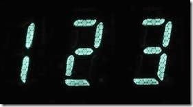
A vacuum-fluorescent display or VFD superficially resembles a backlit monochrome LCD or an LED display, as it can represent alphanumeric characters by using segments or a dot matrix, and can also display simple shapes. It is often brighter than the other information display systems, and can emit an intense green phosphorescent glow that some people find aesthetically pleasing, even though a grid of very fine wires is superimposed internally over the displayed image.

There is no specific schematic symbol to represent a vacuum-fluorescent display.

How It Works

The display is mounted inside a sealed capsule containing a high vacuum. A widely spaced series of very fine wires, primarily made of tungsten, functions as a cathode, moderately heated to en- courage electron emission. The wires are often referred to as filaments.

A fluorescent light uses AC, and both of its electrodes are often confusingly referred to as cathodes. A VFD uses DC, and its cathode array has the function that one would expect, being connected with the negative side of the DC power supply.

Opposite the cathode, just a few millimeters away, is an anode that is subdivided into visible alphanumeric segments, symbols, or dots in a matrix. Each segment of the anode is coated with phosphors, and individual segments can be separately energized via a substrate. When electrons strike a positively charged anode segment, it emits visible light in a process of fluorescence. This behavior can be compared with that of a cathode-ray tube. However, the cathodes in a VFD are efficient electron emitters at a relatively low temperature, while the cathodes in a cathode- ray tube require substantial heaters.

Anode, Cathode, and Grid

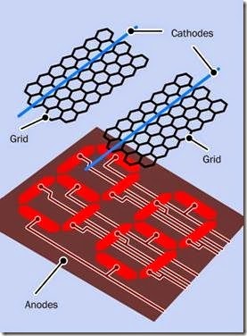
A grid consisting of a mesh of very fine wires is mounted in the thin gap between the filaments of the cathode and the segments of the anode. A simplified view of this arrangement is shown in Figure 25-1.

clip_image006

Figure 25-1. The basic elements of a vacuum-fluorescent display.

The polarity of the charge on the grid controls and diffuses electrons emitted by the cathode. If a grid section is negatively charged, it repels electrons and prevents them from reaching the

sections of the anode beneath it. If the grid section is positively charged, it encourages electrons to reach the anode. Thus, the grid functions in the same way as the grid in a triode vacuum tube, but its conductors are so thin, they are barely visible.

How to Use It

Electronic calculators used vacuum-fluorescent displays during the 1970s, before LED displays and LCDs became more competitive. Purely nu- meric VFD modules are still available as strings of digits, although they are becoming uncommon and have been replaced by alphanumeric dot- matrix modules where each VFD character is mounted in its own glass module on a separate substrate.

Figure 25-2 shows the interior of a Commodore calculator from the 1970s, with its nine-digit vacuum-fluorescent display enclosed in one glass capsule.

clip_image009

Figure 25-2. The vacuum-fluorescent display from a 1970s Commodore calculator.

A closeup of three digits from the previous figure appears in Figure 25-3, showing the grid super- imposed above each numeral.

clip_image011

Figure 25-3. Three digits from the previous figure, showing the grid that controls their illumination.

A tinted filter of the same color as the display is usually placed in front of it, to conceal some of its workings. Thus, the Commodore calculator used a green filter in front of its green numerals. Figure 25-4 shows two seven-segment numerals from another device, with the filter removed. This reveals not only the grid but also the horizontal wires that function as the cathode. Connections between the segments of the numerals and a backplane are also visible.

clip_image013

Figure 25-4. Seven-segment numerals viewed without a colored filter, revealing the cathode (horizontal wires) and the grid (wire mesh).

Modern Application

A modern VFD module is likely to be mated with a driver that converts 5VDC to the higher voltage (typically 50VDC to 60VDC) required for the dis- play. Built-in logic may offer the option to receive data via an 8-bit parallel bus or with SPI serial protocol, and will contain a character set. A typical display resolution is 128 x 64 pixels.

The combination of a grid and a segmented anode enables a VFD to be controlled by multiplexing. For instance, in a display of four seven- segment numerals, the same equivalent segments in all four numerals can be connected in parallel while a separate grid covers each numeral. When each grid is positively energized, it se- lects the corresponding numeral, and the on-off segment patterns appropriate to that numeral are supplied. This procedure is repeated for each numeral in turn. Persistence of vision makes it appear that they are all active simultaneously.

Variants
Color

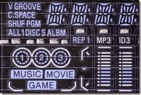
Although a VFD cannot provide a full-color display, selected anode segments can be coated with different phosphor colors, which can fluoresce simultaneously. Two or three individual colors are typically used, as in the display for a CD player where color helps to distinguish a variety of different functions. A closeup of a portion of the display from a CD player (with color filter re- moved) appears in Figure 25-5.

clip_image016

Figure 25-5. The lefthand section of a vacuum- fluorescent display from a CD player.

Character Sets and Pictorial Design

In the past, VFDs have combined seven-segment numerals in the same display as custom-shaped anodes. Solid-state gain meters in an audio amplifier, for instance, have used numerals beside a pictorial representation of gain levels resembling analog meters. The look and layout of a display of this type has been unique to a particular product.

Modern VFDs tend to use a generic dot-matrix display in which a character set in firmware dic-tates how patterns of dots are grouped to form numbers, letters, symbols, or icons.

The appearance of character sets generated with generic segments and dot-matrix arrays is thoroughly discussed and illustrated in the entry de- scribing liquid-crystal displays in Chapter 17. VFD alphanumeric modules are identical in vis- ual design to LCD modules, even though the internal electronics are different.

Comparisons

Two advantages of a VFD are that it functions well at low temperatures (unlike an LCD) and has sufficient brightness and contrast to be usable in sunlight (unlike many LED displays). It can be viewed from almost any angle.

Typical applications have included digital instrumentation in automobiles, information displays in audio and video consumer-electronics equipment, and numerical readouts in vending ma- chines, medical devices, and some digital clocks.

Because a VFD requires a relatively high voltage, has significant power consumption, can show only a limited range of fixed colors, and is more expensive than LED displays or LCDs, its popularity has declined since the end of the 1990s.

What Can Go Wrong
Fading

VFDs gradually fade with age, as a result of reduced electron emission from the electrodes or diminishing performance of the phosphor coatings. Increasing the working voltage can prolong the life of a display.


LED area lighting:What It Does,Trends in Cost and Efficiency,Schematic Symbol,How It Works,Visible Differences,Side-by-Side Comparison,Heat Dissipation,Efficacy,Dimming,Ultraviolet Output,Color Variation and Variants.

LED area lighting

The term LED area lighting is used in this encyclopedia to describe a white LED source that is bright enough to illuminate rooms, offices, or outdoor areas. It may also be used in desk lamps or table lamps as task lighting. LEDs for these purposes may be categorized as high-brightness, high-power, high-output, or high-intensity. A complete fixture containing at least one light source is properly known as a luminaire, although the term is not uniformly applied and is sometimes written incorrectly as a luminary.

The full term light-emitting diode is not normally applied to an LED used for area lighting. For this purpose, the LED acronym has become universal. Periods are not normally placed between the letters.

While an LED area-lighting package may contain more than one diode, it is still categorized here as a single source. By contrast, any component consisting of multiple separately discernible light-emitting diodes, as in a seven-segment numeral, a 14- and 16- segment alphanumeric character, a dot-matrix character, or a display of multiple characters, is listed in a separate entry as an LED display.

The term OLED is an acronym for Organic Light-Emitting Diode, a thin panel in which an organic compound is contained between two flat electrodes. Despite its functionality as a form of LED, its design is similar to that of thin-film electroluminiscent light sources. Therefore it is discussed in the entry on electroluminescence.

What It Does

High-brightness white LEDs provide a plug- compatible alternative to incandescent lamps, halogen lighting, and fluorescent lights for work spaces and the home.

At the time of writing, products are still evolving rapidly in the field of LED area lighting. A shared goal of manufacturers is to increase efficiency while reducing retail price to the point where high-brightness LEDs will displace fluorescent tubes for most low-cost lighting applications.

A wall-mounted LED reflector-bulb that emulates a halogen fixture is shown in Figure 23-1. A small LED floodlight for exterior use is shown in Figure 23-2. An early attempt to package an LED area light in a traditional-style bulb is shown in Figure 23-3. Within a decade, as LED area lighting continues to evolve, some of these examples

may look quaint. Configurations are evolving, with final results that remain to be seen.

clip_image005

Figure 23-1. A small LED reflector-light emulating a halo- gen fixture. Note the square of yellow phosphors mounted on the diode.

clip_image007

Figure 23-2. A floodlight for exterior use. Nine LEDs are assembled behind the yellow phosphors. The steel frame measures about 4” by 3”.

Trends in Cost and Efficiency

The luminous flux of a source is the total power that it radiates in all directions, within the visible spectrum. The unit that measures luminous flux is the lumen. For a more detailed discussion of

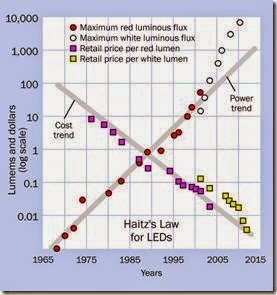
this topic, see “Power” on page 177. Since 1965, the cost per lumen of light from a given color of LED has decreased by about a factor of 10, while the maximum number of lumens emitted by an LED package has increased by a factor of 20, dur- ing each decade. This is known as Haitz’s Law, named after Dr. Roland Haitz of Agilent Technol- ogies. Figure 23-4 illustrates it graphically.

clip_image009

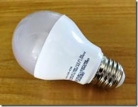
Figure 23-3. An LED light bulb. Unlike an incandescent bulb, it focuses the illumination in one direction, like a reflector-light. Consuming only 6W, it is claimed to be equivalent to a 40W incandescent bulb.

Schematic Symbol

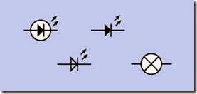
Schematic symbols that are commonly used to represent an LED are shown in Figure 23-5. The symbol remains the same regardless of the size or power of the component, but architectural plans may represent any type of light using the circle-and-X symbol at bottom right.

How It Works

A high-brighteness LED functions on the same basis explained in the entry describing LED in- dicators. Photons are emitted when electrons are sufficiently energized to cross a PN junction and combine with electron-holes.

An LED that appears white, or off-white, actually emits blue light that is re-radiated over a wide range of wavelengths by adding a layer of yellow phosphors to the chip. A cutaway diagram of an LED chip (properly known as a die), mounted un- der a silicone lens, is shown in Figure 23-6.

clip_image012

Figure 23-4. The increase in light output (luminous flux, in lumens) of a single LED compared with the decrease in cost-per-lumen during the years since 1965. The vertical logarithmic scale measures both dollars and lumens. Source: Philips Gardco site-lighting fact sheet with additional data from a “Strategies in Light Report” published by Semiconductor Equipment and Materials International in 2013.

clip_image014

Figure 23-5. The symbol for an LED remains the same re- gardless of its size and power, but architectural plans may use the circle-and-X symbol at bottom right for any type of light fixture.

LEDs are mass-produced by etching them into crystals that are then cut into wafers before being subdivided into dies, like silicon chips. Most of the blue LEDs that form the basis of white lighting use sapphire crystals as their substrate. The crystal may range in diameter from two inches to six inches. Large sapphire wafers are also finding potential applications in camera lens covers and scratch-resistant cover plates for cellular phones.

clip_image016

Figure 23-6. Cutaway diagram of a high-brightness white LED. Adapted from Philips Lumileds Technical Reference document.

While a die for an LED indicator may be 0.3mm x 0.3mm, a die in a high-brightness LED is often 1mm x 1mm. The size is limited by technical is- sues involving total internal reflection of the generated light.

The precise color of the light is adjusted by adding red phosphors to the yellow phosphors. This reduces the overall efficiency of the LED by around 10% but creates a “warmer” radiance. A graphical illustration of this principle is shown in Figure 22-3, in the entry on LED indicators.

The color temperature of white or offwhite light is measured in degrees Kelvin, typically ranging from 2,500K to 6,500K, where a lower number represents a light with more red in it and a higher number represents a light with more blue in it. This system of measurement was originally used with incandescent bulbs to define the temper- ature of the filament, which determined its color. See “Spectrum” on page 173 for a detailed ex- planation.

Visible Differences

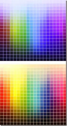
The effects of different types of illumination are compared in Figure 23-7. To create this figure, first a color chart was prepared in Photoshop and printed on high-gloss photo-grade paper with a Canon Pro9000 Mark II inkjet printer, which has separate colors for red and green in addition to cyan, pale cyan, magenta, pale magenta, yellow, and black.

The color chart was then photographed twice with a Canon 5D Mark II, using a fixed white balance of 4000K. The first exposure was made with “daylight spectrum” LED lighting (claimed color temperature of 6500K) while the second was made with halogen lighting (claimed color temperature of 2900K). The photographs were adjusted in Photoshop for levels only, to fill the available range of 256 values. The two exposures show how the same chart would appear when viewed under the different lights, if the human eye did not adjust itself at all. Note the large area of the LED exposure which is rendered in shades of blue or purple. Also note the dullness of the reds. This confirms the everyday belief that “day- light spectrum” LEDs tend to have a cold, purplish cast while incandescents have a warmer, yellow look.

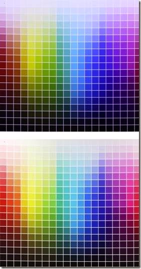
The same camera was then used to make two more exposures, this time with the white balance set to 6500 for LED lighting and 2900 for halogen lighting, which would be the recommended standard procedure, suggesting the kind of com- pensation that the human eye also tends to make for different ambient lighting. The result is shown at Figure 23-8. The LED version has improved, but the reds and yellows are still muted. The halogen version also looks better than before, but the magenta end of the spectrum has too much yellow in it. These images show the limits of white- balance correction for indoor photography.

clip_image018

Figure 23-7. The same printed color chart viewed with “daylight white” LEDs (top) and halogen lighting (bot- tom), without any compensation to allow for the different light spectra. A fixed white balance of 4000K was used for both pictures.

Side-by-Side Comparison

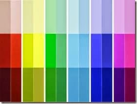
Because the human eye is much better at com- paring colors when they are adjacent to each other, another color chart was prepared using just six color bars of fully saturated red, yellow, green, cyan, blue, and magenta, with paler and darker versions above and below. The bars were separated with large white gaps. The chart was photographed first with the white balance set to 6500 under “daylight white” LED lighting and then again with the white balance at 2900 for halogen lighting. In Photoshop, the bars from the halogen version were copied and pasted beside the bars from the LED version to facilitate an A-B comparison. The result is shown in Figure 23-9.

clip_image020

Figure 23-8. The same color chart as before, photo- graphed with appropriate color temperature settings of 6500K (top, using “daylight-spectrum” LEDs) and 2900K (bottom, using halogen).

In each pair of colors, LEDs lit the one on the left, and halogen lights lit the one on the right. This figure shows the dramatic difference at the red end of the spectrum, and the poor reproduction of yellows by LED lighting. However, the LED rendering of green is better, and likewise the rendering of magenta, except where its darker version is concerned. Among the pale versions of the colors, the LED lights produce much less density (i.e., they have a brighter look) in the blues, greens, and cyans. The low densities will show up as pale highlights in a photograph of an object, and the picture will tend to have excessive co trast. This will also contribute to the “harsh” look of “daylight white” LED lighting which may be perceived by the eye.

clip_image022

Figure 23-9. A range of six fully saturated colors, with lighter and darker shades added above and below, photo- graphed first with “daylight spectrum” LEDs and then with halogen lights, after which the two sets of colors were paired for easy comparison. The LED version is on the left in each pair.

Halogen is deficient at the blue-violet end of the spectrum, even when the camera has an appropriate white-balance setting. Photographers can correct this using image-editing software. LED “daylight spectrum” lights are more difficult to correct. LEDs classified as “warm” should repro- duce reds better, but may not do so well with blues.

Diffuse light from a uniformly cloudy sky may be the most ideal form of lighting for photographing objects, but this is of little help for people who work (or take photographs) under artificial lights.

LED lights that contain separate red, green, and blue emitters may perform better, but create a different problem, in that shadows will tend to have color fringes caused by the small offsets between the colored emitters.

Heat Dissipation

An LED is less than 100% efficient because not all electrons mate with electron holes. Some man- age to bypass the semiconductor junction; some recombine without generating light; and some transfer their energy to other atoms. In each in- stance, waste heat is created. While the heat in an incandescent bulb is mostly dissipated by ra- diation, an LED must get rid of the heat almost entirely by conduction, typically through a heat sink. This complicates the design of a fixture, be- cause the integrity of the pathway to dispose of the heat must be retained when the LED bulb or tube is replaced.

Efficacy

The radiant luminous efficacy (LER) of an incandescent light source measures how effective it is at channeling its output within the visible spectrum instead of wasting it in infrared radiation. LER is expressed in lumens per watt, and in an incandescent bulb, it is calculated by dividing the power emitted in the visible spectrum (the luminous flux) by the power emitted over all wave- lengths. This is described in detail in “Efficacy” on page 179 in the entry dealing with incandescent lamps.

In an LED indicator, almost all the radiation can be contained within the visible spectrum, which suggests that its efficacy should be 100%. How- ever, because some waste heat is still created internally, the efficacy is calculated by dividing the light output, in lumens, by the power input, in watts, at the voltage required by the LED. (Lumens can be converted directly to watts, and therefore this division makes a comparison be- tween similar units).

In an LED lighting fixture that contains its own electronics to convert higher voltage AC to lower voltage DC, the power consumption of the fixture is measured not at the diode, but at the input side of the electronics. Therefore, the inefficiency of the electronics reduces the efficacy value of the lighting unit.

Dimming

An incandescent bulb is very sensitive to reduction in power. It becomes radically inefficient, emitting perhaps 1% of its normal light output if the power is reduced to 40%.

LEDs have an almost linear response to the sup- plied power. Usually a triac-based dimmer will not work well with LED area lighting, and a dimmer designed for LEDs must be substituted, using pulse-width modulation.

Ultraviolet Output

The gas plasma in a fluorescent light generates ultraviolet wavelengths that are shifted to the visible spectrum by the phosphor coating inside the glass envelope. Imperfections in the phosphor coating can potentially allow leakage of ultraviolet light, causing some researchers to claim that the use of CFLs (compact fluorescent lighting) for close-up work with desk lamps can in- crease the risk of developing some forms of skin cancer. (This claim remains controversial.)

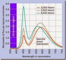
LED manufacturers are quick to point out that white LEDs do not emit any ultraviolet radiation. Figure 23-10 shows spectral power distribution curves derived from measurements of three high-brightness Color Kinetics LEDs manufactured by Philips. The manufacturer states categorically that “The LED-based color and white light products made by Color Kinetics do not emit outside the visible spectrum.” Infrared radiation is also negligible.

Color Variation

The correlated color temperature (CCT) is deter- mined by finding the conventional incandescent color temperature which looks most similar to the light from a white LED. Unfortunately, be- cause the CCT standard is insufficiently precise,

and because small manufacturing inaccuracies can occur, two LED sources with the same CCT number may still appear different when they are side by side. While the human eye adjusts itself to overall color temperature, it is sensitive to differences between adjacent sources. If two or more white LEDs in a lighting fixture do not have identical spectra, the difference will be noticeable.

clip_image024

Figure 23-10. Spectral power distribution curves for three high-brightness white LED lamps showing no ultraviolet emissions. (Adapted from a graph in a white paper published by Color Kinetics Incorporated.)

To address the issue, manufacturers introduced the concept of “binning,” in which lights are sub- classified to tighter specifications and are as- signed bin numbers based on their measured characteristics. The Philips Optibin system, for instance, assesses the light from various angles, as well as perpendicularly to the source. This is especially important where a large area such as a building lobby is painted white and is lit by high-brightness LEDs that must appear uniform in color temperature.

Variants

LED area lighting products are often designed to emulate the form factors of incandescent bulbs, halogen reflector bulbs, or fluorescent tubes. The standard screw-in base of an LED light bulb, the pin-base of a miniature 12V LED reflector bulb, and the pins on an LED tube enable easy migration to the newer technology.

Strip lights are unique to LED lighting systems. They are thick, flexible plastic ribbons in which are embedded a series of LEDs. For area lighting, the LEDs are white, and the strips can contain necessary control electronics for conversion of AC power. The strips can be placed behind ledges or moldings to provide soft, even illumination of the ceiling above.

Strip lights are also available for 12VDC power, to create lighting effects in customized automobiles and trucks. These strip lights are available in various colors in addition to white. Many have multicolor capability and can be controlled with a handheld remote.

Comparisons

The advantages of an incandescent lamp are listed in “Relative Advantages” on page 179, while advantages of fluorescent lights are listed in “Comparisons” on page 194. These lists can be compared with the following advantages for LED area lighting:

• While the life of an incandescent lamp for room lighting can be as little as 1,000 hours, LED area lighting typically claims up to 50,000 hours.

• The lifetime of an incandescent bulb is the average time it can emit light before cata- strophic failure. The lifetime of an LED is the average time it can emit light before gradu- ally dimming to 70% of its rated output. This is a much gentler, less inconvenient failure mode that does not require immediate re- placement.

• Unlike a fluorescent light or incandescent bulb, the LED does not contain hot tungsten that fails as a result of erosion.

• Unlike a fluorescent light, an LED does not contain mercury, and therefore does not re- quire special recycling arrangements that entail associated fees.

• While fluorescents can have difficulty starting in low temperatures, an LED is not sensitive to a cold environment.

• Bright LEDs are available in a wide range of colors that do not require filtering. Filters greatly reduce the efficiency of incandescent bulbs when they are used in applications such as traffic signals or rear lights on automobiles.

• High-brightness LEDs can be dimmable. Flu- orescent lights are usually not dimmable, or perform poorly in this role.

• LEDs are inherently directional, because the die radiates light at an angle of 90 degrees to its plane. This makes it ideal for ceiling mounting, where as much light as possible should be directed downward. A fluorescent tube or incandescent bulb often requires a reflector which reduces the overall efficiency.

• LEDs are insensitive to cycling. The life expectancy of an incandescent bulb or (especially) a fluorescent tube is reduced by cy- cling it on and off.

• No flickering. Fluorescent tubes may start to flicker as they age.

• No electrical interference. Fluorescent tubes can interfere with AM radio reception and some audio devices.

• Safe from breakage. LED area lighting does not necessarily use any glass.

However, high-brightness LEDs still have some barriers to overcome:

• Cost. In the United States, before 60W incandescent bulbs were legislated out of existence, they could be sold profitably for less than $1 each. A T8 fluorescent tube, measuring 1” diameter and 48” long, currently costs between $5 and $6 (retail) but has a life expectancy in the region of 25,000 hours, and uses only 20% of the power of an incan- descent bulb to generate two to three times as much light. Clearly the fluorescent tube is a more economical choice, despite the price of the electronics that must be included in the fixture to start the tube. By comparison, currently the purchase price of an LED tube is three times that of a fluorescent tube. It may last twice as long, but is not significantly more efficient, generating perhaps 100 lumens per watt while a fluorescent is typically capable of 90 lumens per watt. Prototype high-brightness LEDs have exceeded 200 lumens per watt, and should be competitive with fluorescents by 2020, but even then, migration will take time.

• Heat sensitivity. Heat reduces the light out- put and the lifespan of LED fixtures.

• Placement issues. Because LEDs are heat sensitive, they must be installed in locations that do not become excessively hot, their heat sinks must be correctly oriented, and they must have adequate ventilation.

• Color shift. Heat and age may cause the color temperature of an LED to shift slightly, as the color is usually derived from two types of phosphors.

• Nonuniformity. Manufacturing inconsistencies can cause LEDs of the same type to dis- play slightly different color temperatures. Fluorescents and incandescents are more uniform.

• Lower heat output than incandescents. While this is an advantage from the point of view of efficiency, it can be a disadvantage in applications such as traffic signals or air- port runway lighting where waste heat can help to keep the lights free from snow or ice.

Values

Although the output from an LED area light is directional, while the output from an incandes- cent bulb or a fluorescent light is omnidirection- al, the intensity is measured the same way in each instance, using lumens. This unit expresses the total light emission, without taking directionality into account. (The intensity of LED indicators is calibrated in candelas, which measure the power within an angle of dispersion; but candelas are not used for area lighting.)

Typical values for incandescent bulbs are 450 lmens for a power consumption of 40 watts, 800 lumens for a consumption of 60 watts, 1,100 lumens for a consumption of 75 watts, and 1,600 lumens for a consumption of 100 watts. Because much of the output from an incandescent bulb may be wasted by using inefficient reflectors or allowing the light to shine in directions where it is not needed, a high-brightness LED rated at 1,000 lumens may actually appear brighter than a 75-watt incandescent bulb.

A T8 fluorescent tube measuring 48” long by 1” in diameter consumes only 32 watts but emits almost 3,000 lumens—when it is new. This out- put gradually diminishes by as much as 40% over the lifetime of the tube.

Incandescent bulbs deliver between 10 and 15 lumens per watt, approximately. A new fluorescent tube produces around 80 to 90 lumens per watt, and LED area lighting at the time of writing can provide 100 lumens per watt, under real- world conditions.

What Can Go Wrong
Wrong Voltage

Many high-brightness LED lighting units can be used with either 115VAC or 230VAC. There are exceptions, however. Check the specifications to make sure. Also, it is important to avoid applying domestic supply voltage to 12V LED miniature reflector-bulbs that are intended to replace 12VAC halogen bulbs of the same size.

Overheating

If a high-brightness LED fixture is equipped with a heat sink, this must be exposed to freely flowing air. Any vanes on the heat sink should be oriented vertically to encourage convection, and the fixture must not be placed in an enclosure. Overheating will radically shorten LED life.

Fluorescent Ballast Issues

A fluorescent fixture contains a ballast to limit the tendency of the tube to draw excessive current. The ballast is contained in a plastic box attached to the back of the frame in which the tube is mounted.

A magnetic ballast contains a coil, and is by- passed by an additional starter that applies un- limited current for one second when the power is switched on, preheating the tube to initiate plasma discharge.

An electronic ballast performs the same function without a separate starter.

Some LED tubes designed as substitutes for fluorescent tubes may allow a magnetic ballast to remain in the circuit, but may not tolerate an electronic ballast. Other LED tubes require any type of ballast to be unwired from the circuit. The unwiring operation will require disconnection of a couple of wires by removing wire nuts (assuming that the fixture has been designed to comply with U.S. building codes). The wires are then re- connected to apply power directly to the tube, and the wire nuts are reapplied to complete the new connection. The ballast can remain passively in the fixture.

Failing to remove the ballast and/or the starter from a fluorescent fixture before installing an LED tube that requires direct connection to the power supply can damage the tube. Connecting the power incorrectly to the LED tube may result in it failing to light up. Documentation supplied with the LED tube should provide guidance for disconnecting the ballast and connecting the tube. Note that the pin functions on LED tubes are not standardized at this time.

Misleading Color Representation Because the spectrum of a white LED is not evenly weighted across all wavelengths, it will fail to represent some colors accurately, as shown previously. This can be important if LEDs are used to illuminate full-color printing or artwork, or if they are installed in stores selling merchandise such as clothes, furnishings, or food.


LED indicator:What It Does,Schematic Symbols,Common Usage,How It Works,Multicolor LEDs and Color Mixing,Diffusion,Wavelength and Color Temperature,Internal Resistor,Low-Current LEDs,Forward Voltage,Polarity,Series Resistor Value,LEDs in Parallel,Multiple Series LEDs and Internal Resistors.

LED indicator

In this encyclopedia, an LED indicator is defined as a component usually 10mm or smaller in diameter, made of transparent or translucent epoxy or silicone, most often containing one light-emitting diode. It is purposed as a status indicator in a device, rather than as a source of illumination, and is sometimes referred to as a standard LED.

LED indicators that emit infrared and ultraviolet light are included in this entry. LEDs that are designed to illuminate large interior or exterior areas are discussed in a separate entry as LED area lighting. They are sometimes described as high-brightness LEDs and almost always emit white light.

The term light-emitting diode is becoming less common, as the acronym LED has become ubiquitous. The acronym does not usually include periods between the letters.

The words “light emitting” are hyphenated here, as they form an adjectival phrase, but in everyday usage the hyphen is often omitted, and no definitive rule seems to exist.

Originally, a standard LED contained only one diode, but may now include multiple di- odes, either to emit additional light or to provide a range of colors. In this encyclopedia, a single epoxy or silicone capsule is still considered to be an LED indicator regardless of how many diodes it contains. By contrast, any component consisting of multiple sep- arately discernible light-emitting diodes, as in a seven-segment numeral, a 14- or 16- segment alphanumeric character, a dot-matrix character, or a display of multiple char- acters, is listed in a separate entry as an LED display.

What It Does

An LED indicator emits light in response to a small current, typically around 20mA (but some- times much less), at a voltage lower than 5VDC. It is usually molded from epoxy or silicone that may be colorless and transparent (often referred to as water clear), or colorless but translucent, or tinted and transparent, or tinted and translucent.

The color of the light is initially determined by the chemical compounds used internally, and by their dopants; therefore, a water-clear LED may emit colored light.

Ultraviolet LEDs are usually water-clear. Infrared LEDs often appear to be black, because they are opaque to the visible spectrum while being transparent to infrared.

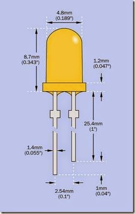
When an LED indicator is described as being through hole, it has leads for insertion into holes in a circuit board. The term does not mean that the indicator itself is meant to be pushed through a hole in a panel, although this may also be done. The LED is cylindrical with a hemispherical top that acts as a lens. The leads are relatively thick, to conduct heat away from the component. A dimensioned diagram of a typical LED measuring 5mm in diameter is shown in Figure 22-1.
clip_image005

Figure 22-1. Dimensions of a typical 5mm LED. The longer wire connects with the anode, while the shorter wire connects with the cathode. Adapted from a data- sheet published by Lite-On Technology Corporation.

An LED indicator that is not the through-hole type is usually a surface-mount component. LEDs for surface mounting are mostly rectangular and can be as small as 1mm x 0.5mm. They may require a heat sink.

Schematic Symbols

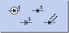
Figure 22-2 shows a variety of symbols that are commonly used to represent an LED. The triangle at the center of each symbol points in the direction of conventional (positive-to-negative) cur- rent flow—from the anode to the cathode. Each pair of arrows radiating away from the diode indicates emitted light. Wavy arrows are some- times used to represent infrared (thermal) radiation. Often, however, an infrared LED is represented in exactly the same style as an LED that emits visible light. With the exception of the wavy arrows, the various styles of schematic symbol are functionally identical and do not identify different attributes of the component such as size or color.
clip_image007

Figure 22-2. Various symbols may be used to represent an LED. See text for details.

Common Usage

LED indicators have mostly displaced neon bulbs and miniature incandescent lamps for the purpose of showing the status of a device. They are found in industrial control panels, home audio systems, battery chargers, washer/dryers, and many other consumer-electronics products. Higher output variants are used in flashlights, traffic signals, taillights on automobiles, and for illumination of subjects that are being photo- graphed. LED indicators may be assembled in large numbers in attention-getting displays such as Christmas lights.

Red, orange, yellow, green, and blue are the basic standard colors. LEDs that appear to generate white light are common, but they do not emit an evenly weighted spectrum of wavelengths. See “Non-Incandescent Sources” on page 174 for a discussion of this topic.

How It Works

An LED, like any diode, contains a semiconductor PN junction that conducts current only in the forward direction (i.e., from the more-positive side of a power supply to the more-negative side). The diode becomes conductive above a threshold voltage sufficient to force electrons in the n-type region and holes in the p-type region to combine with each other. Each time this oc- curs, energy is released. The energy liberated by one electron-hole combination creates a pho- ton, or one quantum of light.

The amount of energy released depends on the band gap, which is a property of the semiconductor material. The band gap is the smallest energy that can create an electron-hole pair. The energy determines the light’s wavelength, and thus the color.

The band gap also determines the threshold voltage of the LED. For this reason, LEDs of different colors have widely different threshold voltages.

Because an LED will often be used in devices where the DC power supply exceeds the maxi- mum forward voltage, a series resistor is customarily used as a simple way to restrict current through the diode.

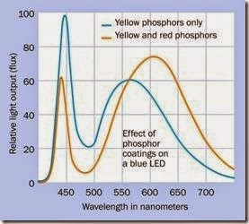
The light emitted by a colored LED indicator tends to include only a narrow range of wave- lengths. However, the addition of a phosphor coating to the diode can broaden the output. This technique is used to make the light from a blue LED appear white, as shown in Figure 22-3. Most white LEDs are actually blue LEDs with a colored phosphor layer added. See the section

on LED area lighting in Chapter 23 for a more detailed discussion of this topic.
clip_image010

Figure 22-3. Increasing the range of emitted wavelengths by adding phosphors to a blue LED. Source: Philips Gard- co Lighting.

Multicolor LEDs and Color Mixing

If red, green, and blue light sources are mounted extremely close together, the eye perceives them as a single source, of a color determined by their combined relative intensities. This system of additive color mixing is shown in Figure 17-14 in the entry dealing with LCDs. It is used in LED indicators that contain red, green, and blue light- emitting diodes in a single epoxy or silicone capsule.

While most video monitors use white LEDs or fluorescent lights to form a backlight for an LCD video screen, some high-end monitors use a matrix of very tiny red, green, and blue LEDs, because the combination of these separate col- ors generates a wider gamut of color wave- lengths. The concept of gamut is discussed in “Color” in the LCD entry. The tiny LEDs in a back- light cannot be considered as indicators, but in- dicators are used for this purpose in billboard- sized video displays.

Variants

LED indicators vary widely in size, shape, intensity, view angle, diffusion of light, wavelength of light, minimum and maximum forward voltage, and minimum and maximum forward current.

Size and Shape

The original sizes for round LED indicators were 3mm, 5mm, or (more rarely) 10mm in diameter. Today, through-hole LEDs are sold in many inter- mediate sizes, although 3mm and 5mm are still most widely used.

The traditional round LED indicator is now augmented with square and rectangular shapes. In a parts catalog, a pair of dimensions such as 1mm × 5mm suggests that the LED is rectangular.

Intensity

The light intensity of an LED is usually expressed in millicandelas, abbreviated mcd. There are 1,000 mcd in a candela. For more information about units for measurement of light, see “Inten- sity” on page 178.

The candela measures the luminous flux, or visible radiant power, contained within a specified angle of dispersion, usually referred to as the view angle. This can be imagined as the rotated angle at the apex of a cone, where the cone de- fines the “spread” of the light, and the source is at the apex.

If a diode is emitting a fixed amount of luminous flux, the rating in mcd will increase with the in- verse square of the view angle. This is because the light delivered to an area in front of the LED will become more intense as the angle becomes smaller. The use of mcd to rate the brightness of an LED can be misleading if it is not considered in comparison with the view angle.

For example, suppose an LED is rated at 1,000 mcd and has a view angle of 20 degrees. Now suppose the same diode is embedded in a different epoxy or silicone capsule with a lens that creates a view angle of only 10 degrees. The LED

will now be rated at 4,000 mcd, even though its total power output is unchanged.

• To compare the brightness of two LED indicators meaningfully, they should share the same view angle.

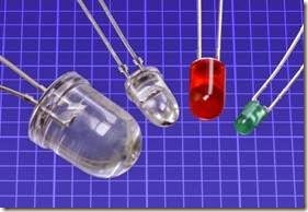
Four through-hole LED indicators with a wide range of specifications are shown in Figure 22-4. From left to right: water-clear white generic, 10mm; Vishay TLCR5800 5mm (emitting red, even though the capsule is water-clear), rated for 35,000mcd with 4 degrees view angle; Everlight HLMPK150 5mm red diffused, rated for 2mcd with 60 degrees view angle; and Chicago 4302F5-5V 3mm green, rated for 8mcd at 60 de- grees view angle, containing its own series resistor to allow direct connection with a 5VDC power supply.
clip_image013

Figure 22-4. Four assorted LED indicators with very different specifications. See text for details.

Efficacy

The radiant luminous efficacy (LER) of an incandescent light source compares how effective it is at channeling its output within the visible spectrum, instead of wasting it in other wavelengths, especially infrared. Note that the word efficacy has a different meaning from efficiency. The LER acronym may help to avoid confusion.

LER is expressed in lumens per watt, and in an incandescent bulb it is calculated by dividing the power emitted in the visible spectrum (the luminous flux) by the power emitted over all wave- lengths. This is described in detail on “Efficacy” on page 179 in the entry dealing with incandescent lamps.

In an LED indicator, almost all the radiation can be within the visible spectrum, but some power is wasted by generating heat internally. The efficacy varies depending on the type of LED; thus a red-orange indicator can have an efficacy of 98% while a blue LED will be probably below 40%.

Diffusion

Some LED indicators use epoxy or silicone that is formulated to be translucent or “cloudy” instead of transparent. They diffuse the light so that it is not projected in a defined beam, has a softer look, and has an approximately equal intensity when viewed from a wider range of angles.

“Clear” and “diffused” are options that must be taken into account when choosing LEDs from an online catalog, unless the user is willing to turn a clear LED into a diffuse LED by applying some sandpaper.

Wavelength and Color Temperature The wavelength of light is measured in nanometers (abbreviated nm), a nanometer being 1 billionth of a meter. The visible spectrum extends

from approximately 380nm to 740nm. Longer wavelengths are at the red end of the spectrum, while shorter wavelengths are at the blue end.

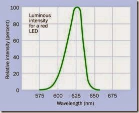
A typical LED emits a very narrow range of wave- lengths. For example, Figure 22-5 shows the emission from a standard red LED indicator manufactured by Lite-On. Graphs of this type are typically included in manufacturers’ datasheets.

Because a red LED stimulates the cones in the eye that respond to red light, it “looks red” even though the color is not comparable with the natural red that is seen, for instance, in a sunset. That natural color actually contains an additional spread of wavelengths.
clip_image015

Figure 22-5. The narrow range of wavelengths emitted by a typical red LED indicator.

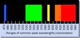
The following list shows the ranges of peak out- put values, in nanometers, for the most commonly available basic LED indicators (LEDs that emit other wavelengths are available, but they are less common):

• Infrared LED: 850 to 950

• Red LED: 621 to 700

• Orange LED: 605 to 620

• Amber LED: 590 to 591

• Yellow LED: 585 to 590

• Green LED: 527 to 570

• Blue LED: 470 to 475

• Ultraviolet LED: 385 to 405

Figure 22-6 shows this list graphically, omitting infrared and ultraviolet LEDs.

For almost 30 years, blue LEDs were a laboratory curiosity of little practical value, as efficiencies were stuck around 0.03%. An efficiency of more than 10% was finally achieved in 1995. Blue LEDs were marketed soon afterward.

However, when yellow phosphors are added to create the impression of white light by spreading the output over the whole visible spectrum, the wavelengths around 500nm are still not well rep- resented, as suggested in Figure 22-3.
clip_image017

Figure 22-6. Ranges for peak wavelengths of the most commonly used LEDs. (Source: Survey of approximately 6,000 through-hole LEDs stocked at www.mouser.com.)

Fluorescent lights perform even more poorly than white LEDs, as can be seen in Figure 18-4 in the entry describing incandescent lamps.

Because white LEDs do not emit a single peak of wavelengths, their color is expressed in color temperature rather than nanometers. The concept of color temperature is explained in “Spectrum” on page 173. White LEDs are available rated from 2,800 to 9,000 degrees Kelvin, and are discussed in more detail in the LED area lighting entry in this encyclopedia.

Internal Resistor

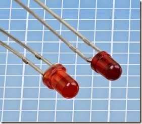
To eliminate the chore of adding a series resistor to limit current through an LED, some indicators are sold with a series resistor built in. They may be rated for use with 5VDC or 12VDC, but are externally indistinguishable from each other. They are also externally indistinguishable from LEDs that do not contain series resistors. Figure 22-7 shows two 3mm LEDs, the one on the right containing its own series resistor, the one on the left being a generic LED without a series resistor.

Because of the nonlinear response of a diode, LEDs with or without internal resistors cannot be distinguished from each other reliably with a multimeter. If the meter is set to measure ohms, typically it will give an “out of range” error to all types of LED. If it is set to identify a diode, the reading will not tell you if the LED contains a resistor.
clip_image019

Figure 22-7. An LED (left) that does not contain its own series resistor is usually indistinguishable from one that does (right).

One way to determine whether an LED contains an internal series resistor would be to connect it with a variable power supply through a multi- meter set to measure mA. Carefully increase the supply voltage from zero until the meter shows a current of 20mA. If the LED does not contain a series resistor, the supply voltage will be close to the recommended forward voltage for that type of LED (no lower than 1.6V for a red LED, and no higher than 3.6V for a white LED). If the LED does contain a series resistor, the supply voltage will be higher. This procedure is time consuming, but may be worthwhile to evaluate multiple LEDs that are known to be identical.

Multicolored

The leads for an LED indicator containing two or more diodes can be configured in several ways:

• Two leads, two colors. Two diodes are mounted internally in parallel, but with opposite polarity.

• Three leads, two colors. Two diodes share a common anode or common cathode.

• Four leads, three colors (RGB). Three diodes share a common anode or common cathode.

• Six leads, three colors. Three diodes, each with its own pair of leads, separate from the others.

Infrared

Most infrared emitters are LEDs that generate wavelengths longer than 800nm. They are found in handheld remotes to control consumer- electronics devices such as televisions and stereo systems, and are also used in some security systems, although passive infrared motion detectors, which assess infrared radiation from sources such as people or vehicles, are more commonly used for this purpose.

In conjunction with an infrared emitter, an infra- red sensor is necessary, and must be sensitive to the same wavelength. To prevent false positives, the emitter modulates its output, typically with a carrier frequency between 10 and 100kHz. Remotes often use carrier frequencies of 30 to 56kHz. At the receiving end, the signal is processed with a band-pass filter matching the modulation frequency. Many different pulse-coding schemes are used, and no particular standard is dominant.

Ultraviolet

Because ultraviolet radiation can damage the eyes, LED indicators that emit ultraviolet light are potentially dangerous and should be used with caution. A yellow eyeshield can be worn to block the short wavelengths.

Ultraviolet light can be used to cure some adhesives and dental filling material. It can also kill bacteria, and can detect fluorescent print on bank notes, to check for counterfeiting. Ultraviolet flashlights are sold to detect some species of pests, such as scorpions, which fluoresce in re-sponse to ultraviolet light.

Values

The specification for an LED will include the wavelength of emitted light, luminous intensity, maximum forward voltage and current, maximum reverse voltage and current, and working values for voltage and current. All these values are important when choosing an indicator for a specific function.

White LEDs for room lighting or external use are calibrated differently. See the entry for LED area lighting in Chapter 23.

Forward Current

About half of all the thousands of available types of LED indicators are rated for a typical forward current of 20mA to 25mA. Absolute maximum ratings may be twice as high, but should not generally be applied.

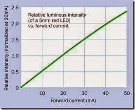
The light intensity of a typical 5mm red LED indicator is plotted against its forward current in Figure 22-8. Note that current and light intensity have an approximately linear relationship up to the typical working current of 20mA. Even above this point, to the absolute maximum of 50mA, the light intensity rolls off only a very small amount.

Although an LED indicator can be dimmed by controlling the current passing through it, the current does not have a linear relationship with the applied voltage, and the indicator will stop functioning completely when the voltage drops below the threshold required by the diode. Consequently, LEDs are commonly dimmed by using pulse-width modulation.

Because of the nonlinear response of a diode, LEDs with or without internal resistors cannot be distinguished from each other reliably with a multimeter. If the meter is set to measure ohms, typically it will give an “out of range” error to all types of LED. If it is set to identify a diode, the reading will not tell you if the LED contains a resistor.

Low-Current LEDs

Indicators that require a very low forward current are convenient for direct connection to output pins of logic chips and other integrated circuits. Although a single output from an HC family chip is capable of supplying 20mA without damaging the chip, the current will pull down the output voltage, so that it cannot be used reliably as an input to another chip while also lighting the LED.
clip_image021

Figure 22-8. The relationship between forward current and light intensity of a typical 5mm LED indicator is approximately linear up to the 20mA operating current, and almost linear up to the absolute maximum of 50mA.

Various LED indicators drawing 2mA or 1mA are available, with intensities typically ranging be- tween 1.5mcd and 2.5mcd. This low light output is still bright enough for viewing in a lab-bench environment. Low-current blue LEDs are not available. The only LEDs that draw as little as 1mA are red, as this is the most efficient type.

Using a higher value series resistor with a generic LED will of course reduce its current consumption, and some light will be visible so long as the forward voltage across the LED remains at its minimum level or above.

Forward Voltage

Red is the color that requires not only the least forward current, but the lowest forward voltage. In the range of 1.6VDC to 1.7VDC, all the LEDs are red. Typical forward voltages for various colors are shown here:

• Infrared LED: 1.6V to 2V

• Red LED: 1.6V to 2.1V

• Orange LED: 1.9V to 2.1V

• Amber LED: 2V to 2.1V

• Yellow LED: 2V to 2.4V

• Green LED: 2.4V to 3.4V

• Blue LED: 3.2V to 3.4V

• Ultraviolet LED: 3.3V to 3.7V

• White LED: 3.2V to 3.6V

Color Rendering Index

The color rendering index (CRI) evaluates the fidelity with which a light source is capable of dis- playing the full visible spectrum. It ranges from a perfect score of 100 down to 0 or even lower (sodium-vapor street lighting has a negative value). Computing the index requires standard reference color samples and has been criticized for generating scores that do not correlate well with subjective assessments.

Incandescent bulbs can have a CRI of 100, while an uncorrected white LED may score as low as 80.

Life Expectancy

Because the light output from an LED tends to decrease very gradually with time, the life expectancy is often defined as the number of hours required for the output to diminish to 70% of its output when new. Life expectancy is commonly stated on datasheets for high-brightness white LEDs, but is often omitted from datasheets for LED indicators.

Unlike incandescent lamps and fluorescent lights, LEDs do not have a shorter lifespan if they are frequently cycled on and off.

Light Output and Heat

The light intensity of an LED, measured in mcd, can vary from a few mcd to a maximum of 40,000mcd. Intensities above 30,000mcd generally are achieved by limiting the view angle to 15 degrees or less. Because the candela is weighted toward the central, green segment of the visible spectrum, green LEDs are likely to have a relatively high mcd rating. LEDs rated between 20,000mcd and 30,000mcd, with a view angle of 30 degrees, are almost all green.

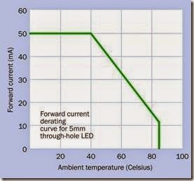
Datasheets may often include a derating curve showing the lower limit that should be placed on forward current through an LED indicator when its temperature increases. In Figure 22-9, the LED should be operated only within the boundary established by the green line.
clip_image023

Figure 22-9. Safe operation of an LED entails limiting the forward current if the temperature increases. The green line shows the boundary for operation of this particular component.

View Angle

An LED formed from transparent epoxy or silicone (either water-clear or tinted) will create a well-defined beam with a view angle as narrow as 4 degrees or as wide as 160 degrees (in a few instances). The most common view angles for LED indicators are 30 degrees and 60 degrees.

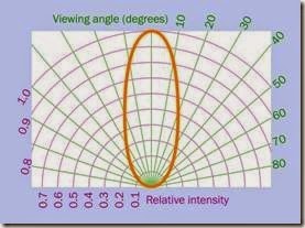
Datasheets for LED indicators often include a spatial distribution graph showing the relative intensity of the light when viewed at various angles from the axis of the LED. The spatial distribution graph in Figure 22-10 is for an LED with a view angle defined as 40 degrees. This is the angle at which the relative luminous intensity diminishes to 50%.
clip_image025

Figure 22-10. A spatial distribution graph shows the rela- tive intensity of light from an LED at various view angles.

The view angle is of special concern in devices such as flashlights, where the spread of the beam affects the functionality.

How to Use It

Like all semiconductor devices, LEDs can be impaired by excess forward current and may break down irreversibly if subjected to excess reverse voltage. Their limits for reverse voltage are much lower than those of a rectifier diode. They are also vulnerable to heat, but are not particularly vulnerable to static electricity.

Polarity

A through-hole LED will have two leads of un- equal length. The longer lead connects internally with the anode of the diode, and should be wired externally to the “more positive” side of a power source. The shorter lead connects internally with the cathode of the diode, and should be wired externally to the “more negative” side of a power source.

To remember the functions of the leads, consider that the plus sign would be twice as long as a minus sign if its horizontal and vertical stroke were disassembled and placed end to end.

If a round LED has a flange around its base, a flat spot in the flange will be closest to the cathode side of the component.

Series Resistor Value

Because the effective internal resistance of a di- ode is not a constant value at different voltages, a trial-and-error approach may be necessary to determine the ideal value for a series resistor with an LED indicator. For this purpose, a trimmer potentiometer can be used with a sample LED while measuring the current through it and the voltage drop across it. A fixed-value resistor can then be substituted. If the choice is between a resistor value that is a little too high and a value that is a little too low, the higher value resistor should be used.

An approximate value can be found using a very simple formula in which R is the resistor value, VCC is the supply voltage, VF is the forward volt- age specified for the LED, and I is the desired cur- rent:

R = (VCC – VF) / I

Normally a series resistor rated at 1/4 watt will be acceptable, and 1/8 watt may be used in 5VDC circuits. However, care should be taken with a power supply of 9V or higher. Suppose an LED is rated for 1.8V forward voltage at 20mA. In a 5V circuit, the voltage drop across the series resistor will be:

V = 5 – 1.8 = 3.2

Therefore, the resistor must dissipate 3.2V * 20mA = 64mW. This is comfortably below the 125mW rating of a 1/8 watt resistor. However, with a 9V power supply, the voltage drop across the series resistor will be:

V = 9 – 1.8 = 7.2

Now the resistor must dissipate 7.2V * 20mA = 144mW. This exceeds the 125mW limit for a 1/8 watt resistor.

LEDs in Parallel

If multiple LEDs are to be driven in parallel, and none of them has to be switched individually, it is naturally tempting to save time by using a single series resistor for all of them. In these circumstances, assess the maximum current carefully and multiply by the voltage drop imposed by each of the LEDs, to determine the wattage of a series resistor.

Linking dissimilar LEDs in parallel is not recommended, because the threshold voltage decreases with increasing temperature. The hottest LED will therefore receive the largest current, and thus become even hotter. Thermal runaway can result.

LEDs containing their own series resistors can safely be wired in parallel.

Multiple Series LEDs

A series resistor wastes current by dissipating it as heat. In an application where two or more LED indicators will be illuminated simultaneously, the LEDs can be connected in series with a lower- value resistor, and three LEDs in series may elim- inate the need for a resistor completely, depending on the voltage of the power supply. Here again a trimmer potentiometer should be used to determine an ideal value for any series resistor that may be necessary.

Comparisons with Other Light Emitters

Because LED indicators have largely replaced ne- on bulbs and miniature incandescent lamps, comparisons are of limited importance at this point. The situation regarding LED area lighting is different in that it is still competing actively with fluorescent lights and, in some instances, halogen. A list of advantages and disadvantages for high-intensity white LEDs is given in “Com- parisons” on page 223. The advantages of incan- descent lamps are listed in “Relative Advantag- es” on page 179.

Other Applications

LEDs are used in optocouplers and in solid- state relays. Usually an infrared LED is embedded inside a chip or a plastic module, and emits light through an interior channel to activate a phototransistor. This arrangement provides electrical isolation between the switching signal and the switched current.

Some sensors use an LED paired with a photo- transistor at opposite sides of a U-shaped plastic mount. A sensor of this type can monitor industrial processes or may be found inside a photo- copy machine, to detect the presence of a sheet of paper.

What Can Go Wrong

voltage of the diode. The exception to this rule is if the internal resistance of the battery is high enough to limit the current, as in the case of button-cell batteries.

Storage Issues

LEDs of different types are often indistinguishable from each other. They can also be indistinguishable from photodiodes and phototransistors. Careful storage is mandatory, and reusing LEDs that have been breadboarded may cause future problems if they are wrongly identified.

Polarity

If the leads on an LED indicator are trimmed, and if the indicator lacks a flange in which a flat spot will identify the cathode, the component is easily misused with reversed polarity. If it is connected

Excessive Forward Voltage

Like any diode, the LED has a threshold voltage in the forward direction. If this threshold is exceeded, the effective internal resistance of the LED falls very rapidly. Current rises equally rapidly, and quickly damages the component, unless it is protected by an appropriate series resistor.

Excessive Current and Heat Exceeding the recommended value for forward current, or allowing an LED to overheat, will shorten its lifetime and cause a premature dimming of light output. LEDs generally require some current limiting or regulation (most commonly with a series resistor). They should not be connected directly to a voltage source such as a battery, even if the battery voltage matches the with a component that has limited current sourcing capability (for instance, the output pin of a digital chip), the LED will probably survive this treatment. However, maximum reverse voltage is often as low as 5VDC. To minimize the risk of errors, the anode lead can be left slightly longer than the cathode lead when they are trimmed for insertion in a breadboard or perforated board.

Internal Resistors

As previously noted, it is difficult to distinguish an LED that contains its own series resistor from another LED that does not. The two types should be stored separately, and should be reused circumspectly.


laser:What It Does,How It Works,Laser Diode,Coherent Light,Variants,CO2 Lasers,Fiber Lasers,Common Applications,What Can Go Wrong,Risk of Injury,Inadequate Heat Sink,Uncontrolled Power Supply and Polarity.

laser

The term maser was coined in the 1950s to describe a device that used stimulated emission to amplify microwaves. When a device using similar principles amplified visible light in 1960, it was termed an optical maser. However, that term is now obsolete, having been replaced with laser. This term is always printed in lowercase letters, even though it is an acronym for Light Amplification by Stimulated Emission of Radiation.

The invented verb to lase is derived from laser and is used to describe the process of generating laser light, with the past participle lased and present participle lasing some- times being used.

Thousands of laser variants exist. Because of space limitations, this entry will concentrate primarily on laser diodes, which are the smallest, most common, and most affordable type.

What It Does

A laser generally emits a thin beam of intense light, often in the visible spectrum, and usually in such a narrow range of wavelengths, it can be considered monochromatic. The light is also coherent, as explained below.

Light output from a laser has three important at- tributes:

• Intensity. A high-powered laser can deliver energy to a very small, well-defined area, where it may be capable of burning, cutting, welding, or drilling. Large lasers may also be used as weapons, or for power transmission.

• Collimation. This term describes a beam of light that has parallel boundaries, and there- fore does not disperse significantly when passing through a transparent medium such as air, glass, or a vacuum. A laser beam can have such excellent collimation, it can be used in precision measuring devices, and has been transmitted over very long distances, even from the Earth to the Moon, where astronauts placed reflectors during the Apollo missions.

• Controllability. Because the beam can be generated with eletrical power, its intensity can be modulated rapidly with relatively simple electronic circuits, enabling applications such as burning microscopic pits in the plastic of a CD-ROM or DVD.

Laser diodes are now more common than all other forms of lasers. They are found in pointers, printers, barcode readers, scanners, computer mice, fiber-optic communications, surveying tools, weapon sights, and directional lighting sources. They are also used as a light source to trigger more powerful lasers.

No generic symbol is used for a laser, but a laser diode is often represented with the same symbol that is used for a light-emitting diode. See Figure 22-2 in the entry for LED indicators.

How It Works

A laser is built around a gain medium, which is a material that can amplify light. The medium can be a solid, liquid, gas, or plasma, depending on the type of laser.

Initially, an input of energy provides stimulation for some atoms in the gain medium. This is known as pumping the laser. The energy input can come from a powerful external light source, or from an electric current.

Stimulation of an atom raises the quantum energy level of an electron associated with the atom. When the electron collapses back to its former energy state, it releases a photon. This is known as spontaneous emission.

If one of the photons encounters an atom that has just been excited by the external energy source, the atom may release two photons. This is known as stimulated emission. Beyond a thresh- old level, the number of released photons can increase at an exponential rate.

If two parallel reflectors are mounted at opposite ends of the gain medium, they form a resonant cavity. Light bounces to and fro between the reflectors, while pumping and stimulated emission amplifies the light during each pass. If one of the mirrors is partially transparent, some of the light will escape through it in the form of a laser beam. The partially transparent mirror is known as the output coupler.

Laser Diode

A laser diode contains an LED. (See “How It Works” on page 207 for a more detailed description of the function of an LED.) The p-n junction of the diode functions as the resonant cavity of the la- ser. Forward bias injects charges into the junction, causing spontaneous emission of photons. The photons, in turn, cause other electrons and electron-holes to combine, creating more photons in the process of stimulated emission. When this process crosses a threshold level, current passing through the diode causes it to lase.

The original patent for a laser diode was filed by Robert N. Hall of General Electric in 1962, and the diagram in Figure 21-1 is derived from the draw- ing in that patent, with color added for clarity.

clip_image006

Figure 21-1. The original design for a laser diode, from the patent filed in 1962.

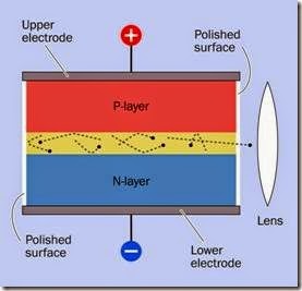
In the figure, the junction shown as a yellow layer forms the resonant cavity in which lasing occurs. It measures only 0.1 microns thick (the diagram is not drawn to scale). Its vertical front side is highly polished, and is parallel to the back side, which is also highly polished. Thus, photons reflect between these two vertical sides. The slan- ted face visible in the figure, and the other slanted face opposite it, are oriented and roughened to minimize internal reflection between them.

Figure 21-2 shows a simplified cross-section of the laser diode.

clip_image008

Figure 21-2. Simplified cross-section of a laser diode.

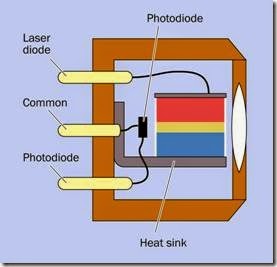
Figure 21-3 shows a cross-section of the diode installed in a component sold as a laser. It in- cludes a photodiode to sense the intensity of light emerging through the polished rear end of the laser diode. External electronics are necessa- ry to control the intensity of the laser, using feed- back from the photodiode.

The component has three pins (shown pale yel- low in the figure), one connecting to the photo- diode, another connecting to the p-type layer of the laser diode, and the third being common to the n-type layer of the laser diode and the ground side of the photodiode.

A photograph of a laser diode is shown in Figure 21-4. Note the three pins, comparable to the pins shown in Figure 21-3, indicating that this component requires external control electronics.

In Figure 21-5, a laser is shown with a surface- mount chip adjacent to the solder pad connect- ing the blue wire. The presence of this chip, with only two wires, indicates that this component has its own control electronics and requires only a DC power supply.

clip_image010

Figure 21-3. A laser diode is typically mounted with a photodiode to provide feedback for a driver circuit, to control the current consumed by the laser.

clip_image012

Figure 21-4. Lite-On 505T laser diode that emits light at 650nm. Power consumption 5mW at 2.6VDC. As indicated by the graph squares, this component is only about 0.2” in diameter.

clip_image014

Figure 21-5. This laser incorporates its own control electronics and requires only a 5VDC power supply. It draws 30mA and generates an output up to 5mW.

Coherent Light

The emission of coherent light by a laser is often explained by suggesting that wavelengths are synchronized with each other. In fact, there are two forms of coherence that can be described approximately as spatial coherence and wave- length coherence.

If an observer looks up at a cloudy sky, the eye will perceive light radiating chaotically from many distances and directions. Thus, the light is not spatially coherent. The light also consists of many wavelengths, and thus it is not wavelength-coherent.

The filament of an incandescent lamp is a much smaller source of light, but still large enough to generate a profusion of light emissions that are spatially incoherent. The light also includes many different wavelengths.

Suppose a barrier containing a very tiny hole is placed in front of the incandescent lamp. If the aperture is very small, an observer on the far side will see the light as a point source. Consequently, the light that emerges from it is now spatially coherent, and will not have chaotically overlapping waves. If the light then passes through a filter, its wavelengths also will become coherent. This is suggested in Figure 21-6 where the light source is an incandescent lamp emitting a wide range of wavelengths.

clip_image016

Figure 21-6. An incandescent lamp, at the bottom of the figure, emits incoherent light at many wavelengths (exaggerated here for clarity). When it passes through a pin- hole, it becomes spatially coherent. When it then passes through a colored filter, it becomes wavelength coherent.

The small amount of light emerging through a pinhole is inevitably much dimmer than light from the original source. A laser, however, amplifies its light output, as well as tending to be- have like a point source. The “hall of mirrors” effect of the parallel reflective surfaces in the resonant cavity causes much of the light to shuttle to and fro over a long distance before it emerges through the output coupler. Any light that deviates significantly from the axis of the laser will not escape at all, because the deviations will be cumulative with each reflection. Thus, the light from a laser appears to come from a point source at an almost infinite distance.

Because of the particular geometry of a light- emitting diode, the output from a laser diode is not naturally collimated, and tends to spread by an angle of around 20 degrees. A lens must be used to focus the beam.

Variants

Values

The output power of a laser is measured in watts (or milliwatts). This should not be confused with the power consumed by the device.

In the United States, any device sold as a laser pointer is limited to a power output of 5mW.

Lasers are sold generally as fully assembled tools for a specific purpose. A very brief summary of CO2, fiber, and crystal lasers is included here.

CO2 Lasers

The gain medium is primarily carbon dioxide but also contains helium and nitrogen, with some- times hydrogen, water vapor, and/or xenon. The laser is electrically pumped, causing a gas dis- charge. Nitrogen molecules are excited by the discharge and transfer their energy to the CO2 molecules when colliding with them. Helium helps to return the nitrogen to base energy state and transfer heat from the gas mixture.

CO2 lasers are infrared, and are commonly used in surgical procedures, including ophthalmology. Higher powered versions have industrial applications in cutting a very wide range of materials.

Fiber Lasers

Light is pumped via diodes and amplified in purpose-built glass fibers. The resulting beam has a very small diameter, providing a greater intensity than CO2 lasers. It can be used for metal engraving and annealing, and also for working with plastics.

Crystal Lasers

Like fiber lasers, they are pumped by diodes. These compact lasers are available in a very wide variety of wavelengths, covering the whole visible spectrum, infrared, and ultraviolet. They find applications in holography, biomedicine, interferometry, semiconductor inspection, and material processing.

However, laser diodes packaged similarly to laser pointers can be mail-ordered with an output of 200mW or more. The legal status of these lasers may be affected by regulations that vary state by state.

In a CD-RW drive that is capable of burning a disc, the diode may have a power of around 30mW. A laser mounted in a CD-ROM assembly is shown in Figure 21-7.

clip_image019

Figure 21-7. An assembly incorporating a laser for reading a CD-ROM.

Lasers have such a narrow range of wavelengths, they are given specific output values in nanometers. A laser in an optical mouse may have a wavelength of 848nm; in a CD drive, 785nm; in a

bar-code reader, 670nm; in a modern laser pointer, 640nm; in a Bluray disc player, 405nm.

How to Use It

While powerful lasers in a laboratory setting have exotic applications, a typical low-power laser di- ode has become so affordable (costing less than $5 in some instances, at the time of writing) it can be considered merely as a useful source of a clearly defined light beam, ideal for detecting the position of a movable mechanical component or the presence of an intruder.

Generic light-emitting diodes are made with a view angle (i.e., a dispersion angle) as low as 3 degrees, but the beam is soft-edged compared with the precise boundary of a laser beam, and cannot be used reliably in conjunction with sensors at a distance of more than a few inches.

Laser diodes that are sold as components may or may not have current-limiting control electronics built in. Applying power to the laser diode directly will result in thermal runaway and rapid destruction of the component. Drivers for laser diodes are available separately as small, preassembled circuits on breakout boards.

For many applications, it may be simpler and cheaper to buy a laser diode as an off-the-shelf product. A laser pointer provides an easy way to get a source of laser light, and if it would normally be driven by two 1.5V batteries, it can be adapted to run off a 5V supply by using a 3.3V voltage regulator.

Common Applications

In addition to being used with PowerPoint presentations and in conjunction with position sensors, laser pointers have other applications:

• Astronomy. A high-powered laser beam is visible even in clear air as a result of interaction with air molecules. This is known as Rayleigh scattering. The phenomenon allows one person to point out a star (or planet) for another person. Because celestial objects are

so far away, parallax error is not detectable by two people viewing the beam while standing next to each other. A laser pointer may also be mounted on a telescope to assist in aiming the telescope at an object of inter- est. This is easier than searching for an object through an eyepiece.

• Target acquisition. Lasers are commonly used on firearms to assist in targeting, especially in low-light conditions. Infrared lasers can be used in conjunction with infrared viewing goggles.

• Survival. A small laser can be included in emergency supplies to signal search teams. A laser can also be used to repel predatory animals.

What Can Go Wrong
Risk of Injury

Lasers are potentially dangerous. Those that have an infrared or ultraviolet output are more dangerous than those with a visible beam, as there is no visual warning that the laser is active. A laser is capable of scarring the retina, although controversy exists regarding the power output that should be considered a high risk.

If a project incorporates a laser, it should be switched off while building or testing the device. It may be advisable to wear protective glasses that block laser light even when an experimenter feels confident that a laser is switched off.

Active lasers should never be pointed at people, vehicles, animals (other than dangerous animals), or oneself.

Inadequate Heat Sink

Lasers may be designed and rated for intermit- tent use. The burner assembly for a CD-ROM drive, for instance, will be rated for pulsed power, not continuous power. Read datasheets carefully, and provide an adequate heat sink.

Uncontrolled Power Supply

A diode laser that does not have a feedback sys- tem in place to control the flow of current can self-destruct.

Polarity

Both the light-emitting diode and the photo- diode in a three-pin laser package can be damaged by incorrect polarity of applied power. Pin functions should be checked carefully against datasheets.


fluorescent light:What It Does,How It Works,Ballast and Starter,Flicker,Variants,CCFLs,Sizes,Comparisons,Values,Brightness,Spectrum,Cannot Dim,Burned Out Electrodes and Ultraviolet Hazard.

luorescent light

This entry deals primarily with fluorescent tubes (infrequently but sometimes described as fluorescent lamps), and compact fluorescent lamps (CFLs) that are marketed as a substitute for incandescent lamps. Cold-cathode fluorescent lamps (CCFLs) are also mentioned.

Vacuum fluorescent devices have a separate entry in this encyclopedia. A fluorescent tube or CFL does not contain a vacuum.

Although the diode(s) in a white LED area lighting unit are coated with a layer of fluorescent phosphors, they are not categorized here as fluorescent lights, and have their own entry.

A neon bulb resembles a fluorescent light in that it is a gas-discharge device, but the interior of its glass envelope is usually not coated with fluorescent phosphors, and there- fore it has its own entry.

What It Does

Fluorescent tubes or compact fluorescent lamps (CFLs) are primarily used for area lighting. A partially disassembled CFL appears in Figure 20-1, showing the control electronics that are normally hidden inside the base.

There is no standardized schematic symbol to represent a fluorescent light. Figure 20-2 shows three commonly used symbols for a fluorescent tube on the left, and three symbols for a CFL on the right. Note that two of the symbols for a CFL are the same as those for an incandescent lamp, shown in Figure 18-1.

How It Works

Luminescence is the emission of light as a result of a process that does not require heat. (The op- posite phenomenon is incandescence, in which heating causes an object to emit light; see Chapter 18 for a description of incandescent lamps.)

Fluorescence is a form of luminescence. It occurs when electrons in a material are energized and then make a transition back to ground level, at which point they radiate their energy as visible light. The incoming energy can consist of other light at a higher frequency. Some creatures, including species of arachnids and fish, will fluoresce when they are lit with ultraviolet light.

clip_image006

Figure 20-1. A compact fluorescent lamp with its base cut away to reveal the control electronics.

clip_image008

Figure 20-2. Schematic symbols to represent fluorescent tubes and bulbs are not standardized. See text for details.

A fluorescent tube or lamp contains a very small amount of mercury vapor that can be stimulated to emit ultraviolet light. This encounters a thin layer of phosphors coating the inner surface of the glass enclosure. The light causes the phosphors to fluoresce, emitting a diffuse radiance in the visible spectrum.

The tube or lamp also contains one or more inert gases such as argon, xenon, neon, or krypton at about 0.3% of normal atmospheric pressure. Two electrodes inside the glass enclosure are made primarily from tungsten, which can be preheated to initiate ionization of the gas. Confusingly, both electrodes are often referred to as cathodes.

The function of the gas is not to emit light, but to conduct electric current, so that free electrons may encounter mercury atoms, raising their electrons briefly to a higher energy level. When one of these electrons reverts from its unstable energized state to its previous energy level, it emits a photon at an ultraviolet wavelength.

Figure 20-3 provides a diagram showing the interior of a fluorescent tube.

clip_image010

Figure 20-3. The basic parts of a fluorescent tube.

Ballast and Starter

Heating the tungsten electrodes is necessary but not sufficient to trigger ionization. A high- voltage pulse is also needed when the light is switched on. In a typical 48” tube, the pulse may range from 200V to 300V.

After current flow has been established, the gas, which is now a plasma, enters a phase of negative resistance. Current passing through it will tend to increase even if the voltage decreases. This process must be controlled to prevent the formation of an arc, which will destroy the electro- des. (A similar process occurs in any gas dis- charge tube, such as a neon bulb, and is de- scribed in a graph in Figure 19-5.)

To heat the electrodes, ionize the gas, and then control the current, the fixture for a fluorescent tube contains components that are separate from the tube. In their simplest, traditional form, these components consist of a starter and a ballast. The starter is a neon bulb that contains a bimetallic strip serving as a normally closed switch. It allows current to flow through the electrodes in series, to heat them. The basic circuit is shown in Figure 20-4.

clip_image012

Figure 20-4. The traditional circuit to trigger ionization of the gas in a fluorescent tube uses a starter (shown at the bottom as a neon tube containing a bimetallic strip, which serves as a switch) and ballast (an inductive load, shown at left).

The starting process may not be immediately successful, in which case the starter may repeat several times in succession, causing the tube to flicker before its discharge becomes stable. In a cold environment, the tube will have more difficulty starting.

After the tube becomes conductive, current be- tween the electrodes bypasses the starter. At this point, the ballast limits the current to prevent an arc from forming. The simplest form of ballast is a coil that functions as an inductor.

In a more modern system, an electronic ballast replaces the starter-ballast combination. It not only applies the initial surge of high current but also raises the 50Hz or 60Hz frequency of the power supply to 10KHz or more. This increases the efficiency of the tube and eliminates any visible flickering of the light.

All compact fluorescent bulbs (CFLs) contain electronic ballasts. The small components visible in Figure 20-1 are the ballast.

Flicker

When a fluorescent tube uses a conventional ballast and is illuminated with 50Hz or 60Hz AC, the glow discharge stops each time the current flow passes through the zero point in its cycle. In fact, the ionized gas in the tube cannot conduct until it is close to the maximum voltage, and stops conducting when the voltage rolls off. Consequently, the voltage across the tube fluctuates in an approximate square wave, and the light output begins and ends very abruptly. Although this occurs 100 times per second on a 50Hz sup- ply and 120 times per second on a 60Hz supply, some people complain that the flicker is notice- able and can induce headaches.

The rapid on-off discharge is hazardous when it illuminates rotating parts in machinery, as a stroboscopic effect can make the parts seem to be stationary. To mitigate this effect, adjacent tubes in a fixture are powered by separate supplies that are out of phase. This is done either by using a three-phase power supply or by adding an LC circuit to the supply for one of the tubes.

Variants

The traditional type of ballast is also known as a rapid-start ballast. By preheating the electrodes, it reduces damage to them that otherwise tends to occur during the starting process. A tube de- signed for use with a rapid-start ballast has two contacts at each end, and is referred to as a bi- pin tube.

An electronic ballast is also known as an instant- start ballast. It does not preheat the electrodes, and a tube designed to work with it has only one pin at each end.

CCFLs

A cold cathode fluorescent lamp (CCFL) may resemble a miniature fluorescent tube, typically measuring 2mm to 5mm in diameter. The tube may be straight or bent into a variety of shapes. It works on the same principle as a full-size fluorescent tube, containing mercury vapor and one or more inert gases, with an interior coating of phosphors to enable fluorescence. CCFLs are available in many colors and many shades of white.

As its name implies, the electrodes in a CCFL are not heated to establish ionization. Instead, a very high voltage (1,000VAC or more) is applied, drop- ping to 500VAC to 600VAC after the flow of cur- rent has been established. Because CCFLs have been often used to backlight laptop computer screens, inverter circuits are commonly available that create a high-frequency output at a high voltage from an input that can range from 3VDC to 20VDC. The inverter also includes provision to dim the CCFL by using pulse-width modulation.

Some CCFLs are designed for illumination of small spaces—for example, the interior of a dis- play case. A few CCFLs look exactly like CFLs and can be used in light fixtures. Some may be compatible with the type of dimmer designed for in- candescent lamps.

A CCFL usually has a limited light output com- pared with that of a conventional fluorescent tube, but has the advantage of working better at low temperatures. Some are designed for signage and exterior lighting in cold-weather locations.

They have a relatively long lifetime of up to 60,000 hours. A hot-cathode fluorescent lamp may fail between 3,000 and 15,000 hours.

Any tube or bulb that uses unheated electrodes to ionize a gas is technically a cold-cathode de- vice, but will not be identified as a CCFL unless it also has an inner layer of phosphors to achieve fluorescence.

It is important to match a tube with the type of ballast installed in a fixture. This is not an issue with CFLs, as they have the appropriate ballast built in.

Sizes

Straight bi-pin tubes are sold in the United States in the following standard sizes:

• T5: 5/8” diameter. A more modern tube, but still with tungsten electrodes that serve to heat it.

• T8: 1” diameter. Very often 24” or 48” in length, consuming 18W or 36W respectively.

• T12: 1-1/2” diameter.

• T17: 2-1/8” diameter.

CFLs are sold in a very wide variety of configurations.

Comparisons

Fluorescent lights have significant advantages and disadvantages. On the plus side:

• After the fixture containing the ballast has been paid for, a tube is relatively cheap. A CFL or an LED light does not have this advantage, as the electronics are built in and will be dis- carded when the light fails.

• Fluorescent lights have a longer life than in- candescent bulbs.

• Fluorescent lights are available in a wide range of shades of white.

• Fluorescent tubes create a diffuse radiance that is ideal for general lighting using ceiling- mounted fixtures. They do not cast harsh shadows.

On the minus side:

• Fluorescents were traditionally more energy-efficient than any other light source, but LED area lighting is now more efficient in some designs. LEDs are expected to be- come more efficient in the future.

• A fluorescent tube with a traditional type of ballast may cause complaints of flickering. By comparison, an LED light uses DC, and an in- candescent bulb retains sufficient heat be- tween power cycles so that it does not ap- pear to flicker.

• Fluorescent flicker creates problems when shooting video.

• The fluorescent emission spectrum has sharp peaks that give the lighting an un- natural look.

• In applications that require a defined beam of light, a fluorescent source cannot be used.

• Conventional ballasts can create radio inter- ference, especially in the AM band.

• Because fluorescent tubes and bulbs contain mercury, they require proper disposal, which can incur fees.

• Even an instant-on fluorescent light tends to hesitate briefly when it is switched on.

• The lifespan of a fluorescent light is greatly reduced if it is cycled on and off frequently. An incandescent bulb is less severely affec- ted by cycling, and an LED light is not affec- ted at all.

• Fluorescent lights have difficulty starting at low temperatures.

Values
Brightness

The intensity of a fluorescent light is measured in lumens per watt. Because invisible wavelengths are of little interest when assessing brightness, luminous flux is used to describe apparent bright-

ness in the visible spectrum. The unit for luminous flux is the lumen. Additional information about light measurement is included in the entry describing incandescent lamps (see “Power” on page 177).

Spectrum

The spectrum of photons emitted from mercury vapor in a fluorescent light has wavelengths that peak at 253.7 nanometers and 185 nanometers. (A nanometer, customarily abbreviated as nm, is one-billionth of a meter.) These wavelengths are invisible, being in the ultraviolet range, but when the light is transposed into the visible spectrum by the layer of phosphors, “spikes” in the range of wavelengths are still present. For a comparison of output curves for incandescent, fluorescent, and LED lights, see the graph in Figure 18-4.

Various formulations for the phosphors in a tube or CFL attempt to modify the character of the light to suit the human eye, but none of them looks as “natural” as the radiance from an incandescent bulb, probably because the characteristics of incandescent light are very similar to those of sunlight.

What Can Go Wrong
Unreliable Starting

At a low temperature, the mercury inside a fluorescent tube may be slow to vaporize. At very low temperatures, vaporization may not be possible at all. Until the mercury vaporizes, fluorescence will not occur.

Terminal Flicker

As a tube ages, it may start to conduct current only in one direction, causing it to flicker visibly. As it ages more, the gas discharge becomes even less reliable, and the flicker becomes erratic. Eventually, the gas discharge fails completely. In this state, a tube may show only a dim light at each end, in proximity to the tungsten electrodes.

Cannot Dim

Neither the older style of “conventional” ballast nor a modern electronic ballast will respond appropriately to a dimmer of the type designed for incandescent bulbs. This may be an important factor when an incandescent bulb is swapped out for a CFL.

Burned Out Electrodes

Like the tungsten filament in an incandescent lamp, the tungsten electrodes in a fluorescent tube suffer progressive erosion. This is evident when a black tungsten deposit forms on the in- side of the tube at one or both ends.

Ultraviolet Hazard

Some critics of CFLs maintain that the complex shape of a coiled or zigzag tube tends to permit small imperfections in the internal phosphor coating, potentially allowing ultraviolet light to escape. If this occurs, and if a CFL is used in a desk fixture in close proximity to the user, ultraviolet light could elevate the risk of skin cancer.


neon bulb:What It Does,How It Works,Construction,Ionization,Negative Resistance,How to Use It,Limited Light Output,Efficiency,Ruggedness,Failure in a Dark Environment,Premature Failure with DC,Premature Failure through Voltage Fluctuations and Replacement.

neon bulb

The terms neon bulb, neon indicator, and neon lamp tend to be used interchangeably. In this encyclopedia, a neon bulb is defined as a glass capsule containing two electrodes in neon gas (or a combination of gases in which neon is present). A neon lamp is an assembly containing a neon bulb, usually using a plastic tube with a tinted transparent cap at one end. A neon indicator is a miniature neon lamp that is usually panel-mounted.

Large-scale neon tubes used in signage are not included in this encyclopedia.

What It Does

When voltage is applied between two electrodes inside a neon bulb, the inert gas inside the bulb emits a soft red or orange glow. This color may be modified by using a tinted transparent plastic cap, known as a lens, in a neon lamp assembly.

A neon bulb is usually designed for a power sup- ply of 110V or higher. It functions equally well with alternating or direct current.

The schematic symbols in Figure 19-1 are commonly used to represent either a neon bulb or a neon lamp. They are all functionally identical. The black dot that appears inside two of the symbols indicates that the component is gas filled. The position of the dot inside the circle is arbitrary. Even though all neon bulbs are gas filled, the dot is often omitted.

Figure 19-1. Any of these symbols may represent a neon bulb or a neon lamp. The dot in two of the symbols indicates that the component is gas filled. All neon bulbs are gas filled, but the dot is often omitted.

The photograph in Figure 19-2 shows a neon bulb with a series resistor preattached to one lead. Many bulbs are sold in this configuration, because a resistor must be used to limit current through the bulb. The bulb has no polarity and can be used on an AC or DC power supply. The same bulb is shown in its energized state in Figure 19-3.

clip_image007

Figure 19-2. A typical neon bulb with series resistor attached to one lead.

clip_image008How It Works
Construction

The parts of a neon bulb are illustrated in Figure 19-4. When the bulb is fabricated, it begins as a glass tube. The leads are made of dumet, consisting of a copper sheath around a nickel iron core. This has the same coefficient of expansion as glass, so that when the glass is heated and melted around the leads, it forms a seal that should be unaffected by subsequent temperature fluctuations. This area is known as the pinch in the tube.

Nickel electrodes are welded onto the leads be- fore the leads are inserted into the tube. The electrodes have an emissive coating that reduces the minimum operating voltage. The glass tube is filled with a combination of neon and argon gases, or pure neon for higher light output (which reduces the life of the component). The top end of the glass tube is heated until it melts, and is pinched off. This creates a distinctive protrusion known as the pip.

clip_image010

Figure 19-3. The same bulb from the previous photo- graph, energized with 115VAC.

Ionization

When a voltage is applied between the leads to the bulb, the gas becomes ionized, and electrons and ions are accelerated by the electric field. When they hit other atoms, these are ionized as well, maintaining the ionization level. Atoms are excited by collisions, moving their electrons to higher energy levels. When an electron returns from a higher level to a ground state, a photon is emitted.

This process begins at the starting voltage (also known as the striking voltage, the ignition volt- age, or the breakdown voltage) usually between 45V and 65V for standard types of bulb, or be- tween 70V and 95V for high-brightness types.

When the bulb is operating, it emits a soft radiance known as a glow discharge with a wave- length ranging from 600 to 700 nanometers.

clip_image012

Figure 19-4. The parts of a neon bulb. See text for details.

The ionization of the gas allows current to flow through it. This will continue even if the power supply is reduced by 10 to 20 volts to a level known as the maintaining voltage.

Negative Resistance

When the glow discharge persists below the starting voltage, this is a form of hysteresis, meaning that the neon bulb tends to “stick” in its on state. It remains on while its power supply de- creases to the maintaining voltage, but once it

switches off, it will “stick” in its off state until the power supply increases again above the maintaining voltage to the starting voltage. The concept of hysteresis is discussed in the entry on comparators. See Figure 6-2.

A neon bulb is said to have negative resistance. If the current is allowed to increase without restraint, the resistance eventually decreases while the current increases further. If this runaway behavior is not controlled, the bulb will destroy it- self.

This behavior is characteristic of gas-discharge tubes generally. A graph showing this appears in Figure 19-5. Note that both scales are logarithmic. Also note that the curve shows how current will be measured in response to voltage. If the voltage is reduced after it has increased, the transitional events shown by the graph will not recur in reverse order. This is especially true if arcing is allowed to begin, as it will almost certainly destroy the component.

clip_image014

Figure 19-5. A gas discharge tube, such as a neon bulb, is said to have a negative resistance, as current passing through it tends to increase uncontrollably after the gas is ionized and becomes conductive. (Derived from measurements made by David Knight, on a web page named after his radio ham call sign, G3YNH.)

A neon bulb can be controlled very simply with a series resistor that maintains it in gas-discharge mode. To understand the operation of the resistor, consider the combination of the lamp and the resistor as a voltage divider, as shown in Figure 19-6. Before the lamp begins to pass cur- rent, it has an almost infinite resistance. There- fore, the voltage on both sides of the resistor will be approximately equal, the bulb passes almost no current, and it remains dark.

clip_image016

Figure 19-6. A series resistor is essential to limit the cur- rent through a neon bulb.

After the lamp begins to pass current, the requirement now is for the series resistor to reduce the voltage from the supply level (probably around 110V) to the maintaining level (probably around 90V). This means that the desired voltage drop is 20V, and if the manufacturer’s specification tells us that the lamp should pass 1mA (i.e.,

0.001 amps), R, the value of the series resistor, is given by Ohm’s Law:

R = 20 / 0.001

Thus, the value for R is 20K. In fact, the value of a resistor supplied with a neon bulb may range from 10K to 220K, depending on the characteristics of the bulb and the supply voltage that will be used.

Now if the bulb’s effective internal resistance falls radically, the resistor still limits the currrent. In a hypothetical worst-case scenario, if the bulb’s resistance drops all the way to zero, the resistor must now impose the full voltage drop of 110V, and the current, I, will be found by Ohm’s law:

I = 110 / 20,000 That is, about 5mA, or 0.005A.

Neon tubes used in signage require a more sophisticated voltage control circuit which is not included in this encyclopedia.

How to Use It

The use of a neon bulb for an indicator lamp is primarily limited to situations where domestic supply voltage (115VAC or 220VAC) is readily available. “Power on” lights are the obvious application, especially as neon indicators can accept AC. The switch shown in Figure 19-7 is illuminated by an internal neon bulb. The rectangular indicator in Figure 19-8 is designed to run on domestic supply voltage, and its internal bulb and resistor can be clearly seen through the green plastic. The assembly in Figure 19-9 is about 0.5” in diameter, which is the lower limit for neon indicators.

clip_image018

Figure 19-7. This power switch is illuminated by an internal neon bulb.

clip_image020

Figure 19-8. The neon bulb and its series resistor are visible inside this indicator.

clip_image022

Figure 19-9. A relatively small neon indicator lamp, de- signed for insertion in a hole 0.5” diameter.

Limited Light Output

Neon bulbs have a light output of around 0.06 lumens per milliamp of consumed power (standard brightness type) or 0.15 lumens per milliamp of consumed power (high brightness type).

Comparing this value with the intensity of LED indicators is difficult. Their light output is customarily measured in millicandelas (mcd), be- cause LED indicators almost always include a lens that focuses the light, and the candela is a measurement of luminous flux within an angle of dis-

persion. Moreover, because the intensity of neon indicators is not of great interest in most applications, datasheets usually do not supply an intensity value.

One way around the problem of comparisons is to use the standard of radiant luminous efficacy (LER), which is defined in the entry on incandescent lamps (see “Efficacy” on page 179). A standard-brightness neon bulb has an LER of about 50 lumens per emitted watt of luminous flux. A light-emitting diode may reach an LER of 100 lm/W. However, a neon bulb operates typi- cally around 1mA while an LED indicator may use 20mA. Therefore, a typical LED indicator may ap- pear to be 30 to 50 times brighter than a typical neon bulb.

Consequently, neon may be an inferior choice in a location where there is a high level of ambient light. Direct sunlight may render the glow of a neon indicator completely invisible.

Efficiency

Because a neon bulb does not use a lot of power and generates negligible heat, it is a good choice where current consumption is a consideration (for example, if an indicator is likely to be on for long periods). The durability and low wattage of neon bulbs, and their convenient compatibility with domestic power-supply voltage, made them a favorite for night-lights and novelty lamps in the past. Figure 19-10 shows an antique bulb containing an ornamental electrode, while Figure 19-11 is a piece of folk art, approximately 1” in diameter, mounted on a plug-in plastic capsule containing a neon bulb.

Ruggedness

Neon bulbs are a good choice in difficult environments, as they are not affected by vibration, sudden mechanical shock, voltage transients, or frequent power cycling. Their operating temperature range is typically from -40 to +150 degrees Celsius, although temperatures above 100 degrees will reduce the life of the lamp.

clip_image024

Figure 19-10. In bygone decades, ornamental neon bulbs with specially shaped electrodes were popular.

clip_image026

Figure 19-11. Neon folk art survives in this hand-painted night-light sold in a Florida tourist shop.

Power-Supply Testing

When driven by DC current, only the negative electrode (the cathode) of a neon bulb will glow.

When AC current passes through the bulb, both terminals will glow.

If a bulb (with series resistor) is placed between the “hot” side of a domestic AC power supply and ground, the bulb will glow. If it is placed between the neutral side of the supply and ground, it will not glow.

These features enable a neon bulb to be used for simple power-supply testing.

Life Expectancy

The metal of the electrodes gradually vaporizes during everyday use of a neon bulb. This is known as sputtering and can be observed as the glass capsule becomes darkened by deposition of vaporized metal. The electrodes will have a more limited life in a lamp used with DC voltage, where sputtering affects only the cathode. Using AC, the electrodes take turns functioning as the cathode, and vaporization is distributed be- tween both of them.

Failure of a neon lamp can occur as sputtering erodes the electrodes to the point where the maintaining voltage will increase until it almost reaches the level of the power supply. At this point, the bulb will flicker erratically.

Failure can also be defined as a gradual reduction in brightness to 50% of rated light output, caused by accumulated deposition in the glass capsule. Because deposition occurs more heavily on the sides of the bulb, a longer apparent life is possible if the bulb is mounted so that it is viewed from the end.

Typically, neon bulbs are rated for 15,000 to 25,000 hours (two to three years of constant op- eration). However, the life can be greatly in- creased by a slight reduction in voltage, which may be achieved by substituting a series resistor with a slightly higher value.

The relationship between operating life and resistor value is shown below. If LA is the normal operating life, LB is the extended operating life,

RA is the normal resistor value, and RB is a higher resistor value:

LB = LA * ( RB / RA ) 3.3

For example, if a normal resistor value is 20K, and it is increased to 22K, the life of the lamp should increase by a factor of slightly more than 1.4.

Variants

A typical neon bulb terminates in leads, and a lamp assembly often has solder tabs, although it may have a base with a screw thread, flange, or bayonet pins for insertion into a compatible socket. A lamp assembly that does not use a base will either snap-fit into a hole of appropriate size and shape, or may be retained with a nut that engages with a plastic thread on the cylinder of the lamp.

Some neon bulbs or lamp assemblies terminate in pins for direct insertion into a printed circuit board.

Almost all neon bulbs operate either in the 100V to 120V range or in the 220V to 240V range.

Light intensity is expressed either as “standard” fied by their use of a numeral 5 that is a numeral 2 turned upside-down.

Nixie tubes typically require 170VDC. This creates a challenge for a power supply and switching, and can be a safety hazard.

Figure 19-12 shows six Nixie-type tubes repurposed for use as a 24-hour digital clock.

clip_image028

Figure 19-12. A 24-hour clock using Nixie-type tubes. Source: Wikipedia, public domain.

What Can Go Wrong

or “extra-bright,” although datasheets usually do not define those terms.

Nixie Tubes

Nixie tubes, first marketed in 1955, were used to display numerals from 0 through 9 in the days before LEDs took over this capability. They are no longer being manufactured.

Each numeral was physically formed from metal and functioned as an electrode inside a tube filled with a neon-based gas mixture. The typo- graphical elegance of the digits and their aesthetically pleasing glow made Nixies enduringly popular. With a long lifespan, vintage tubes are still usable and can be purchased cheaply from sources such as eBay. Many originate in Russia, where Nixie-type displays were manufactured into the 1980s. The Russian tubes can be identiFalse Indication

Because a neon bulb requires so little power, it may be energized by induced voltages from else- where in a circuit, especially if inductive components such as transformers are used. To prevent this, a high-value resistor can be placed in parallel with the bulb, in addition to the series resistor that must always be used.

Failure in a Dark Environment Because a neon bulb requires a minimal amount of light to initiate its own photon emissions, it may take time to start glowing in a very dim environment, and may not light at all in total dark-ness. A few bulbs include a small amount of radioactive material that enables them to self-start in complete absence of ambient light.

Premature Failure with DC

The life expectancy quoted in datasheets for ne- on bulbs usually assumes that they are powered by AC. Because DC results in faster vaporization of the electrodes, the expected lifetime should be reduced by 50% if DC power will be used.

Premature Failure through Voltage Fluctuations

Because the deterioration of a neon bulb accelerates rapidly with current, a sustained voltage that passes slightly more current can radically reduce the expected lifespan.

Replacement

Replacement can be an issue with panel indicators, where disassembly of a device may be necessary to reach the bulb. Bear in mind, however, that an easily removable bulb becomes vulnerable to tampering.