headphone:What It Does,How It Works,Audio Basics,Variants,Mechanical Design,Values,Intensity,Frequency Response,Distortion and Impedance.

headphone

The term headphone is used here to include almost any device that fits into or over the ear for the purpose of sound reproduction. (Hearing aids are not included.) Because headphones are used in pairs, the term is usually pluralized.

The term phones is fairly common as a colloquial diminution of headphones but is not used here.

An earphone used to be a single sound reproduction device designed for insertion into the ear, but has become rare. Pairs of earbuds are now common.

Because this encyclopedia assigns more emphasis to electronic components than to consumer products, this entry provides only a superficial overview of fully assembled headphones, and deals more with the drivers inside them, their principles of operation, and the general topic of sound reproduction.

What It Does

A headphone converts fluctuations of an electric signal into pressure waves that the human ear perceives as sound. It can be used for reproduction of music for entertainment purposes, or for speech in telecommunications, broadcasting, and audio recording.

Two symbols for headphones are shown in Figure 29-1. The symbol on the left shows a single headphone or earphone; when this symbol is flipped horizontally, it can represent a micro- phone. The pictographic symbol on the right has been used for many decades, but is still often found in schematics.

image

Figure 29-1. Schematic symbols for a single earphone or headphone (left) and a pair of headphones (right).

How It Works
Audio Basics

Sound is transmitted as pressure waves through a medium that is usually air but can be a gas, fluid, or solid. The speed of transmission will vary with the density and other attributes of the medium. Small hairs in the inner ears, known as cilia, vibrate in sympathy with pressure waves and transmit nerve impulses to the brain, which interprets the impulses as sound.

Three quantities describe the propagation of any type of wave, including a sound wave: its frequency (customarily represented with letter f ), its speed of propagation (represented with letter v, for velocity), and its wavelength from peak-to- peak (represented by the Greek letter lambda, which appears as this λ symbol).

The relationship is defined by a very simple equation:

v = λ * f

Velocity is usually measured in meters per second, wavelength in meters, and frequency in Hertz, abbreviated Hz. One cycle per second is 1Hz. The H is always capitalized, as it refers to the name of Heinrich Rudolf Hertz, the first scientist to prove the existence of electromagnetic waves. One thousand Hertz can be written as 1 kilo- Hertz, almost always abbreviated as 1kHz (note that the k is lowercase).

The human ear is often described as being able to detect sounds between 20Hz and 20kHz, al- though the ability to hear sounds above 15kHz is relatively unusual and diminishes naturally with age. Sensitivity to all frequencies can be impaired by long-term exposure to loud noise.

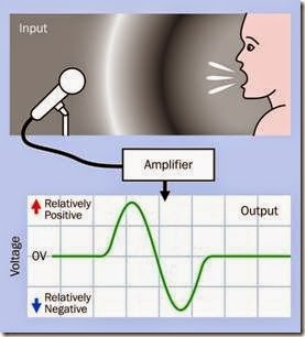
Naturally occurring sounds can be converted to fluctuations in voltage by a microphone, which will be found listed as a sensor in Volume 3 of this encyclopedia. Artificial sounds can be generated as voltage fluctuations by oscillators and other electronic circuits. In either case, the output fluctuations can range between an upper limit set by a positive supply voltage and a lower limit established by electrical ground (which is assumed to be 0 volts). Alternatively, the fluctuations can range between the positive supply voltage and an equal and opposite negative supply voltage, with 0V lying midway between the two. This op- tion can be less convenient electrically but is a more direct representation of sound, because sound waves fluctuate above and below ambient air pressure, which can be considered analogous to a ground state.

The concept of positive and negative sound waves is illustrated in Figure 29-2 (originally published in the book Make: More Electronics).

clip_image008

Figure 29-2. The use of positive and negative voltages to represent a wave of high sound pressure followed by a trough of lower pressure.

The topic of sound amplification is explored in detail in the entry on op-amps in Chapter 7.

A headphone inverts the function of a micro- phone by converting electricity back into air- pressure waves. This is done electromagnetically (moving a diaphragm in response to an electro- magnet) or electrostatically (moving a membrane in response to electrostatic force between two charged electrodes).

Variants
Moving Coil

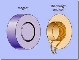
The most enduringly popular type of headphone uses a coil attached to a diaphragm. This is known as a moving-coil headphone, as the coil moves with the diaphragm. It can also be referred to as having a dynamic driver or dynamic transducer, “dynamic” referring to the movement of the coil.

The moving-coil concept is illustrated in Figure 29-3. The coil slides into a deep, narrow, circular slot in a magnet that is attached to the plastic frame of the headphone. The diaphragm is supported at its edges by a flexible rim. Variations in current passing through the coil create a fluctuating magnetic field that interacts with the field of the fixed magnet, causing the diaphragm to move in and out. A very similar configuration is used in many loudspeakers. Detail modifications may be made to increase efficiency, reduce production costs, or enhance sound quality, but the principle remains the same.

clip_image010

Figure 29-3. The basic elements of a moving-coil head- phone.

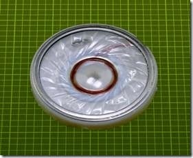
The internal element of a headphone is shown in Figure 29-4. A plastic diaphragm is visible, measuring slightly less than 2” in diameter. The mag- net and coil are concealed underneath.

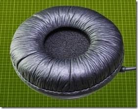
The element in the previous figure is normally enclosed in an assembly such as the one in Figure 29-5, which incorporates a soft padded rim to rest upon the ear.

In an effort to achieve a more balanced frequency response, some designs use two moving-coil drivers in each headphone, optimized for low frequencies and high frequencies, respectively.

Earbuds, described after the next section, often use a miniaturized version of the moving-coil design.

clip_image012

Figure 29-4. The sound reproducing element removed from a headphone.

clip_image014

Figure 29-5. The sound reproducing element from the previous figure is normally packaged inside this enclosure.

Other Types

Electrostatic headphones use a thin, flat diaphragm suspended between two grids that function as electrodes. A fluctuating potential between the grids, coupled with a reverse-phase voltage on the diaphragm, will vibrate the diaphragm, generating pressure waves. A relatively high voltage is necessary to achieve this, any- where from 100V to 1,000V, supplied through a conversion unit between the headphones and an amplifier. Electrostatic headphones are known for low distortion and an excellent high frequency response, at some extra cost.

Electret headphones work on a similar principle, except that the membrane is permanently charged, and a high voltage is not required. Electret headphones tend to be small, inexpensive, and not of high sound quality.

A balanced armature design, often referred to by the acronym BA, uses a pivoting magnet that is claimed to increase efficiency while reducing stress on a diaphragm. BA drivers can be extremely compact, contained within a sealed met- al enclosure measuring less than 10mm x 10mm x 5mm. They are commonly used in conjunction with in-ear earphones, described in the next section.

Mechanical Design

Circumaural headphones use large soft pads to encircle the ear and block external noise. Their size tends to make them heavy, requiring a well- designed headband to provide comfortable sup- port. Supra-aural headphones are smaller and lighter, resting on the ears instead of enclosing them. They cannot exclude ambient noise, and may have inferior bass response compared with the circumaural type.

Open-back headphones, also known as acoustically transparent, are favored by some audiophiles because their vented outer surfaces are thought to create a more natural sound, similar to that of a speaker. The open backs naturally allow ambient noise to intrude, but also allow the sound generated by the headphones to be heard by others in a room. Closed-back headphones contain their sound and provide more insulation against ambient noise.

Earbuds rest just within the outer folds of the ear, facing inward like a pair of tiny speakers. They are easily dislodged and provide very little insulation against ambient noise. Their use became common after the introduction of Apple’s iPod. A pair of earbuds, one of them with its plastic cover removed, is shown in Figure 29-6.

clip_image016

Figure 29-6. A pair of earbuds, one with its cover re- moved to show the sound reproducing element, which closely resembles the diaphragm in a full-sized head- phone.

In-ear headphones are designed for insertion into the ear canal, often using a soft sheath that con- forms with the ear like an earplug. This sheath is disposable for hygienic reasons, and because it may lose some of its plasticity with use. It excludes most ambient noise, and by minimizing the air gap between the driver of the headphone and the ear drum enables a high quality of sound reproduction.

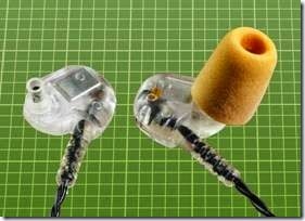
In-ear headphones are also known as in-ear monitors, IEMs, ear canal headphones, earphones, and canalphones. A pair of in-ear headphones is shown in Figure 29-7, one of them with its foam sheath removed. The rectangular silver-colored object in the headphone on the left contains a transducer to create sound pressure.

A headset consists of one or two headphones plus a flexible microphone that extends to the promiximity of the mouth of the user.

Noise-cancelling headphones, popularized by Bose, monitor external noise with a built-in microphone and generate sound of opposite phase, to provide some cancellation. They are particularly effective on jet aircraft, where back- ground noise tends to be consistent.

clip_image018

Figure 29-7. A pair of in-ear headphones, supplied with disposable foam plugs that conform flexibly with the ear canal. The headphone on the left is shown with its plug re- moved.

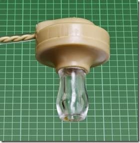
Although an earphone is almost obsolete, it is still obtainable from specialty suppliers. It has a high impedance, making it suitable for use with a crystal-set radio. An earphone is pictured in Figure 29-8.

clip_image020

Figure 29-8. A vintage earphone of the type suitable for use with a crystal-set radio.

Values
Intensity

Sound pressure is measured in decibels. For a complete explanation and discussion of weigh- ted and unweighted decibel scales, see “Sound Pressure” on page 251 in the transducer entry.

Frequency Response

A plot of sound pressure as a function of frequency shows the frequency response of a head- phone. Measuring the sound pressure meaning- fully is a challenge, because the ear canal will add coloration to the sound and can amplify some frequencies while masking others. Ideally, measurement should be done at the ear drum, but this is not feasible. Consequently, high-end head- phones are evaluated by making sound measurements inside simulated ear canals in a dummy human head.

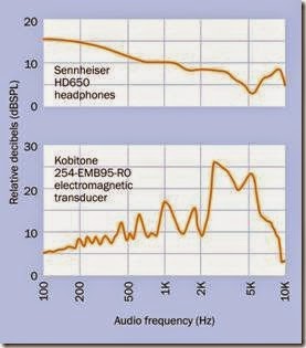
A comparison between a high-quality $500 audio product and a transducer that is sold as a component for less than $1 illustrates the difference in frequency response; see Figure 29-9. The Sennheiser headphones have a smooth response that rises toward the low end, compensating for the lack of bass response that tends to be a problem in headphones, and the relative in- sensitivity of the human ear to low frequencies. The fluctuations at the high end are within about 5dB.

By comparison, the Kobitone emphasizes the range between 3kHz and 4kHz because its primary task is to be heard, and these are the frequencies where human hearing is most sensitive. Its low-frequency response trails off (although is still much better than that of a piezoelectric transducer, where the low response typically diminishes by 40dB to 50dB). The low-frequency output of the Kobitone is actually impressive bearing in mind that the component is only 9mm in diameter. It draws 60mA at 5VAC.

clip_image022

Figure 29-9. Comparison between frequency responses of a $1 electromagnetic transducer intended as an audio alert and a $500 pair of headphones intended for sound reproduction. The upper graph is derived from a review online at headroom.com; the lower graph is from the manufacturer’s datasheet.

Some manufacturers of audio reproduction equipment prefer not to supply frequency response curves. Instead they may claim, for ex- ample, that the frequency response of a product ranges from 100Hz to 20kHz. This claim means very little unless it is accompanied by a range of sound pressure levels. If the frequency response is consistent within a range of, say, plus-or-minus 5dB, this may be acceptable. If the range is plus- or-minus 20dB, it is not acceptable. The ability to reproduce a high note or a low note is not useful if the sound is too faint to hear.

Distortion

The total harmonic distortion (THD) of any audio equipment measures its tendency to add spuri- ous harmonics of a single frequency. If head- phones are required to reproduce a pure 1kHz sinewave, they will also tend to create an addi- tional 3kHz tone that is an artifact. This can be caused by the mechanical behavior of a vibrating diaphragm. The human ear recognizes distortion as a fuzzy or rasping sound. A square wave the- oretically contains all the harmonics that are odd multiples of its fundamental frequency, and sounds extremely distorted.

THD should be less than 1% in good-quality au- dio devices.

Impedance

The electrical impedance of headphones is relevant in that it should match the output specifi- cation of the amplifier that drives them.

What Can Go Wrong
Overdriving

Headphones can be damaged by overdriving them. Because a low frequency requires larger excursions of a diaphragm to transmit the same energy as a high frequency, headphones are especially vulnerable to being damaged by bass at high volume.

Hearing Damage

Human hearing can be damaged by prolonged listening to headphones at a high volume. Some controversy remains regarding an acceptable limit for sound pressure.

Mismatched Impedance

If the impedance of headphones does not match the output of the amplifier driving them, distortion or a skewed frequency response can result. This is known as mismatching.

Incorrect Wiring

In most consumer products, a pair of head- phones will share a common ground. While the connections in a typical three-layer jack plug have been standardized, hand-wired repairs or extensions should be tested carefully. Incorrect wiring will cause unpredictable results.


audio indicator:What It Does,Audio Frequency,History,Variants,Sound Patterns,Formats,Values,Voltage,Current and Frequency.

audio indicator

An audio indicator is defined here as a noise-creation device that generates a simple tone or series of tones. Unlike a transducer, which requires an external source of AC to determine its audio frequency, an indicator contains its own electronics and requires only a DC power supply. Either of these components is often described as a beeper or buzzer.

While piezoelectric alerts formerly used crystals, only the more modern piezoelectric type that uses a ceramic wafer will be considered here.

What It Does

When DC power is applied to an audio indicator, in its simplest form it creates a continuous or intermittent tone of a fixed frequency. This is called an alert.

Audio alerts are used in microwave ovens, washer/dryers, automobiles, gasoline pumps, security devices, toys, phones, and many other consumer products. They are often applied with touch pads, to provide audio confirmation that a tactile switch has been pressed.
A few indicators are programmed to create a two-tone sound, or multiple-tone sequences.
See Figure 27-1 in the previous entry for an assortment of schematic symbols that may be used to represent either an alert or a transducer.
How It Works

from around 0.5” to 1.5” in diameter. The enclosure is sealed at the bottom but has a small hole at the top, so that sound can emerge from the upper side of the diaphragm without being partially cancelled by sound of opposite phase that is emitted from the underside of the diaphragm. The enclosure also contains electronics to generate one or more audio tones, and amplifies the sound by resonating with it, in the same way that the body of a guitar or violin amplifies a note being played on the strings.

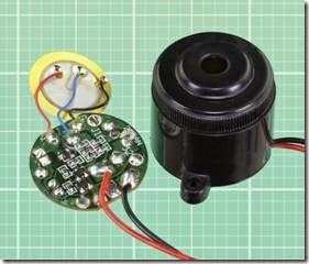
A PUI XL453 piezoelectric audio indicator is pictured in Figure 28-1, fully assembled on the right, and with its circuit board and diaphragm re- moved on the left. This indicator creates a pulsed tone at 3.5kHz with a sound pressure of 96dB. It draws 6mA at 12VDC and measures approximately 1” in diameter.

For more information about the measurement of sound frequency and pressure, see “Frequency A circular diaphragm is glued at its edges inside a cylindrical plastic enclosure, usually measuring Range” on page 251 and “Sound Pressure” on page 251 in the previous entry.

clip_image005

Figure 28-1. A typical piezoelectric audio indicator.

Externally, an audio indicator may be indistinguishable from a transducer. However, internally, an indicator is almost always a piezoelectric de- vice, in which a ceramic wafer is mounted on a thin brass diaphragm. The term piezo is derived from the Greek piezein, which means to squeeze or press.

A transducer (described in the previous entry) is a piezoelectric or electromagnetic alert that does not usually contain its own circuitry and must be driven by an external source of AC, which establishes the audio frequency.

The distinction between an indicator and a transducer is often unclear in parts catalogs, where all alerts may be identified as buzzers, even though they mostly beep rather than buzz.

Audio Frequency

For a discussion of audio frequency, see “Fre- quency Range” on page 251 in the previous en- try.

History

Probably the earliest form of electrically activated alert was the door bell, in which a 6VDC battery-powered solenoid pulled a springloaded lever terminating in a small hammer. The hammer struck the bell, but the motion of the lever also opened a pair of contacts, cutting off power to the solenoid. The lever sprang back to its rest position, which closed the contacts and repeated the cycle so long as power was supplied through an external pushbutton.

Subsequent systems used a small loudspeaker powered by AC house current through a step- down transformer. This created a buzzing sound and may have been the origin of the term “buzzer.”

Small components that made a beeping sound only became common when digital equipment required a simple, cheap way to confirm user in- put or attract attention to the status of a device.

Variants
Sound Patterns

Because an audio indicator contains its own electronics, the manufacturer has the freedom to create various patterns of sound output.

The default is a steady tone. Other common variants include an intermittent tone and a dual tone that fluctuates rapidly between two frequencies. This is sometimes referred to as a siren. A few variants can generate an output pat- tern consisting of several tones in sequence, or effects such as warbling or whooping sounds, which are used mainly in alarm systems.

Formats

Some audio indicators are available in surface- mount format, measuring 1/2” square or less. Be- cause the resonant frequency is related to the size of the component, surface-mount alerts usu- ally make a high-pitched beep.

Panel-mount and board-mount formats range from about 1/2” to 1.5” in diameter. A small audio alert designed to be mounted on a circuit board is shown in Figure 28-2, with its top removed on the right to expose the brass diaphragm glued around the edges. The same component is shown with its plastic enclosure removed completely in Figure 28-3.

clip_image008

Figure 28-2. An audio indicator approximately 0.5” in diameter, partially disassembled on the right, revealing its brass diaphragm.

clip_image010

Figure 28-3. The same indicator from the previous photograph, with its enclosure completely removed.

Values

For an explanation and discussion of sound pressure and its measurement in decibels, see “Sound Pressure” on page 251 in the previous entry.

Audio indicators generally have a sound pressure rating in dBSPL ranging between 65dBSPL to 95dBSPL, with just a few products that make more or less noise. At 120dB and above, most products are packaged as alarm sirens ready for installation, often with a small horn attached. Their power consumption can be 200mA or

more, and they are many times the price of a simple indicator designed for circuit-board mounting.

Voltage

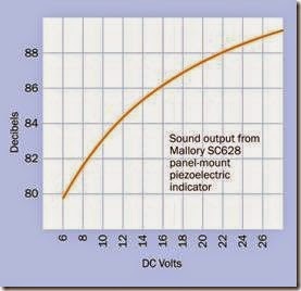
An audio indicator containing its own electronics will almost always be rated somewhere in the range from 5VDC to 24VDC. Sirens intended for use with burglar alarms are often designed for 12VDC or 24VDC, as these are popular values for security systems with battery backup. However, in addition to a rated voltage, a datasheet may specify a wide range of acceptable operating voltages. For example, an indicator with a rated voltage of 12VDC may have an operating voltage of 3VDC to 24VDC. Naturally, the sound intensity will vary with the voltage, but not as much as one might assume. The graph at Figure 28-4 shows that the sound output from an alarm, measured in decibels, increases by only 8dB when voltage increases by almost a factor of five. Of course, the decibel scale is not linear, but human perception of sound is not linear, either.

clip_image013

Figure 28-4. Variation of sound output relative to voltage, in a commonly used piezoelectric indicator.

Current

Typical piezoelectric indicators use less than 10mA (often as little as 5mA) and generate negligible heat.

Frequency

The most common frequencies for indicators range between 3kHz and 3.5kHz. Piezoelectric elements are inefficient for generating sounds below 1kHz.

Duty Cycle

Piezoelectric alerts generate very little heat and can be run on a 100% duty cycle.

If an alert will be pulsed briefly, the minimum pulse time is 50ms. A shorter duration will merely generate a clicking sound.

How to Use It
Appropriate Sound Intensity

An indicator should be chosen with reference to the environment in which it will be used. To be easily heard, it should be at least 10 dB louder than the ambient background noise.

Volume Control

Sound intensity can be reduced by reducing the voltage. Because an indicator does not consume much current, a trimmer can serve as a volume control. Alternatively, a rotary switch with a set of fixed-value resistors can select preset sound values.

However, in many indicators, variations in volt- age may have relatively little effect on sound output, as shown in Figure 28-4.

Wiring

An indicator requires DC voltage. Because the indicator contains a transistor, polarity of the power supply is important. If the indicator has leads attached, the one intended for connection to the positive side of the power supply will be red. If it has pins, the longer pin will be for the positive connection.

What Can Go Wrong

The potential problems in an indicator are the same as those for a transducer. See “What Can Go Wrong” on page 254 in the previous entry.


transducer:What It Does,How It Works,Variants,Electromagnetic,Piezoelectric,Ultrasonic Transducer,Measurement Location,Limitations,Voltage and Current.

transducer

The term transducer is used here to describe a noise-creating device that is driven by external electronics. By comparison, an audio indicator (discussed in the next entry) contains its own internal electronics and only requires a DC power supply. Either of these components is often described as a beeper or buzzer.

A speaker, more properly termed a loudspeaker, is an electromagnetic transducer but is seldom described in those terms. It has a separate entry in this encyclopedia and is defined here as a sound reproduction device that is larger and more powerful than a typical transducer and has a more linear frequency response.

While piezoelectric transducers formerly used crystals, only the more modern piezo- electric type that uses a ceramic wafer will be considered here.

Some transducers convert sound into electricity, but these are categorized as sensors, and will be discussed in Volume 3. The only transducers discussed in this entry are those that convert electricity into sound.

What It Does

An audio transducer is a device that can create an alert. It requires an AC signal that is supplied by external electronics, and in its simplest form may be referred to as a buzzer or a beeper.

Audio alerts are used in microwave ovens, washer/dryers, automobiles, gasoline pumps, security devices, toys, phones, and many other consumer

tones. Type A is probably the most popular symbol. Types B and C often appear with the word “buzzer” printed beside them for clarification. D and E are really symbols for a speaker, but are often used for an alert. F is the symbol for a crystal, now sometimes used to indicate a piezoelectric noise maker. G specifically represents an electromagnetic transducer, but is seldom used.

How It Works

products. They are often used in conjunction  with touch pads, to provide audio confirmation that a tactile switch has been pressed.

The schematic symbols in Figure 27-1 can be used to represent any kind of audio alert, includ- ing indicators, which contain their own electronics to generate a simple tone or series of A circular diaphragm is glued at its edges inside a cylindrical plastic enclosure, usually measuring from around 0.5” to 1.5” in diameter. The enclosure is sealed at the bottom but has an opening at the top, so that sound can emerge from the upper side of the diaphragm without being partially cancelled by sound of opposite phase that is emitted from the underside of the diaphragm. The enclosure also amplifies the sound by resonating with it, in the same way that the body of a guitar or violin amplifies a note being played on the strings.

clip_image005

Figure 27-1. An assortment of symbols which can repre- sent a transducer or an indicator. See text for details.

The diaphragm is activated either electromagnetically or piezoelectrically, as described next.

Externally, a transducer may be indistinguishable from an audio indicator such as the one pic- tured at Figure 28-1.

Variants
Electromagnetic

An electromagnetic transducer contains a diaphragm that is usually made of plastic. Mounted on it is a smaller ferromagnetic disc that responds to the fluctuating field from AC passing through a coil. When the diaphragm vibrates, it creates pressure waves that are perceived by the human ear as sound.

A car horn is a particularly loud form of electro- magnetic transducer.

Piezoelectric

A piezoelectric transducer contains a diaphragm consisting of a thin brass disc on which is moun- ted a ceramic wafer. When an AC signal is applied between the piezoelectric wafer and the disc, the disc flexes at that frequency.

The term piezo is derived from the Greek piezein, which means “to squeeze or press.”

Ultrasonic Transducer

The diaphragm in an ultrasonic transducer vibrates at a frequency above the range of human hearing. This component may be electromagnetic, piezoelectric, or crystal-based. Often it is used in conjunction with an ultrasonic receiver as a distance measuring device. The two components can be sold pre-mounted on a breakout board. An output from the board can consist of a pulse train where the pulse duration is proportional to the distance between the transducer and the nearest sound-reflecting object.

An ultrasonic transducer is pictured in Figure 27-2. Its internal components are shown in Figure 27-3.

clip_image008

Figure 27-2. The exterior of an ultrasonic transducer.

Submersible ultrasonic transducers may be used in cleaning systems, where they agitate a liquid that dislodges dirt or debris. Ultrasonic transducers are also used in echo-sounding and sonar equipment with marine applications.

clip_image010

Figure 27-3. Inside an ultrasonic transducer, a small aluminum cone is the sound radiating element. The white blobs are adhesive to secure the thin wires.

Formats

Some transducers are available in surface-mount format, measuring about 0.5” square or less. Be- cause the resonant frequency is related to the size of the component, surface-mount transducers usually generate a high-pitched beep.

Values
Frequency Range

Audio frequency is measured in Hertz, abbreviated Hz, named after Heinrich Rudolf Hertz, the first scientist to prove the existence of electro- magnetic waves. The H in Hz is capitalized be- cause it refers to a real name. One thousand Hertz can be written as 1 kiloHertz, almost always abbreviated as 1kHz (note that the k is lowercase).

The human ear is often described as being able to detect sounds between 20Hz and 20kHz, al- though the ability to hear sounds above 15kHz is relatively unusual and diminishes naturally with age. Sensitivity to all frequencies can be impaired by long-term exposure to loud noise.

The most common frequencies applied to audio transducers range between 3kHz and 3.5kHz.

Piezoelectric elements are inefficient for generating sounds below 1kHz, but electromagnetic transducers are better able to generate lower frequencies. Their response curve can be approximately flat to frequencies as low as 100Hz.

Sound Pressure

Sound pressure can be measured in Newtons per square meter, often abbreviated as Pa. Newtons are units of force, while Pa is an abbreviation of Pascals.

The sound pressure level (SPL) of a sound is not the same as its sound pressure. SPL is a logarithmic value, to base 10, in units of decibels (dB), derived from the pressure of a sound wave relative to an arbitrary reference value, which is 20 micro-Pascals (20µPa). This is the agreed minimum threshold of human hearing, comparable to a mosquito at a distance of three meters. It is assigned the level of 0dB.

Because the decibel scale is logarithmic, a linear increase in the decibel level of a sound does not correspond with a linear increase in actual sound pressure:

• For each additional 6dB in the SPL, the actual sound pressure approximately doubles.

• For each additional 20dB in the SPL, the actual sound pressure is multipled by 10.

Bearing in mind that 0dB corresponds with the reference sound pressure of 20µPa, an SPL of 20dB represents a sound pressure of 200µPa (that is 0.0002Pa), and so on.

Many tables show an estimated decibel level for various noise sources. Unfortunately, these tables may contradict each other, or may fail to mention the distance at which a sound is measured. Figure 27-4 shows estimates derived by averaging eight similar tables. It should be viewed as an approximate guide.

clip_image013

Figure 27-4. Approximate decibel values for some sound sources (averaged from a selection of eight similar charts).

Sometimes the claim is made that an increase of +10 on the decibel scale will correspond with a subjective experience that the noise is “twice as loud.” Unfortunately, this statement cannot be quantified.

Weighted Sound Values

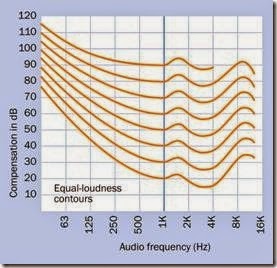
Subjective assessment of sound is complicated by the nonlinear frequency response of the hu- man ear, which causes some frequencies to seem “louder” than others, even though their sound pressure is the same. The frequency weighting of the ear can be determined by playing a reference tone of 1kHz at 20dB and then doing an A-B comparison with a secondary tone at another frequency, asking the subject to adjust the gain of the secondary tone up or down until the two tones seem equally loud.

This procedure is performed for a range of frequencies. The test is then repeated with a louder 1kHz reference tone, at 30dB. Repetitions continue to a final reference tone of 90dB.

The resulting curves are known as equal-loudness contours. An averaged set, from multiple sources, has become an international standard with ISO number 226:2003. The curves shown in Figure 27-5 are derived from that standard. The curves show that the sound pressure of lower frequencies must be boosted by a significant amount to sound as loud as a 1kHz frequency, while a frequency around 3kHz must be reduced slightly, because it tends to sound louder than all others.

clip_image015

Figure 27-5. Equal loudness contours derived from ISO 226:2003. See text for details.

Although the accuracy of equal-loudness con- tours is controversial, they have been the basis of a widely used weighting system to adjust dB values to represent subjective perceptions of loudness. This A-weighting system remains the best-known and most widely applied audio standard in the United States, even though it has been criticized for assigning too little value to sounds that are brief in duration. If a sound level is expressed in dBA, it is A-weighted, meaning that the sounds to which the ear is least sensitive are assigned a value that is lower than their measured value. Thus, a tone of 100Hz has a dBA value about 20dB lower than its dB value, be- cause the human ear is relatively insensitive to low-pitched sounds. dBA values are used in reg- ulations that limit noise in the work place and other environments.

Unweighted Values

If sound intensity is expressed in dBSPL, it is a measurement of the actual Sound Pressure Level and has not been adjusted with the A-weighting system. A graph of unadjusted dbSPL values will display low frequencies as if they are more in- tense than the ear will perceive. In practical terms, subjective perception of low-end rolloff will be even more severe than the graph makes it appear.

If sound intensity is expressed merely in dB, probably it is unweighted and should be considered as dBSPL.

From a practical point of view, when choosing a tone for a transducer, a 500Hz tone may sound relatively mellow and not subjectively loud. A 3.5kHz tone can be a good attention-getting sig- nal, as the ear is most sensitive in that range.

Transducers generally have a sound pressure rat- ing in dBSPL ranging between 65dBSPL to 95dBSPL, with just a few products that can make more or less noise.

Measurement Location

The sound pressure from an audio alert will naturally diminish if the measurement point moves farther away. Therefore, any rating in decibels should be expressed with reference to the distance at which the measurement is made.

Measurement locations may be expressed in centimeters or inches, and may vary from 10cm to 1 meter, even in datasheets for different devi- ces from the same manufacturer. If the measurement distance doubles, the SPL diminishes by approximately 6dB.

Limitations

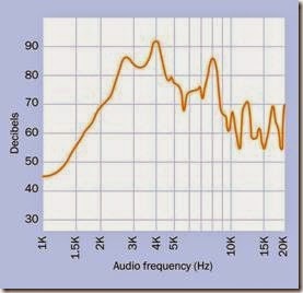
A piezoelectric transducer is not intended as a sound reproducer, and does not have a smooth or flat frequency response. The curve for the Mallory PT-2040PQ is not unusual, reproduced in Figure 27-6. This component measures about 3/4” in diameter, is rated for 5VDC, and uses only 1.5mA to generate 90dB (measured at a distance of 10cm). Like many piezoelectric audio devices, its response peaks around 3500kHz and diminishes above and below that value, especially to- ward the low end. While it is perfectly adequate as a “beeper,” it will not reproduce music successfully.

clip_image017

Figure 27-6. The frequency response from a typical small piezoelectric transducer.

An electromagnetic transducer is better able to generate low frequencies than a piezoelectric transducer. It has a low impedance that may be suitable in some circuits. However, it is slightly heavier than a comparable piezoelectric transducer, uses much more power, and as an AC de- vice containing a coil, it can create electromagetic interference or may cause fluctuations in the circuit as an inductive load. It is also vulnerable to magnetic interference from elsewhere, while a piezoelectric transducer is not.

While an electromagnetic transducer can be used to reproduce speech or music, and will do a better job than a piezoelectric transducer, its performance will still be dissatisfying. A miniature speaker is more appropriate for the task.

Voltage

Transducers are typically designed to work with voltages ranging from 5VAC to 24VAC. The ceramic wafer in a piezoelectric transducer usually cannot withstand voltages much above 40VAC, and its sound output will not increase significantly above 30VAC.

Current

Typical piezoelectric transducers use less than 10mA and generate negligible heat. An electro- magnetic transducer may draw as much as 60mA.

How to Use It
Appropriate Sound Intensity

An alert should be chosen with reference to the environment in which it will be used. To be easily heard, it should be at least 10 dB louder than ambient background noise.

Volume Control

Sound pressure can be lowered by reducing the voltage. Because a transducer does not consume much current, a trimmer can serve as a volume control. Alternatively, a rotary switch with a set of fixed-value resistors can select preset sound values.

AC Supply

Although a transducer is an AC device, it is un- likely to be designed for voltage that fluctuates positively and negatively either side of a neutral value. Typically it is intended for voltage that fluctuates between 0V (ground) and the rated positive value of the power supply, and its pins, wires, or terminals are usually marked accordingly. If it has wire leads, the red lead should be connected to the more-positive side of the sup- ply. If it has pins, the longer pin should be more positive.

The alternating signal for a transducer can be supplied by any simple oscillator or astable multivibrator circuit. For a given peak voltage, a square wave will generate a louder signal than a sinusoidal wave. A simple 555 timer circuit can be used, with a second monostable timer to limit the duration of the beep if necessary. An astable 555 can be used to test the transducer and select the audio frequency that sounds best.

Self-Drive Transducer Circuit

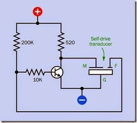
If a transducer has three wires or pins, it is prob- ably a self-drive type. The datasheet may identify its inputs as M, G, and F, meaning Main, Ground, and Feedback. The Feedback terminal is connected with a section of the diaphragm which vi- brates 180 degrees out of phase with the Main terminal. This facilitates a very simple external drive circuit, such as that in Figure 27-7, where the frequency is determined by the transducer’s resonant frequency.

clip_image019

Figure 27-7. A circuit to control a self-drive type of piezo- electric transducer.

What Can Go Wrong
Overvoltage

Mallory Sonalerts, one of the largest producer of piezoelectric alerts, states that in the “vast majority” of returned products, the failure was caused by excessive voltage, often in the form of a transient voltage spike.

Leakage

If an alert makes a small, low-volume sound when it is supposed to be off, some current is leaking through it. Less than 1mA may be enough to cause this problem. According to one manufacturer, it can be fixed by placing a 30V Zener transient voltage suppressor diode in ser- ies with the alert, or by wiring a small incandescent lamp in parallel with the alert.

Note that when the alert is activated, the full supply voltage will be seen at the lamp.

Component Mounting Problems Some alerts are packaged with mounting holes, but many are not. Those with pins can be soldered into a board, but those without must be

glued in place or inserted into a cavity from which they cannot shake loose. Silicone adhesive is recommended, but care must be taken to avoid any of it dripping into the alert before it sets.

Moisture

If an alert will be used in a location where it is vulnerable to moisture, it should be of a type that is sealed against the environment. Even a sealed unit should ideally be oriented so that it faces slightly downward.

Transducer-Indicator Confusion Externally, a transducer and an indicator often look identical, and some of them are not marked with a manufacturer’s part number. Damage can be caused by applying DC to a transducer or AC to an indicator. If both types of parts are kept in inventory, they should be carefully labeled.

Connection with a Microcontroller A piezoelectric transducer can be driven by a mi- crocontroller, but an electromagnetic transducer is not appropriate in that role, because of its relatively higher current consumption and its behavior as an inductive load.


electroluminescence:What It Does,How It Works,Phosphors,Derivation,Variants,Panels,Flexible Ribbons,Rope Light and OLED.

electroluminescence

The field of electroluminescent devices is sometimes referred to as EL. The same acronym can also be applied as an adjective to an individual electroluminescent device, as in, for example, “an EL panel.”

An organic light-emitting diode, more commonly known by its acronym OLED, is included in this entry because it is technically an electroluminescent device and its design concept is similar to that of an electroluminescent panel. Generic LEDs are also technically electroluminescent, but are not commonly described as such, and have their own entries in this encyclopedia under the subject categories LED indicator, LED area lighting, and LED display.

What It Does

An electroluminescent device configured as a panel, ribbon, or rope-light contains phosphors that emit light in response to a flow of electricity.

Panels can be used as backlights for LCD displays or, more often, as always-on low-power devices such as exit signs and night lights. Ribbons and rope lights (the latter being also known, more accurately, as light wires) are used mainly as recreational novelties. They can be battery powered through a suitable voltage converter. A battery- powered rope light can be wearable.

Thin-film OLED electroluminescent panels are used in small video screens in handheld devices. At the time of writing, OLED TV screens measuring 50” or more have been demonstrated, but are not yet economic for mass production.

No specific schematic symbol exists to represent any electroluminescent device or component.

How It Works

Luminescence is the emission of light as a result of a process that does not require heat. (The opposite phenomenon is incandescence, in which heating causes an object to emit light; see Chapter 18 for a description of incandescent lamps.)

Electroluminescence is luminescence resulting from stimulation by electricity. This very broad definition really includes devices such as LEDs, although they are hardly ever described in those terms. Electroluminescence generally refers to panels, films, or wires where electrodes are in direct contact with light emitters such as phosphors.

The exception is an organic LED, usually known by its acronym OLED, which is frequently de-scribed as an electroluminescent device, per- haps because its configuration as a sandwich of thin, flat layers resembles an electroluminescent panel. Two of the layers are semiconductors, and they interact as light-emitting diodes.

Phosphors

A phosphor is a compound such as zinc sulfide that will emit light when it receives an energy input from another light source or from electricity. Typically the compound must be mixed with an activator such as copper or silver.

For many decades, TV sets and video monitors were built around cathode-ray tubes in which the interior of the screen, at the front of the tube, was coated with phosphors. A beam of electrons that fluctuated in intensity generated a picture on the screen by drawing it as a series of lines.

Derivation

The term phosphor is derived from phosphorescence, which in turn comes from the name of the element phosphorous, which will glow when it oxidizes in moist air. (These terms were established before other forms of luminescence were discovered and understood. The behavior of phosphorous is really an example of chemiluminscence.)

For our purposes, a phosphor is a compound that is capable of fluorescence or electroluminescence.

Variants
Panels

Electroluminescent panels using phosphor powder, sometimes referred to as thick phosphor, are a popular choice where a constant, uniform, low light output is acceptable.

An electric potential is established between two films that act as electrodes, separated by a layer of phosphor crystals. Some manufacturers refer to this configuration as a light-emitting capacitor because the structure resembles a capacitor, even though that is not its purpose. The front film is transparent, allowing light to escape.

An electroluminescent panel can be powered by AC or DC but requires at least 75V. Its power consumption is self-limiting, so that no control electronics are required other than a voltage converter if battery power is used.

The phosphors generate a constant, evenly distributed luminescence over the entire area, al- though the output is not very intense. Applications include night-lights, exit signs, and back- lighting for wristwatches.

Panelescent electroluminescent lighting by Sylvania was used for instrument panel displays in some car models such as the Chrysler Saratoga (1960 through 1963) and Dodge Charger (1966 through 1967). It is still used for night-lights. Indiglo electroluminiscent displays are still widely used in wristwatches.

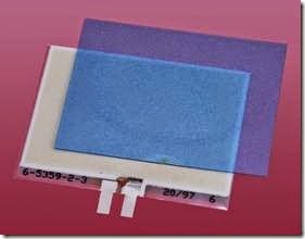
The interior components of a disassembled elec- troluminescent night-light are shown in Figure 26-1. The panel emits a natural pale green glow. A separate blue or green filter passes the glow while blocking other colors of incident light that would otherwise reflect off the panel.

clip_image007

Figure 26-1. The two interior components of an electroluminiscent night-light: the luminescent panel, and a separate translucent filter.

Electroluminescent night-lights were popular in the 1970s and 1980s, often featuring cartoon characters to appeal to children. Figures 26-2 and 26-3 show the same night-light in its daytime off- state and its night-time on-state, respectively.

clip_image009

Figure 26-2. A vintage Panelescent brand night-light, several decades old, in its off-state.

clip_image011

Figure 26-3. The same night-light, with its green radiance visible under conditions of low ambient light.

Advantages of electroluminescent panels include the following:

• Low current consumption. One US manufacturer claims that a single exit sign will use electricity costing less than 20 cents per year, while the annual cost of a night-light will be less than 3 cents per year.

• Long life, up to 50,000 hours.

• Self-regulating; no control circuitry required.

• Omnidirectional light output.

• Very wide operational temperature range, between approximately -60 and +90 de- grees Celsius.

• Can be plugged directly into a wall outlet. Disadvantages include:

• Limited light output.

• Very limited choice of colors.

• Not very efficient, 2 to 6 lumens per watt (al- though the low light output naturally entails low power consumption).

• Gradual reduction in phosphor performance over time.

• High voltage required: 60V to 600V. Ideal for plugging into a wall outlet, but requires a converter when used with battery-powered devices.

Flexible Ribbons

The light-emitting layers inside a night-light are somewhat flexible, and can be made more flexible by reducing their thickness. The result is an electroluminescent ribbon that has some novelty value, and may be used for customizing auto- mobiles. Figure 26-4 shows a ribbon about 1.5” wide and 12” long, designed for 12VDC power applied through an inverter.

Rope Light

A rope light or wire light may resemble a glow- stick. However, a glowstick generates light from chemiluminescence (chemical reactions that re- lease photons), while a rope light uses electricity.

Figure 26-5 shows a rope light powered by two AA batteries connected through an inverter.

At the center of the rope light is a conductor that serves as one electrode. It is coated in phosphors, and the layer of phosphors is protected by a transparent sheath. One or more thin wires is wrapped around the sheath in a spiral, with large gaps between one turn and the next. These wires serve as the second electrode. The wires are en- closed in transparent insulation that forms an outer sheath.

clip_image013

Figure 26-4. A 12” length of electroluminescent ribbon.

When AC is applied between the electrodes, the layer of phosphors emits light that radiates out in the gaps between the thin wires. The color of the light can be modified by using tinted outer insulation.

OLED

An OLED uses two thin, flat electrodes, some- what like a thick-phosphor electroluminescent panel, except that it contains more layers and is capable of generating more light. The layers in an OLED are “organic” in that they consist of chemically organic molecules containing carbon and hydrogen atoms and generally do not contain heavy metals.

While an LCD video monitor or TV screen must have a separate backlight, an OLED generates its own light. This reduces the thickness of the dis- play to a few millimeters and makes it potentially more efficient.

The semiconductor layers are subdivided into pixels, each functioning as a light-emitting di- ode, while additional layers carry a matrix of conductors for pixel addressing. In an AMOLED, the conductors form an active matrix, while in a PMOLED, they form a passive matrix.

clip_image015

Figure 26-5. A length of glowing rope light, also known as a light wire.

In an active matrix, each pixel is backed with a thin-film transistor to store its state while the energizing voltage transitions. This is often de- scribed as a TFT display; but the term is interchangable with “active matrix.”

In a passive matrix, each pair of conductors simply supplies current to a pixel. This is cheaper and easier to fabricate but is less responsive.

The terms “active matrix” and “passive matrix” have the same meaning as when used to de- scribe a liquid-crystal display.

Monochrome OLED display modules with dot- matrix characters are currently available from China for just a few dollars. Although they appear superficially similar to LCD modules, they generate pure white-on-black characters.

Small full-color OLED screens are used in smart- phones and on camera backs, but at the time of writing, large OLED screens are not a mature technology, partly because of production costs. A great variety of chemicals and layer configurations have been tried, and the application of pixels to a substrate has been attempted with vacuum deposition through a shadow mask and with a system similar to inkjet printing. Pixels that emit red, green, and blue light have also been used. Filtered pixels have been used. One dominant process has not yet emerged.

Longevity and brightness have been problems. Where red, green, and blue diodes have been

used, the different colors deteriorate at different rates. While the human eye tolerates an overall reduction in brightness, it does not tolerate a slight color shift caused by blue pixels, for in- stance, losing brightness more rapidly than red pixels.

Because OLED screens promise to be thinner, lighter, and brighter, and may eliminate the need for a fragile glass substrate, there is a strong incentive to develop this technology, which seems likely to gain dominance in the future.

OLED panels may also become a source of diffuse, shadowless room lighting or office lighting when practical problems have been solved and costs have fallen significantly.


LED display:What It Does,How It Works,Variants,LCD comparisons,Seven-Segment Displays,Multiple Numerals,Additional Segments,Dot-Matrix Displays,Pixel Arrays,Multiple Bar Display and Single Light Bar.

LED display

In this encyclopedia, a component consisting of multiple separately discernible light- emitting diodes, such as a seven-segment numeral, 14- or 16-segment alphanumeric character, a dot-matrix character, or a display module containing multiple characters, is categorized as an LED display. The term light-emitting diode is hardly ever used to de- scribe an LED display, as the LED acronym has become ubiquitous. The acronym does not usually include periods between the letters.

An LED indicator is defined here as a component usually 5mm or smaller in diameter, made of transparent or translucent epoxy or silicone, most often containing one light- emitting diode. It is purposed as a status indicator in a device, rather than as a source of illumination, and is sometimes referred to as a standard LED.

LEDs that are designed to illuminate large living or working areas are discussed in a separate entry as LED area lighting. They are sometimes referred to as high-brightness LEDs and almost always emit white light.

The term OLED is an acronym for Organic Light-Emitting Diode, a thin panel in which an organic compound is contained between two flat electrodes. Despite its functionality as a form of LED, its design is similar to that of thin-film electroluminiscent light sources. Therefore it is discussed in the entry on electroluminescence.

What It Does

An LED display presents information on a panel or screen by using multiple segments that emit light in response to a DC current, almost always at a voltage ranging between 2VDC and 5VDC. The display may contain alphanumeric characters and/or symbols; simple geometrical shapes; dots; or pixels that constitute a bitmap.

A liquid-crystal display, or LCD, serves the same purpose as an LED display and may appear very similar, except that a liquid crystal reflects incident light while an LED emits light. The increasing use of backlighting with LCDs has made them appear more similar to LED displays.

There is no schematic symbol to represent an LED display. Where a segmented display is used, often the segments are represented with drawn outlines.

The simplest, most basic, and probably the best- known example of an LED display is the seven-segment numeral, one of which is shown in Figure 24-1. This is a Kingbright HDSP-313E with a character height of 0.4”.

clip_image005

Figure 24-1. The most basic LED display, able to create numerals from 0 through 9 using seven light-emitting segments that can be illuminated individually. An eighth seg- ment forms the decimal point.

How It Works

The process by which an LED generates light is explained in “How It Works” on page 207, in the entry dealing with LED indicators. Each light- emitting diode in an LED display is functionally the same as the diode in an LED indicator.

LEDs must be driven with DC. This is a primary distinction between an LED display and an LCD, which requires AC.

Variants
LCD comparisons

LCDs and LED displays can look very similar. This raises the obvious question: which is appropriate for a particular application?

LCDs (without backlighting) are more appropriate for applications such as digital watches and solar-powered calculators where power consumption must be minimized. They are capable of running for years from a single button cell.

LCDs are easily visible in bright ambient light, where LED displays are not. LCDs can also be de- signed to display complex pictographic shapes and symbols, while the segments of an LED dis- play are more constrained to be simple in shape.

An LCD is more likely to be affected by temperature than an LED, and powering it entails some slight inconvenience, because it requires an AC source that is unlikely to be useful elsewhere in a circuit. If the LCD uses LED backlighting, it will also require a low-voltage DC power source for the backlight. An LED display is easier to use in that it can be driven directly from a microcontroller or logic chip, with only some series resis- tors to limit the current, and the addition of transistors to provide additional power where nec- essary.

Seven-Segment Displays

Early seven-segment LED displays were used in digital calculators, before LCDs became an af- fordable, practical alternative that greatly extended battery life. Initially, the size of the diodes was limited, sometimes requiring magnifying lenses to make them legible.

Seven-segment displays are still used in some low-cost applications, although LCDs have be- come more common.

Figure 24-2 shows how the segments are identified with letters a through g. This scheme is used universally in datasheets, and is also used for LCDs. The decimal point, customarily referred to as “dp,” is omitted from some displays. The segments are slanted forward to enable more acceptable reproduction of the diagonal stroke in numeral 7.

Although seven-segment displays are not elegant in appearance, they are functional and are reasonably easy to read. They also enable the representation of hexadecimal numbers using letters A, B, C, D, E, and F (displayed as A, b, c, d, E, F because of the restrictions imposed by the small number of segments), as shown in Figure 24-3.

clip_image008

Figure 24-2. A seven-segment LED display. The lower- case identifying letters are universally used in datasheets.

In appliances such as microwave ovens, very basic text messages can be displayed to the user within the limitations of seven-segment displays, as suggested in Figure 24-4.

Numbers 0, 1, and 5 cannot be distinguished from letters O, I, and S, while letters containing diagonal strokes, such as K, M, N, V, W, X, and Z, cannot be displayed at all.

Multiple Numerals

Displays consisting of a single numeral are now rare, as few applications require only one digit. Displays of two, three, and four digits are more common, as shown in Figure 24-5.

Additional Segments

Displays with 14 or 16 segments were introduced in an effort to enable the representation of all the letters of the alphabet. The segment layout of these LED displays is identical to that of comparable LCDs. The differences between 14-segment and 16-segment displays are shown in Figure 24-6. Some are angled forward like seven- segment displays, even though the addition of diagonal segments makes this unnecessary for display of characters such as numeral 7.

clip_image010

Figure 24-3. Numerals and the first six letters of the alphabet created with seven-segment displays.

Figure 24-7 shows the scheme for identifying the segments of a 16-segment display. This naming convention is used in all datasheets. The lower- case letters that were customary with seven- segment displays are usually abandoned in favor of uppercase, perhaps to avoid confusion with the letter L. Note that letter I is omitted from the sequence.

For a complete alphanumeric character set en- abled by a 16-segment display, see Figure 17-9 in the entry discussing LCDs.

An example of a 16-segment alphanumeric LED display is shown in Figure 24-8, mounted on a breadboard and wired to show the letter N. This is a Lumex LDS-F8002RI with a character height of 0.8”. The component is still available at the time of writing, but in limited quantities.

Generally speaking, 16-segment displays were never very popular, because the gaps between adjacent segments impaired legibility. LED versions remain more readily available than LCD versions, but dot-matrix displays allow a better- looking, more easily legible alphabet, with the added possibility of simple graphics.

Dot-Matrix Displays

In the 1980s, some personal computers used a video character set in which each letter, numeral, punctuation mark, and special character was formed on a video screen from a fixed-size matrix of dots. A similar alphabet is now used in LED dot- matrix displays (and LCDs, as shown in Figure 17-10).

clip_image012

Figure 24-4. Basic text messages can be generated with seven-segment displays, although they cannot represent alphabetical letters containing diagonal strokes.

clip_image014

Figure 24-5. Multiple seven-segment LED displays are often combined in a single component. Top: An Avago 2.05VDC 20mA display designed for a clock. Bottom: A Kingbright two-digit display which draws 20mA at 2.1VDC. The unlit outlines of the numerals would normally be hidden behind panels that are tinted to the same colors emitted by the LED segments when lit.

clip_image016

Figure 24-6. Layouts for 14-segment and 16-segment al- phanumeric LEDs are identical to those of LCDs.

clip_image018

Figure 24-7. The scheme for identification of segments in a 16-segment alphanumeric LED display.

clip_image020

Figure 24-8. A 16-segment alphanumeric LED display showing the letter N.

Alphanumeric dot-matrix characters are often grouped in two or more rows with eight or more characters per row. The number of characters is always listed before the number of rows, so that an 8×2 display would contain eight alphanumeric characters in two horizontal rows. This type of component is properly described as a display module.

Display modules are used in consumer electronics products such as a stereo receiver where simple status messages and prompts are necessary —for example, to show the tone control settings or the frequency of a radio station. Because the cost of small, full-color, high-resolution LCD screens has been driven down rapidly by the mass production of cellular phones, and because these high-resolution screens are much more versatile, they have already displaced dot-matrix display modules in many automobiles and are likely to follow a similar path in other devices.

Pixel Arrays

The 8×8 pixel array of LED dots shown in Figure 24-9 measures 60mm square (slightly more than 2”) and contains 64 LEDs, each approximately 5mm in diameter. Similar arrays are available in other sizes and with different numbers of dots. Displays of the same type may be assembled edge-to-edge to enable scrolling text or simple graphics.

clip_image022

Figure 24-9. An 8×8 matrix of LED dots measuring more than two inches square.

Multiple Bar Display

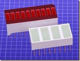
A bar display is a row of small rectangular LEDs in a single component. It may be used for digital representation of an analog signal. The higher the voltage of the signal, the more bars will be illuminated. A typical application would be to show the signal strength of an input to an audio recorder. Ten bars are often used, as in the display shown in Figure 24-10, but multiple components can be combined end to end.

clip_image024

Figure 24-10. Two LED bar displays in which segments can be lit individually.

Single Light Bar

A light bar can be thought of as a single-source LED, as it is configured as a single square or rec- tangle. It is mentioned here, rather than in the entry for single-source LED indicators, because variants may be subdivided into two, three, four, or (sometimes) more discrete sections. These variants are often included in the same datasheet as the monolithic version.

A light bar contains multiple LEDs (often, four in number) behind a translucent panel that pro- vides evenly diffused radiance.

Values

The values for most LED displays are basically the same as for LED indicators, in terms of color, brightness, current consumption, and voltage. See “Values” on page 211 for information.

Multiple-character dot-matrix LED display modules may have different requirements for forward voltage and forward current, depending on drivers that are incorporated in the module. Because there is no standardization for these modules, it will be necessary to consult the manufacturer’s datasheet.

How to Use It
Seven-Segment Basics

The diodes in a seven-segment LED display share either a common anode or a common cathode, the latter being more frequently used. The two types of internal wiring are provided for convenience only. Externally, the displays function identically.

A schematic suggesting the internal wiring and pinouts of a typical ten-pin common-cathode display is shown in Figure 24-11. The pins are numbered as seen from above. Appended to each number is the identity of the segment to which it is connected. Pins 3 and 8 are connected with the cathodes of all the internal LEDs. Both of these pins should be used, to serve as heat sinks for the display.

Note that series resistors are not included inside the display and must be added externally. Their value will be determined by the power supply, to limit the forward current and forward voltage through the LEDs to the extent specified by the manufacturer.

An encapsulated resistor array containing either seven or eight resistors in an SIP or DIP chip can be used instead of individual resistors. A seven- segment LED display would require the type of resistor array in which both ends of each resistor are accessible.

Where two or more numerals are combined in a single component, this type of display is likely to have two horizontal lines of pins. In this case, pin 1 will be at the bottom-left corner, seen from above. As always, the pins are numbered counterclockwise, seen from above.

clip_image027

Figure 24-11. A schematic view of internal connections and pinouts of a seven-segment common-cathode LED display. The numbers refer to the pins of the component, seen from above. The 1 pin may also have a mark beside it on the component, for identification. The orientation of the display can be deduced if there is a decimal point, as this should be at the bottom-right corner.

Where three or more numerals are combined in a single component, the pinouts may be de- signed for multiplexing rather than individual access to every segment of each numeral. A four- digit clock display, for instance, may have seven pins that connect in parallel to respective segments in all of the numerals, and four additional pins that can ground each numeral in turn, so that they can be selected sequentially.

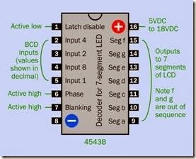
Driver Chips and Multiplexing Illuminating the appropriate segments in a single numeral can be done directly from a micro- controller, or through a driver chip such as the well-known and widely used 4543B that converts a binary-coded decimal input into appropriate segment output patterns. The chip can source sufficient current to drive each segment through a series resistor. Its pinouts are shown at Figure 24-12.

clip_image029

Figure 24-12. Pinouts of the 4543B seven-segment LED driver chip.

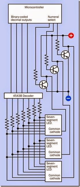
When used in conjunction with a microcontroller, the 4543B can drive several seven-segment displays by multiplexing them. The basic schematic to achieve this is shown in Figure 24-13, omitting optional features such as leading-zero blanking or connections for a decimal point. The microcontroller sends the binary code for the first numeral and simultaneously grounds the common cathode of that numeral through a transistor, which is needed because as many as seven segments of the numeral may be passing current in parallel. The microcontroller then sends the binary code for the second numeral, and grounds it; then sends the binary code for the third numeral, and grounds it; and the cycle repeats. So long as this process is performed at sufficient speed (at least 50Hz), persistence of vision will create the illusion that all the numerals are active simultaneously. The circuit can be compared with a similar circuit to drive LCDs, shown in Figure 17-17.

clip_image031

Figure 24-13. A basic, simplified circuit for driving multiple seven-segment LED displays by multiplexing them.

The disadvantage of this system is that the microcontroller must update the numerals con- stantly while performing other duties. To reduce this burden, a “smarter” driver such as the MC14489 can be used, controlling up to five 7- segment digits, or the Intersil ICM7218, which can control up to eight 7-segment digits.

The MC14489 controller receives data serially, using SPI protocol, and handles the details of ad- dressing the LEDs. Because it contains latches to sustain the displayed data, a microcontroller only needs to communicate with the driver when the displayed information needs to be updated.

The ICM7218 is a more sophisticated chip, avail- able in several variants, one of which can receive data on an 8-bit bus and run the seven-segment displays in hexadecimal mode.

Sixteen-Segment Driver Chip

The MAX6954 by Maxim can drive up to eight 16- segment alphanumeric LED displays using a scheme known as Charlieplexing, named after a Maxim employee named Charlie Allen who came up with the concept as a way of reducing the pin count required for multiplexing. Other Maxim controllers use this same protocol, which is trans- parent to the user.

A microcontroller sends data serially via I2C protocol to the MAX6954, which contains a variety of features. It can drive 14-segment and 7- segment displays as well as 16-segment displays, and contains a 104-character alphabet for each of them. Setting up a microcontroller to send the various necessary command codes to the MAX6954 is not a trivial matter, and bearing in mind the probably impending end-of-life of 16- segment displays, a better option may be to use dot-matrix LED display modules that have con- troller logic built in.

Dot-Matrix LED Display Modules

A dot-matrix LED display module requires data to define a character set, and a command interpreter to process instructions that will be embedded in a serial data stream. These capabilities are provided either by separate chips or (more often) are incorporated into the LED display module itself.

The SSD1306 is a monochrome graphical controller capable of I2C or SPI serial communication, or parallel communication. When this capability is built into a display module, only one of these types of communication may be activated.

The SSD1331 is a color graphical controller with similar communication capabilities.

The WS0010 is a monochrome controller, compatible with HD44780, which is designed to con- trol LCDs.

Typical controller functions are summarized in “Alphanumeric Display Module” on page 168. Because there is no standardization in this field, precise details must be found in manufacturers’ datasheets.

Pixel Arrays

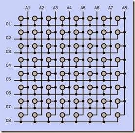
The connections inside an 8×8 pixel array are shown in Figure 24-14, where the schematic symbols for LEDs have been replaced by gray circles for space reasons. To illuminate one LED, power is supplied to the intersection where it resides. In the figure, each vertical conductor (identified as A1, A2 . . . A8) can power the anodes of a column of eight LEDs, while each horizontal conductor (identified as C1, C2 . . . C8) can ground the cath- odes of a row of eight LEDs. If only one vertical conductor is connected with positive power while one horizontal conductor is grounded, only one LED will light up, at the intersection of the active conductors.

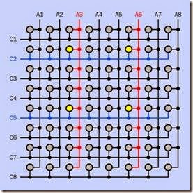
A problem occurs if we wish to illuminate two LEDs. Suppose they are located at (A3,C2) and (A6,C5). Unfortunately, providing power to them will also result in activating LEDs at (A3,C5) and (A6,C2), as shown in Figure 24-15, where the yellow circles represent LEDs that have been switched on.

The answer to this problem is to rasterize the process. In other words, data is supplied on the array one line at a time, as in the process by which a TV picture is generated. If this is done quickly enough, persistence of vision will create the

illusion that the LEDs are illuminated simultaneously.

clip_image033

Figure 24-14. Internal connections in the 8×8 matrix. Each gray circle represents an LED.

clip_image035

Figure 24-15. An attempt to illuminate LEDs at (A3,C2) and (A6,C5) will also activate the LEDs at (A3,C5) and (A6,C2).

A form of multiplexing is used to achieve this. One row of LEDs is connected to negative ground for a brief interval. During this interval, the anodes of selected LEDs are powered momentarily. Then the next row is grounded, and selected LEDs along that row are powered momentarily. This process is repeated for all eight rows before being repeated.

If several 8×8 matrices are assembled edge to edge, their horizontal conductors can be common to all of them. A horizontally scrollable dis- play (sometimes referred to by the archaic term, electric newspaper) would then be possible, al- though the circuit design would be nontrivial.

Multiple Bar Display Driver

The LM3914 is a driver for a bar display that com- pares an analog input with a reference voltage and provides power to the segments of a multiple bar display, ranging from 2mA to 30mA, adjustable to match the specification of the display that is being used. The chip can generate either a “thermometer” effect, as more outputs are activated when the analog input increases, or a “moving dot” effect, in which only one output is on at a time.

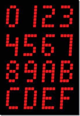
One-Digit Hexadecimal Dot Matrix While multi-character dot-matrix LED display modules are a versatile way to display prompts and numbers, a simpler component is some-times sufficient. The Texas Instruments TIL311 is a minimal dot-matrix LED display that receives a binary value from 0000 through 1111 on its four input pins and generates the output in hexadecimal form, using numerals 0 through 9 and letters A through F. The sixteen possible outputs in the dot-matrix display are shown in Figure 24-16. Al- though this component is no longer being manufactured, it is widely available from many sources, especially in Asia. It eliminates the series resistors and controller chip that are customary for a seven-segment display, and has a better- looking output.

clip_image037

Figure 24-16. Sixteen possible outputs that can be dis- played by the Texas Instruments TIL311 to show a hexadecimal value in response to a four-digit binary input.

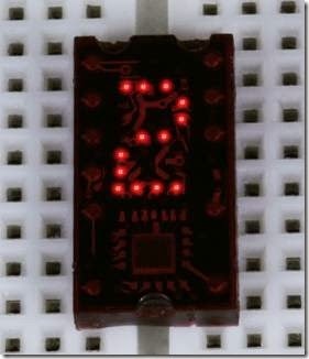
A sample of the TIL311 is shown in Figure 24-17 displaying the number 2.

If two or more of these chips are put together, they can be multiplexed to display multi-digit decimal or hexadecimal integers.

The chip features two decimal points, one to the left of the displayed numeral, and one to the right. If they are activated, they require their own series resistors to limit the current.

clip_image039

Figure 24-17. The Texas Instruments TIL311 can be driven directly by a microcontroller or counter chip, with no series resistors necessary. It can generate a hexadecimal output.

What Can Go Wrong
Common Anode versus Common Cathode

An LED display containing a common cathode is usually identical in appearance to a display containing a common anode, and the two versions will be distinguished by only one digit or letter in their part numbers. Because LED displays have a limited tolerance for reverse voltage, part numbers should be double-checked before applying power.

Incorrect Series Resistance

A common error is to assume that only one series resistor is necessary for a seven-segment LED display, either between the common cathode pin and ground, or, if there is a common anode, between that and the positive power supply. The problem is that if the resistor is suitable for a single LED, its value will be too high when several segments of the display are sinking current or drawing current through it. If its value is reduced, it will be too low when only two segments are using it (as when generating the number 1).

To provide equal illumination of all the segments, each must have its own series resistor.

Multiplexing Issues

When several displays are multiplexed, they naturally appear dimmer, creating a temptation to compensate by upping the current. Because cur- rent is only being applied to each display intermittently, a natural assumption is that a higher current can be safely used.

This may or may not be true. When running an LED device with pulsed current, the peak junction temperature, not the average junction temperature, determines the performance. At re- fresh rates below 1kHz, the peak junction temperature is higher than the average junction temperature, and the average current must therefore be reduced.

Datasheets must be checked to determine whether a device is designed with multiplexing in mind and, if so, what the recommended peak current is. Very often this value will be accompanied by a maximum duration in milliseconds, and a calculation may be necessary to determine the refresh rate, bearing in mind how many other LED displays are being multiplexed in the same circuit at the same time.

Irresponsible multiplexing will shorten the life of an LED display or burn it out.


vacuum-fluorescent display:What It Does,How It Works,Anode, Cathode, and Grid,How to Use It,Modern Application,Variants,Color,Character Sets and Pictorial Design,Comparisons,What Can Go Wrong and Fading.

vacuum-fluorescent display

The term vacuum-fluorescent display is seldom hyphenated, but the first two words are hyphenated here as they constitute an adjectival phrase. The acronym VFD is be- coming increasingly popular, although it is ambiguous, being also used to identify a variable frequency drive. In both instances, the acronym is printed without periods be- tween the letters.

The entry in this encyclopedia dealing with fluorescent lights does not include VFDs, because their purpose and design are very different. A VFD is an informational display, often showing numerals and letters, while a fluorescent light merely illuminates a room or work area. Although a VFD does use fluorescent phosphors, they are printed onto light-emitting segments of the display instead of being applied to the inside surfaces of a glass envelope.

What It Does

A vacuum-fluorescent display or VFD superficially resembles a backlit monochrome LCD or an LED display, as it can represent alphanumeric characters by using segments or a dot matrix, and can also display simple shapes. It is often brighter than the other information display systems, and can emit an intense green phosphorescent glow that some people find aesthetically pleasing, even though a grid of very fine wires is superimposed internally over the displayed image.

There is no specific schematic symbol to represent a vacuum-fluorescent display.

How It Works

The display is mounted inside a sealed capsule containing a high vacuum. A widely spaced series of very fine wires, primarily made of tungsten, functions as a cathode, moderately heated to en- courage electron emission. The wires are often referred to as filaments.

A fluorescent light uses AC, and both of its electrodes are often confusingly referred to as cathodes. A VFD uses DC, and its cathode array has the function that one would expect, being connected with the negative side of the DC power supply.

Opposite the cathode, just a few millimeters away, is an anode that is subdivided into visible alphanumeric segments, symbols, or dots in a matrix. Each segment of the anode is coated with phosphors, and individual segments can be separately energized via a substrate. When electrons strike a positively charged anode segment, it emits visible light in a process of fluorescence. This behavior can be compared with that of a cathode-ray tube. However, the cathodes in a VFD are efficient electron emitters at a relatively low temperature, while the cathodes in a cathode- ray tube require substantial heaters.

Anode, Cathode, and Grid

A grid consisting of a mesh of very fine wires is mounted in the thin gap between the filaments of the cathode and the segments of the anode. A simplified view of this arrangement is shown in Figure 25-1.

clip_image006

Figure 25-1. The basic elements of a vacuum-fluorescent display.

The polarity of the charge on the grid controls and diffuses electrons emitted by the cathode. If a grid section is negatively charged, it repels electrons and prevents them from reaching the

sections of the anode beneath it. If the grid section is positively charged, it encourages electrons to reach the anode. Thus, the grid functions in the same way as the grid in a triode vacuum tube, but its conductors are so thin, they are barely visible.

How to Use It

Electronic calculators used vacuum-fluorescent displays during the 1970s, before LED displays and LCDs became more competitive. Purely nu- meric VFD modules are still available as strings of digits, although they are becoming uncommon and have been replaced by alphanumeric dot- matrix modules where each VFD character is mounted in its own glass module on a separate substrate.

Figure 25-2 shows the interior of a Commodore calculator from the 1970s, with its nine-digit vacuum-fluorescent display enclosed in one glass capsule.

clip_image009

Figure 25-2. The vacuum-fluorescent display from a 1970s Commodore calculator.

A closeup of three digits from the previous figure appears in Figure 25-3, showing the grid super- imposed above each numeral.

clip_image011

Figure 25-3. Three digits from the previous figure, showing the grid that controls their illumination.

A tinted filter of the same color as the display is usually placed in front of it, to conceal some of its workings. Thus, the Commodore calculator used a green filter in front of its green numerals. Figure 25-4 shows two seven-segment numerals from another device, with the filter removed. This reveals not only the grid but also the horizontal wires that function as the cathode. Connections between the segments of the numerals and a backplane are also visible.

clip_image013

Figure 25-4. Seven-segment numerals viewed without a colored filter, revealing the cathode (horizontal wires) and the grid (wire mesh).

Modern Application

A modern VFD module is likely to be mated with a driver that converts 5VDC to the higher voltage (typically 50VDC to 60VDC) required for the dis- play. Built-in logic may offer the option to receive data via an 8-bit parallel bus or with SPI serial protocol, and will contain a character set. A typical display resolution is 128 x 64 pixels.

The combination of a grid and a segmented anode enables a VFD to be controlled by multiplexing. For instance, in a display of four seven- segment numerals, the same equivalent segments in all four numerals can be connected in parallel while a separate grid covers each numeral. When each grid is positively energized, it se- lects the corresponding numeral, and the on-off segment patterns appropriate to that numeral are supplied. This procedure is repeated for each numeral in turn. Persistence of vision makes it appear that they are all active simultaneously.

Variants
Color

Although a VFD cannot provide a full-color display, selected anode segments can be coated with different phosphor colors, which can fluoresce simultaneously. Two or three individual colors are typically used, as in the display for a CD player where color helps to distinguish a variety of different functions. A closeup of a portion of the display from a CD player (with color filter re- moved) appears in Figure 25-5.

clip_image016

Figure 25-5. The lefthand section of a vacuum- fluorescent display from a CD player.

Character Sets and Pictorial Design

In the past, VFDs have combined seven-segment numerals in the same display as custom-shaped anodes. Solid-state gain meters in an audio amplifier, for instance, have used numerals beside a pictorial representation of gain levels resembling analog meters. The look and layout of a display of this type has been unique to a particular product.

Modern VFDs tend to use a generic dot-matrix display in which a character set in firmware dic-tates how patterns of dots are grouped to form numbers, letters, symbols, or icons.

The appearance of character sets generated with generic segments and dot-matrix arrays is thoroughly discussed and illustrated in the entry de- scribing liquid-crystal displays in Chapter 17. VFD alphanumeric modules are identical in vis- ual design to LCD modules, even though the internal electronics are different.

Comparisons

Two advantages of a VFD are that it functions well at low temperatures (unlike an LCD) and has sufficient brightness and contrast to be usable in sunlight (unlike many LED displays). It can be viewed from almost any angle.

Typical applications have included digital instrumentation in automobiles, information displays in audio and video consumer-electronics equipment, and numerical readouts in vending ma- chines, medical devices, and some digital clocks.

Because a VFD requires a relatively high voltage, has significant power consumption, can show only a limited range of fixed colors, and is more expensive than LED displays or LCDs, its popularity has declined since the end of the 1990s.

What Can Go Wrong
Fading

VFDs gradually fade with age, as a result of reduced electron emission from the electrodes or diminishing performance of the phosphor coatings. Increasing the working voltage can prolong the life of a display.