Atomic Structure of Matter

Elements

There are a very large number of different substances in existence, each sub- stance containing one or more of a number of basic materials called elements. ‘An element is a substance which cannot be separated into anything simpler by chemical means’. There are 92 naturally occurring elements and 13 others, which have been artificially produced.

Some examples of common elements with their symbols are: Hydrogen H, Helium He, Carbon C, Nitrogen N, Oxygen O, Sodium Na, Magnesium Mg, Aluminium Al, Silicon Si, Phosphorus P, Sulphur S, Potassium K, Calcium Ca, Iron Fe, Nickel Ni, Copper Cu, Zinc Zn, Silver Ag, Tin Sn, Gold Au, Mercury Hg, Lead Pb and Uranium U.

Atoms

Elements are made up of very small parts called atoms. ‘An atom is the smallest part of an element which can take part in a chemical change and which retains the properties of the element’.

Each of the elements has a unique type of atom.

In atomic theory, a model of an atom can be regarded as a miniature solar system. It consists of a central nucleus around which negatively charged particles called electrons orbit in certain fixed bands called shells. The nucleus contains positively charged particles called protons and particles having no electrical charge called neutrons.

An electron has a very small mass compared with protons and neutrons. An atom is electrically neutral, containing the same number of protons as electrons. The number of protons in an atom is called the atomic number of the element of which the atom is part. The arrangement of the elements in order of their atomic number is known as the periodic table.

The simplest atom is hydrogen, which has 1 electron orbiting the nucleus and 1 proton in the nucleus. The atomic number of hydrogen is thus 1. The hydrogen atom is shown diagrammatically in Figure 4.1(a). Helium has 2 electrons orbiting the nucleus, both of then occupying the same shell at the same distance from the nucleus, as shown in Figure 4.1(b).

image

The first shell of an atom can have up to 2 electrons only, the second shell can have up to 8 electrons only and the third shell up to 18 electrons only. Thus an aluminium atom which has 13 electrons orbiting the nucleus is arranged as shown in Figure 1(c).

Molecules

When elements combine together, the atoms join to form a basic unit of new substance. This independent group of atoms bonded together is called a molecule. ‘A molecule is the smallest part of a substance which can have a separate stable existence’.

All molecules of the same substance are identical. Atoms and molecules are the basic building blocks from which matter is constructed.

Compounds

When elements combine chemically their atoms interlink to form molecules of a new substance called a compound. ‘A compound is a new substance containing two or more elements chemically combined so that their properties are changed’.

For example, the elements hydrogen and oxygen are quite unlike water, which is the compound they produce when chemically combined.

The components of a compound are in fixed proportion and are difficult to separate. Examples include:

(i) water H2O, where 1 molecule is formed by 2 hydrogen atoms combining with 1 oxygen atom,

(ii) carbon dioxide CO2 , where 1 molecule is formed by 1 carbon atom combining with 2 oxygen atoms,

(iii) sodium chloride NaCl (common salt), where 1 molecule is formed by 1 sodium atom combining with 1 chlorine atom, and

(iv) copper sulphate CuSO4 , where 1 molecule is formed by 1 copper atom, 1 sulphur atom and 4 oxygen atoms combining.

Mixtures

‘A mixture is a combination of substances which are not chemically joined together’. Mixtures have the same properties as their components. Also, the components of a mixture have no fixed proportion and are easy to separate. Examples include:

(i) oil and water

(ii) sugar and salt

(iii) air, which is a mixture of oxygen, nitrogen, carbon dioxide and other gases

(iv) iron and sulphur

(v) sand and water

Mortar is an example of a mixture — consisting of lime, sand and water.

Compounds can be distinguished from mixtures in the following ways:

(i) The properties of a compound are different to its constituent components whereas a mixture has the same properties as it constituent components.

(ii) The components of a compound are in fixed proportion whereas the components of a mixture have no fixed proportion.

(iii) The atoms of a compound are joined, whereas the atoms of a mixture are

free.

(iv) When a compound is formed, heat energy is produced or absorbed whereas when a mixture is formed little or no heat is produced or absorbed.

Solutions

‘A solution is a mixture in which other substances are dissolved’.

A solution is a mixture from which the two constituents may not be separated by leaving it to stand, or by filtration. For example, sugar dissolves in tea, salt dissolves in water and copper sulphate crystals dissolve in water leaving it a clear blue colour. The substance that is dissolved, which may be solid, liquid or gas, is called the solute, and the liquid in which it dissolves is called the solvent. Hence solvent Y solute = solution.

A solution has a clear appearance and remains unchanged with time.

Suspensions

‘A suspension is a mixture of a liquid and particles of a solid which do not dissolve in the liquid’.

The solid may be separated from the liquid by leaving the suspension to stand, or by filtration. Examples include:

(i) sand in water

(ii) chalk in water

(iii) petrol and water

Solubility

If a material dissolves in a liquid the material is said to be soluble. For example, sugar and salt are both soluble in water.

If, at a particular temperature, sugar is continually added to water and the mixture stirred there comes a point when no more sugar can dissolve. Such a solution is called saturated. ‘A solution is saturated if no more solute can be made to dissolve, with the temperature remaining constant’.

Solubility is a measure of the maximum amount of a solute which can be dissolved in 0.1 kg of a solvent, at a given temperature’. For example, the solubility of potassium chloride at 20°C is 34 g per 0.1 kg of water, or, its percentage solubility is 34%

(i) Solubility is dependent on temperature. When solids dissolve in liquids, as the temperature is increased, in most cases the amount of solid that will go into solution also increases. (More sugar is dissolved in a cup of hot tea than in the same amount of cold water.) There are exceptions to this, for the solubility of common salt in water remains almost constant and the solubility of calcium hydroxide decreases as the temperature increases.

(ii) Solubility is obtained more quickly when small particles of a substance are added to a liquid than when the same amount is added in large particles. For example, sugar lumps take longer to dissolve in tea than does granulated sugar.

(iii) A solid dissolves in a liquid more quickly if the mixture is stirred or shaken, i.e. solubility depends on the speed of agitation.

Crystals

A crystal is a regular, orderly arrangement of atoms or molecules forming a distinct pattern, i.e. an orderly packing of basic building blocks of matter. Most solids are crystalline in form and these include crystals such as common salt and sugar as well as the metals. Substances that are non-crystalline, are called amorphous, examples including glass and wood. Crystallisation is the process of isolating solids from solution in a crystalline form. This may be carried out by adding a solute to a solvent until saturation is reached, raising the temperature, adding more solute and repeating the process until a fairly strong solution is obtained, and then allowing the solution to cool, when crystals will separate. There are several examples of crystalline form that occur naturally, examples including graphite, quartz, diamond and common salt.

Crystals can vary in size but always have a regular geometric shape with flat faces, straight edges and having specific angles between the sides. Two common shapes of crystals are shown in Figure 4.2. The angles between the faces of the common salt crystal (Figure 4.2(a)) are always 90° and those of a quartz crystal (Figure 2(b)) are always 60° . A particular material always produces exactly the same shape of crystal.

image

image

Figure 4.3 shows a crystal lattice of sodium chloride. This is always a cubic shaped crystal being made up of 4 sodium atoms and 4 chlorine atoms. The sodium chloride crystals then join together as shown.

Metals

Metals are polycrystalline substances. This means that they are made up of a large number of crystals joined at the boundaries, the greater the number of boundaries the stronger the material.

Every metal, in the solid state, has its own crystal structure. To form an alloy, different metals are mixed when molten, since in the molten state they do not have a crystal lattice. The molten solution is then left to cool and solidify. The solid formed is a mixture of different crystals and an alloy is thus referred to as a solid solution. Examples include:

(i) brass, which is a combination of copper and zinc,

(ii) steel, which is mainly a combination of iron and carbon,

(iii) bronze, which is a combination of copper and tin.

Alloys are produced to enhance the properties of the metal, such as greater strength. For example, when a small proportion of nickel (say, 2% Ð 4%) is added to iron the strength of the material is greatly increased. By controlling the percentage of nickel added, materials having different specifications may be produced.

A metal may be hardened by heating it to a high temperature then cooling it very quickly. This produces a large number of crystals and therefore many boundaries. The greater the number of crystal boundaries, the stronger is the metal.

A metal is annealed by heating it to a high temperature and then allowing it to cool very slowly. This causes larger crystals, thus less boundaries and hence a softer metal.


SI Units

Units

The system of units used in engineering and science is the Syste`me Internationale d’Unite´s (International system of units), usually abbreviated to SI units, and is based on the metric system. This was introduced in 1960 and is now adopted by the majority of countries as the official system of measurement.

The basic units in the S.I. system are listed below with their symbols:

image

Prefixes

S.I. units may be made larger or smaller by using prefixes that denote multi- plication or division by a particular amount. The six most common multiples, with their meaning, are listed below:

image

Length, area, volume and mass

Length is the distance between two points. The standard unit of length is the metre, although the centimetre, cm, millimetre, mm and kilometre, km, are often used.

1 cm D 10 mm, 1 m D 100 cm D 1 000 mm and 1 km D 1 000 m

Area is a measure of the size or extent of a plane surface and is measured by multiplying a length by a length. If the lengths are in metres then the unit of area is the square metre, m2

image

Conversely, 1 cm2 D 10ð4 m2 and 1 mm2 D 10ð6 m2

Volume is a measure of the space occupied by a solid and is measured by multiplying a length by a length by a length. If the lengths are in metres then the unit of volume is in cubic metres, m3

image

Derived SI Units

Derived SI units use combinations of basic units and there are many of them. Two examples are:

Velocity – metres per second (m/s)

Acceleration – metres per second squared (m/s2 )

Charge

The unit of charge is the coulomb (C) where one coulomb is one ampere second. (1 coulomb D 6.24 ð 1018 electrons). The coulomb is defined as the quantity of electricity which flows past a given point in an electric circuit when a current of one ampere is maintained for one second. Thus,

image

where I is the current in amperes and t is the time in seconds.

Force

The unit of force is the newton (N) where one newton is one kilogram metre per second squared. The newton is defined as the force which, when applied to a mass of one kilogram, gives it an acceleration of one metre per second squared. Thus,

image

where m is the mass in kilograms and a is the acceleration in metres per second squared. Gravitational force, or weight, is mg, where g D 9.81 m/s2

Work

The unit of work or energy is the joule (J) where one joule is one newton metre. The joule is defined as the work done or energy transferred when a force of one newton is exerted through a distance of one metre in the direction of the force. Thus

image

where F is the force in newtons and s is the distance in metres moved by the body in the direction of the force. Energy is the capacity for doing work.

Power

The unit of power is the watt (W) where one watt is one joule per second. Power is defined as the rate of doing work or transferring energy. Thus,

image

Electrical potential and e.m.f.

The unit of electric potential is the volt (V), where one volt is one joule per coulomb. One volt is defined as the difference in potential between two points in a conductor which, when carrying a current of one ampere, dissipates a power of one watt, i.e.

image

A change in electric potential between two points in an electric circuit is called a potential difference. The electromotive force (e.m.f.) provided by a source of energy such as a battery or a generator is measured in volts.


Scalars and Vectors

Scalars and Vectors

Quantities used in engineering and science can be divided into two groups:

(a) Scalar quantities have a size (or magnitude) only and need no other information to specify them. Thus, 10 centimetres, 50 seconds, 7 litres, 3 kilograms, 25°C, £250, 10 cm3 volume and 10 joules of energy, are all examples of scalar quantities.

(b) Vector quantities have both a size or magnitude and a direction, called the line of action of the quantity. Thus, a velocity of 50 kilometers per hour due east, an acceleration of 9.81 meters per second squared vertically downwards, a force of 15 newtons at an angle of 30 degrees, and a north- westerly wind of 15 knots are all examples of vector quantities.

The speed of a body can be stated without reference to the direction of movement of that body. Thus, speed is a scalar quantity. If, however, we specify the direction of motion as well as the speed of the body, the quantity is then termed the velocity of the body. Velocity is thus a vector quantity.

A weight of, say, 20 newtons, might initially appear to be a scalar quantity; however, weight also has a direction, i.e. downwards (towards the center of the earth). Thus, weight is a vector quantity.

When we say a man has walked 7 km we give no indication of direction. Thus, distance is a scalar quantity. If, however, the man walks 4 km westwards, then 3 km northwards as shown in Figure 3.1, his final position at C is 5 km away from his initial position at A (by Pythagoras’ theorem). This change in position is called displacement. Thus 7 km is the distance walked, and 5 km in a direction N37°W is a vector quantity.

Summarising, a quantity that has magnitude and direction is a vector quantity, whereas a quantity that has magnitude only is a scalar quantity.

Vector Representation

A vector may be represented by a straight line, the length of line being directly proportional to the magnitude of the quantity and the direction of the line being

image

in the same direction as the line of action of the quantity. An arrow is used to denote the sense of the vector, that is, for a horizontal vector, say, whether it acts from left to right or vice-versa. The arrow is positioned at the end of the vector and this position is called the ‘nose’ of the vector. Figure 3.2 shows a velocity of 20 m/s at an angle of 45° to the horizontal and may be depicted by oa D 20 m/s at 45° to the horizontal.

To distinguish between vector and scalar quantities, various ways are used. These include:

(i) bold print,

(ii) two capital letters with an arrow above them to denote the sense of direc- tion, e.g. ðA!B, where A is the starting point and B the end point of the vector,

(iii) a line over the top of letters, e.g. AB or a

(iv) letters with an arrow above, e.g. aE, AE

(v) underlined letters, e.g. a

(vi) xi C jy, where i and j are axes at right-angles to each other; for example, 3i C 4j means 3 units in the i direction and 4 units in the j direction, as shown in Figure 3.3

(vii) a column matrix ( a b); for example, the vector OA shown in Figure 3.3could be represented by ( 3 4)

image

Thus, OA represents a vector quantity, but OA is the magnitude of the vector OA. Also, positive angles are measured in an anticlockwise direction from a horizontal, right facing line, and negative angles in a clockwise direction from this line — as with graphical work. Thus 90° is a line vertically upwards and ð90° is a line vertically downwards.

image


Scalars and Vectors

Scalars and Vectors

Quantities used in engineering and science can be divided into two groups:

(a) Scalar quantities have a size (or magnitude) only and need no other information to specify them. Thus, 10 centimetres, 50 seconds, 7 litres, 3 kilograms, 25°C, £250, 10 cm3 volume and 10 joules of energy, are all examples of scalar quantities.

(b) Vector quantities have both a size or magnitude and a direction, called the line of action of the quantity. Thus, a velocity of 50 kilometers per hour due east, an acceleration of 9.81 meters per second squared vertically downwards, a force of 15 newtons at an angle of 30 degrees, and a north- westerly wind of 15 knots are all examples of vector quantities.

The speed of a body can be stated without reference to the direction of movement of that body. Thus, speed is a scalar quantity. If, however, we specify the direction of motion as well as the speed of the body, the quantity is then termed the velocity of the body. Velocity is thus a vector quantity.

A weight of, say, 20 newtons, might initially appear to be a scalar quantity; however, weight also has a direction, i.e. downwards (towards the center of the earth). Thus, weight is a vector quantity.

When we say a man has walked 7 km we give no indication of direction. Thus, distance is a scalar quantity. If, however, the man walks 4 km westwards, then 3 km northwards as shown in Figure 3.1, his final position at C is 5 km away from his initial position at A (by Pythagoras’ theorem). This change in position is called displacement. Thus 7 km is the distance walked, and 5 km in a direction N37°W is a vector quantity.

Summarising, a quantity that has magnitude and direction is a vector quantity, whereas a quantity that has magnitude only is a scalar quantity.

Vector Representation

A vector may be represented by a straight line, the length of line being directly proportional to the magnitude of the quantity and the direction of the line being

image

in the same direction as the line of action of the quantity. An arrow is used to denote the sense of the vector, that is, for a horizontal vector, say, whether it acts from left to right or vice-versa. The arrow is positioned at the end of the vector and this position is called the ‘nose’ of the vector. Figure 3.2 shows a velocity of 20 m/s at an angle of 45° to the horizontal and may be depicted by oa D 20 m/s at 45° to the horizontal.

To distinguish between vector and scalar quantities, various ways are used. These include:

(i) bold print,

(ii) two capital letters with an arrow above them to denote the sense of direc- tion, e.g. ðA!B, where A is the starting point and B the end point of the vector,

(iii) a line over the top of letters, e.g. AB or a

(iv) letters with an arrow above, e.g. aE, AE

(v) underlined letters, e.g. a

(vi) xi C jy, where i and j are axes at right-angles to each other; for example, 3i C 4j means 3 units in the i direction and 4 units in the j direction, as shown in Figure 3.3

(vii) a column matrix ( a b); for example, the vector OA shown in Figure 3.3could be represented by ( 3 4)

image

Thus, OA represents a vector quantity, but OA is the magnitude of the vector OA. Also, positive angles are measured in an anticlockwise direction from a horizontal, right facing line, and negative angles in a clockwise direction from this line — as with graphical work. Thus 90° is a line vertically upwards and ð90° is a line vertically downwards.

image


Density

Density is the mass per unit volume of a substance. The symbol used for density is p (Greek letter rho) and its units are kg/m3

image

where m is the mass in kg, V is the volume in m3 and p is the density in kg/m3

Some typical values of densities include:

image

The relative density of a substance is the ratio of the density of the substance to the density of water, i.e.

image

Relative density has no units, since it is the ratio of two similar quantities. Typical values of relative densities can be determined from above (since water has a density of 1000 kg/m3), and include:

image

The relative density of a liquid may be measured using a hydrometer.

For example, the relative density of a piece of steel of density 7850 kg/m3 , given that the density of water is 1000 kg/m3 , is given by:

image


speaker:What It Does,How It Works,Construction,Multiple Drivers,Venting,Resonance,Miniature Speakers,Variants,Electrostatic Speaker,Powered Speakers and Wireless Speakers.

speaker

The term speaker is a diminution of loudspeaker. The full word is now so rarely used, some catalogs do not recognize it as a search term. This encyclopedia acknowledges contemporary usage by using speaker rather than loudspeaker.

A fully assembled consumer product can be referred to as a “speaker,” but it also contains one or more individual components that are described as “speakers.” To resolve this ambiguity, referring to the components as drivers is helpful, but this practice can create more ambiguity because other types of components are also called “drivers.” The only real guide to the meaning of speaker is the context in which it is used.

For the purposes of this entry, a speaker is a sound reproduction device, distinguished from a typical electromagnetic transducer by being larger and more powerful, with a more linear frequency response. A transducer may be used as a noise-creating device to provide an alert, informing the user of the status of a piece of equipment. Because some speakers have been miniaturized for use in handheld products, they may be used as transducers, allowing some overlap between the two categories.

Because this encyclopedia assigns more emphasis to electronic components than to consumer products, this entry provides only a superficial overview of fully assembled speakers, and deals more with the drivers inside them, their principles of operation, and the general topic of sound reproduction.

What It Does

A speaker converts fluctuations of an electric signal into pressure waves that the human ear per- ceives as sound. It can be used for entertainment purposes or to provide information in the form of spoken words or distinctive sounds (as in the case of a miniature speaker in a cellular phone, playing a ring tone).

The internationally accepted schematic symbol for a speaker is shown in Figure 30-1.

image

Figure 30-1. Only one symbol exists to represent a speaker. This is it.

How It Works

For a summary of basic concepts and terminology relating to sound and its reproduction, see “Audio Basics” on page 261 in the previous entry.

Construction

A speaker contains a diaphragm or cone with a coil attached to it. Fluctuations of current through the coil interact with a permanent mag- net, causing the speaker to emit pressure waves that are proportionate with the current. The de- sign is similar in concept to that of a headphone, shown diagrammatically in Figure 29-3. The primary difference is that a speaker of around 2” or more will use a cone rather than a flat diaphragm. The cone shape is more rigid and creates a more directional sound.

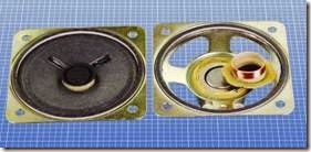
A 2” speaker rated for 1/4W with a 63Ω coil is shown in Figure 30-2, undamaged on the left but with its cone cut out on the right. The neck of the cone, which is normally inserted in the circular groove in the speaker magnet, is shown with the inductive coil wrapped around it.

clip_image008

Figure 30-2. On the left is a 2” speaker. On the right, its cone has been cut away to reveal the magnet, with a circular groove in it. The neck of the cone, which normally slides into the groove, is shown removed.

A speaker with a cone 4” in diameter is shown from the rear in Figure 30-3.

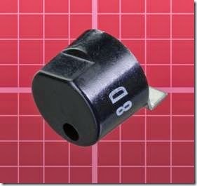
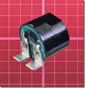
A miniature surface-mount speaker is shown from the front and from the rear in Figures 30-4 and 30-5. It measures just under 0.4” diameter and was made for Motorola. Its power rating is 50mW.

clip_image010

Figure 30-3. The back side of a speaker with a cone measuring approximately 4” in diameter. Its magnet is the large round section that is uppermost. This unit is rated for 4W and has an impedance of 8Ω.

A speaker designed for a cellular phone is shown in Figure 30-6. Note the close resemblance in de- sign to the driver used in an earbud, shown in Figure 29-6 in the previous entry.

In the past, speaker cones were made from tough, fibrous paper. Modern cones are more likely to be plastic, especially in small sizes.

clip_image012

Figure 30-4. Front view of a surface-mount speaker measuring less than 0.4” diameter.

clip_image014

Figure 30-5. Rear view of the speaker shown in the previous figure.

clip_image016

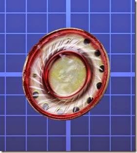
Figure 30-6. A miniature speaker measuring slightly more than 1/2” diameter and only 0.13” thick, designed for use in a cellular phone. It has an impedance of 150Ω.

Multiple Drivers

Generally speaking, a large-diameter speaker cone is more effective than a small cone at moving the greater volumes of air associated with re- production of bass notes. However, the inertia of a large cone impairs its ability to vibrate at high frequencies.

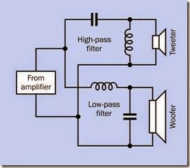
To address this problem, a large speaker and a small speaker often share a single enclosure. A crossover network using coils and capacitors pre- vents low frequencies from reaching the small speaker and high frequencies from reaching the large speaker. The basic principle is shown in the simplified schematic in Figure 30-7.

clip_image018

Figure 30-7. The basic principle of a crossover network.

Because the crossover network must be “tuned” to match the characteristics of the speakers, and because the combined sound pressure of the speakers must be relatively consistent over a wide range of frequencies, an actual network usually includes additional components.

Because the audio output from an amplifier consists of alternating current, polarized capacitors cannot be used. Polyester capacitors are common.

The small speaker in a pair is known as a tweeter while the large speaker is a woofer. Although these appellations were whimsically coined, they have endured.

More than two speakers may be combined in an enclosure, in a wide variety of configurations.

Venting

A speaker radiates pressure waves from the back side of its cone as well as from the front, and be- cause the waves from front and back are opposite in phase, they will tend to cancel each other out.

In a miniature speaker, this problem can be ad- dressed simply by sealing the section of the en- closure at the rear. For larger components, a more efficient enclosure can be designed with a vent or reflex port at the front. Pressure waves from the back of the speaker are diverted over a sufficient distance inside the cabinet so that by the time they emerge through the port, they are approximately in phase with low frequencies from the front of the speaker, although the back wave will lag the front wave by one wavelength.

This design is referred to as a bass-reflex enclosure, and was almost universal in high-fidelity components until amplifiers became increasing- ly powerful during the 1960s. At that point, Acoustic Research, located in Massachusetts, marketed a product line in which speaker enclosures were sealed, the argument being that when an amplifier can deliver 100W per channel, efficiency is no longer an issue, and a sealed en- closure can eliminate compromises associated with a bass-reflex design.

Acoustic Research referred to their concept as “air suspension,” as the cushion of air in the sealed cavity helped to protect the speaker by limiting its excursion. This configuration is now often referred to as a closed-box speaker. Some audiophiles argue that it must always be inherently superior to a bass-reflex design, partly because of the one-wavelength lag time associated with a reflex port. However, as in many aspects of sound reproduction, the debate is inconclusive.

Resonance

The enclosure for a speaker will tend to have a dominant resonant frequency. This should be lower than the lowest frequency that the speaker will reproduce; otherwise, the resonance will emphasize some frequencies relative to others, creating unwanted peaks in the response.

One reason why high-quality speakers tend to be physically heavy is to reduce their resonant frequency. A modern Thiel speaker assembly, for instance, uses a front panel of particle board that is a full 2” thick. However, heavy enclosures are expensive to transport and inconvenient to locate or relocate in the home.

To address this problem, a tweeter and a woofer can be mounted in separate boxes. The enclo- sure for the tweeter can be very small, light- weight, and suitable for placement on a shelf, while the heavy box for the woofer can go on the floor. Human senses have difficulty locating the source of low-frequency sound, so the woofer can be located almost anywhere in a room. In fact, its single speaker can serve both stereo channels.

This configuration has become the default for computer speakers. It is also used in home- theater systems, where the woofer has now be- come a subwoofer capable of very low frequency reproduction.

Miniature Speakers

If an electronics project has an audio output, and the circuit board will be sharing an enclosure with a small speaker, the size of the box and the material from which it is fabricated will affect the sound quality significantly. A box made from thin hardwood may add resonance that sounds pleasing, if the speaker is being used just for sim- ple electronic tones. By comparison, a metal box may sound “tinny.” A box fabricated from a plastic such as ABS will be relatively neutral, provided the plastic is reasonably thick (1/4” being preferable).

Variants
Electrostatic Speaker

The principle of an electrostatic speaker is the same as that of an electrostatic headphone. A charged membrane is stretched between two grids in front of it and behind it that act as electrodes. Because the membrane is so light, it responds with very little latency, and its large sur- face area creates a diffused sound that many audiophiles find pleasing. However, a high voltage is required to drive electrostatic speakers, and they are not cheap.

Powered Speakers

A unit containing its own driver electronics is referred to as a powered speaker, and is used almost universally with desktop computers, because the computer itself does not contain a power amplifier. Powered speakers may also enable a more versatile crossover network.

A subwoofer may have its own amplifier allowing control of the cutoff frequency above which the speaker will not attempt to reproduce sound. The electronics can include protection for a speaker against being overdriven.

Wireless Speakers

A wireless link between a stereo receiver and its speakers will eliminate the speaker wires that are normally necessary. However, the speakers themselves must be powered, and will have to be wired to electric outlets.

Innovative Designs

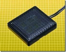
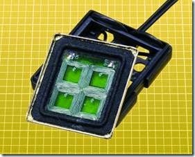
The need for small speakers in consumer products such as laptop computers has encouraged innovative designs. The speaker in Figure 30-8 is just 1” square, and its shape is easier to accommodate in a small product than the traditional circular speaker. In Figure 30-9, the interior of the same speaker shows that inductive coils are ap- plied to a square plastic diaphragm.

clip_image020

Figure 30-8. A speaker 1” square, suitable for use with a small electronic device.

clip_image022

Figure 30-9. The speaker from the previous figure, opened to show its inductive coils applied to a square plastic diaphragm.

Values

The typical impedance for speakers in audio systems is 8Ω. Small speakers may have a higher impedance, which can be useful when driving them from devices that have limited power, such as a TTL-type 555 timer.

In the United States, the diameter of a circular speaker is usually expressed in inches. Speakers larger than 12” are rare for domestic use. A 4” speaker used to be considered minimal because of its limited low-end frequency response, but much smaller speakers have become common in portable devices.

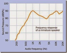
The low-end frequency response of a miniature loudspeaker designed to be surface-mounted on a circuit board will be very poor. The graph in Figure 30-10 was derived from data supplied by the manufacturer.

clip_image024

Figure 30-10. Frequency response for a speaker measuring 15mm x 15mm x 5mm. Small dimensions and lack of an enclosure result in a negligible low-end response.

Power rating for speakers is in watts, measured on a root-mean-square (RMS) basis.

Sensitivity is measured in decibels, at a distance of one meter, while a speaker is reproducing a single constant tone with a power input of 1W. A speaker assembly designed for undemanding home use may be rated at 85dB to 95dB.

Efficiency is a measure of sound power output divided by electrical power input. A value of 1% is typical.

What Can Go Wrong

Damage

As is the case with headphones, the most common problem affecting a speaker is damage caused by overdriving it. Because a low frequency requires larger excursions of a speaker cone to transmit an amount of energy comparable to that of a high frequency, loud bass notes can be hazardous to the cone. On the other hand, if an amplifier generates distortion (perhaps because it, too, is being overdriven), the harmonics cre- ated by the distortion can damage high- frequency speakers.

Magnetic Field

Even a small speaker (measuring 2” or less) con- tains a magnet that is sufficiently powerful to cause problems if it is in close proximity to other components, especially if sensors such as reed switches or Hall-effect switches are being used. Initial circuit testing should be done with the speaker as far away as possible, to eliminate it as a source of interference.

Vibration

Solder joints will be stressed if they are subjected to low-frequency vibration from a speaker. Loose parts may rattle, and parts that are bolted into place may become unbolted. The speaker itself may become loose. Thread-locker such as Loc- Tite should be applied to nuts before they are tightened.


headphone:What It Does,How It Works,Audio Basics,Variants,Mechanical Design,Values,Intensity,Frequency Response,Distortion and Impedance.

headphone

The term headphone is used here to include almost any device that fits into or over the ear for the purpose of sound reproduction. (Hearing aids are not included.) Because headphones are used in pairs, the term is usually pluralized.

The term phones is fairly common as a colloquial diminution of headphones but is not used here.

An earphone used to be a single sound reproduction device designed for insertion into the ear, but has become rare. Pairs of earbuds are now common.

Because this encyclopedia assigns more emphasis to electronic components than to consumer products, this entry provides only a superficial overview of fully assembled headphones, and deals more with the drivers inside them, their principles of operation, and the general topic of sound reproduction.

What It Does

A headphone converts fluctuations of an electric signal into pressure waves that the human ear perceives as sound. It can be used for reproduction of music for entertainment purposes, or for speech in telecommunications, broadcasting, and audio recording.

Two symbols for headphones are shown in Figure 29-1. The symbol on the left shows a single headphone or earphone; when this symbol is flipped horizontally, it can represent a micro- phone. The pictographic symbol on the right has been used for many decades, but is still often found in schematics.

image

Figure 29-1. Schematic symbols for a single earphone or headphone (left) and a pair of headphones (right).

How It Works
Audio Basics

Sound is transmitted as pressure waves through a medium that is usually air but can be a gas, fluid, or solid. The speed of transmission will vary with the density and other attributes of the medium. Small hairs in the inner ears, known as cilia, vibrate in sympathy with pressure waves and transmit nerve impulses to the brain, which interprets the impulses as sound.

Three quantities describe the propagation of any type of wave, including a sound wave: its frequency (customarily represented with letter f ), its speed of propagation (represented with letter v, for velocity), and its wavelength from peak-to- peak (represented by the Greek letter lambda, which appears as this λ symbol).

The relationship is defined by a very simple equation:

v = λ * f

Velocity is usually measured in meters per second, wavelength in meters, and frequency in Hertz, abbreviated Hz. One cycle per second is 1Hz. The H is always capitalized, as it refers to the name of Heinrich Rudolf Hertz, the first scientist to prove the existence of electromagnetic waves. One thousand Hertz can be written as 1 kilo- Hertz, almost always abbreviated as 1kHz (note that the k is lowercase).

The human ear is often described as being able to detect sounds between 20Hz and 20kHz, al- though the ability to hear sounds above 15kHz is relatively unusual and diminishes naturally with age. Sensitivity to all frequencies can be impaired by long-term exposure to loud noise.

Naturally occurring sounds can be converted to fluctuations in voltage by a microphone, which will be found listed as a sensor in Volume 3 of this encyclopedia. Artificial sounds can be generated as voltage fluctuations by oscillators and other electronic circuits. In either case, the output fluctuations can range between an upper limit set by a positive supply voltage and a lower limit established by electrical ground (which is assumed to be 0 volts). Alternatively, the fluctuations can range between the positive supply voltage and an equal and opposite negative supply voltage, with 0V lying midway between the two. This op- tion can be less convenient electrically but is a more direct representation of sound, because sound waves fluctuate above and below ambient air pressure, which can be considered analogous to a ground state.

The concept of positive and negative sound waves is illustrated in Figure 29-2 (originally published in the book Make: More Electronics).

clip_image008

Figure 29-2. The use of positive and negative voltages to represent a wave of high sound pressure followed by a trough of lower pressure.

The topic of sound amplification is explored in detail in the entry on op-amps in Chapter 7.

A headphone inverts the function of a micro- phone by converting electricity back into air- pressure waves. This is done electromagnetically (moving a diaphragm in response to an electro- magnet) or electrostatically (moving a membrane in response to electrostatic force between two charged electrodes).

Variants
Moving Coil

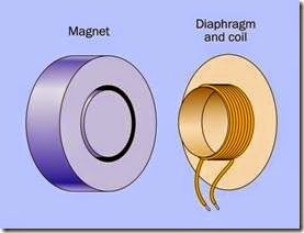
The most enduringly popular type of headphone uses a coil attached to a diaphragm. This is known as a moving-coil headphone, as the coil moves with the diaphragm. It can also be referred to as having a dynamic driver or dynamic transducer, “dynamic” referring to the movement of the coil.

The moving-coil concept is illustrated in Figure 29-3. The coil slides into a deep, narrow, circular slot in a magnet that is attached to the plastic frame of the headphone. The diaphragm is supported at its edges by a flexible rim. Variations in current passing through the coil create a fluctuating magnetic field that interacts with the field of the fixed magnet, causing the diaphragm to move in and out. A very similar configuration is used in many loudspeakers. Detail modifications may be made to increase efficiency, reduce production costs, or enhance sound quality, but the principle remains the same.

clip_image010

Figure 29-3. The basic elements of a moving-coil head- phone.

The internal element of a headphone is shown in Figure 29-4. A plastic diaphragm is visible, measuring slightly less than 2” in diameter. The mag- net and coil are concealed underneath.

The element in the previous figure is normally enclosed in an assembly such as the one in Figure 29-5, which incorporates a soft padded rim to rest upon the ear.

In an effort to achieve a more balanced frequency response, some designs use two moving-coil drivers in each headphone, optimized for low frequencies and high frequencies, respectively.

Earbuds, described after the next section, often use a miniaturized version of the moving-coil design.

clip_image012

Figure 29-4. The sound reproducing element removed from a headphone.

clip_image014

Figure 29-5. The sound reproducing element from the previous figure is normally packaged inside this enclosure.

Other Types

Electrostatic headphones use a thin, flat diaphragm suspended between two grids that function as electrodes. A fluctuating potential between the grids, coupled with a reverse-phase voltage on the diaphragm, will vibrate the diaphragm, generating pressure waves. A relatively high voltage is necessary to achieve this, any- where from 100V to 1,000V, supplied through a conversion unit between the headphones and an amplifier. Electrostatic headphones are known for low distortion and an excellent high frequency response, at some extra cost.

Electret headphones work on a similar principle, except that the membrane is permanently charged, and a high voltage is not required. Electret headphones tend to be small, inexpensive, and not of high sound quality.

A balanced armature design, often referred to by the acronym BA, uses a pivoting magnet that is claimed to increase efficiency while reducing stress on a diaphragm. BA drivers can be extremely compact, contained within a sealed met- al enclosure measuring less than 10mm x 10mm x 5mm. They are commonly used in conjunction with in-ear earphones, described in the next section.

Mechanical Design

Circumaural headphones use large soft pads to encircle the ear and block external noise. Their size tends to make them heavy, requiring a well- designed headband to provide comfortable sup- port. Supra-aural headphones are smaller and lighter, resting on the ears instead of enclosing them. They cannot exclude ambient noise, and may have inferior bass response compared with the circumaural type.

Open-back headphones, also known as acoustically transparent, are favored by some audiophiles because their vented outer surfaces are thought to create a more natural sound, similar to that of a speaker. The open backs naturally allow ambient noise to intrude, but also allow the sound generated by the headphones to be heard by others in a room. Closed-back headphones contain their sound and provide more insulation against ambient noise.

Earbuds rest just within the outer folds of the ear, facing inward like a pair of tiny speakers. They are easily dislodged and provide very little insulation against ambient noise. Their use became common after the introduction of Apple’s iPod. A pair of earbuds, one of them with its plastic cover removed, is shown in Figure 29-6.

clip_image016

Figure 29-6. A pair of earbuds, one with its cover re- moved to show the sound reproducing element, which closely resembles the diaphragm in a full-sized head- phone.

In-ear headphones are designed for insertion into the ear canal, often using a soft sheath that con- forms with the ear like an earplug. This sheath is disposable for hygienic reasons, and because it may lose some of its plasticity with use. It excludes most ambient noise, and by minimizing the air gap between the driver of the headphone and the ear drum enables a high quality of sound reproduction.

In-ear headphones are also known as in-ear monitors, IEMs, ear canal headphones, earphones, and canalphones. A pair of in-ear headphones is shown in Figure 29-7, one of them with its foam sheath removed. The rectangular silver-colored object in the headphone on the left contains a transducer to create sound pressure.

A headset consists of one or two headphones plus a flexible microphone that extends to the promiximity of the mouth of the user.

Noise-cancelling headphones, popularized by Bose, monitor external noise with a built-in microphone and generate sound of opposite phase, to provide some cancellation. They are particularly effective on jet aircraft, where back- ground noise tends to be consistent.

clip_image018

Figure 29-7. A pair of in-ear headphones, supplied with disposable foam plugs that conform flexibly with the ear canal. The headphone on the left is shown with its plug re- moved.

Although an earphone is almost obsolete, it is still obtainable from specialty suppliers. It has a high impedance, making it suitable for use with a crystal-set radio. An earphone is pictured in Figure 29-8.

clip_image020

Figure 29-8. A vintage earphone of the type suitable for use with a crystal-set radio.

Values
Intensity

Sound pressure is measured in decibels. For a complete explanation and discussion of weigh- ted and unweighted decibel scales, see “Sound Pressure” on page 251 in the transducer entry.

Frequency Response

A plot of sound pressure as a function of frequency shows the frequency response of a head- phone. Measuring the sound pressure meaning- fully is a challenge, because the ear canal will add coloration to the sound and can amplify some frequencies while masking others. Ideally, measurement should be done at the ear drum, but this is not feasible. Consequently, high-end head- phones are evaluated by making sound measurements inside simulated ear canals in a dummy human head.

A comparison between a high-quality $500 audio product and a transducer that is sold as a component for less than $1 illustrates the difference in frequency response; see Figure 29-9. The Sennheiser headphones have a smooth response that rises toward the low end, compensating for the lack of bass response that tends to be a problem in headphones, and the relative in- sensitivity of the human ear to low frequencies. The fluctuations at the high end are within about 5dB.

By comparison, the Kobitone emphasizes the range between 3kHz and 4kHz because its primary task is to be heard, and these are the frequencies where human hearing is most sensitive. Its low-frequency response trails off (although is still much better than that of a piezoelectric transducer, where the low response typically diminishes by 40dB to 50dB). The low-frequency output of the Kobitone is actually impressive bearing in mind that the component is only 9mm in diameter. It draws 60mA at 5VAC.

clip_image022

Figure 29-9. Comparison between frequency responses of a $1 electromagnetic transducer intended as an audio alert and a $500 pair of headphones intended for sound reproduction. The upper graph is derived from a review online at headroom.com; the lower graph is from the manufacturer’s datasheet.

Some manufacturers of audio reproduction equipment prefer not to supply frequency response curves. Instead they may claim, for ex- ample, that the frequency response of a product ranges from 100Hz to 20kHz. This claim means very little unless it is accompanied by a range of sound pressure levels. If the frequency response is consistent within a range of, say, plus-or-minus 5dB, this may be acceptable. If the range is plus- or-minus 20dB, it is not acceptable. The ability to reproduce a high note or a low note is not useful if the sound is too faint to hear.

Distortion

The total harmonic distortion (THD) of any audio equipment measures its tendency to add spuri- ous harmonics of a single frequency. If head- phones are required to reproduce a pure 1kHz sinewave, they will also tend to create an addi- tional 3kHz tone that is an artifact. This can be caused by the mechanical behavior of a vibrating diaphragm. The human ear recognizes distortion as a fuzzy or rasping sound. A square wave the- oretically contains all the harmonics that are odd multiples of its fundamental frequency, and sounds extremely distorted.

THD should be less than 1% in good-quality au- dio devices.

Impedance

The electrical impedance of headphones is relevant in that it should match the output specifi- cation of the amplifier that drives them.

What Can Go Wrong
Overdriving

Headphones can be damaged by overdriving them. Because a low frequency requires larger excursions of a diaphragm to transmit the same energy as a high frequency, headphones are especially vulnerable to being damaged by bass at high volume.

Hearing Damage

Human hearing can be damaged by prolonged listening to headphones at a high volume. Some controversy remains regarding an acceptable limit for sound pressure.

Mismatched Impedance

If the impedance of headphones does not match the output of the amplifier driving them, distortion or a skewed frequency response can result. This is known as mismatching.

Incorrect Wiring

In most consumer products, a pair of head- phones will share a common ground. While the connections in a typical three-layer jack plug have been standardized, hand-wired repairs or extensions should be tested carefully. Incorrect wiring will cause unpredictable results.