Introduction The superposition theorem states: ‘In any network made up of linear impedances and containing more than one source of e.m.f. the resultant current flowing in any branch is the phasor sum of the currents that would flow in that branch if each source were considered separately, all other sources being replaced at that time […]
Continue reading…
Uncategorized
Mesh-current and Nodal Analysis
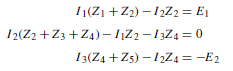
Mesh-current Analysis Mesh-current analysis is merely an extension of the use of Kirchhoff’s laws, explained in chapter 70. Figure 71.1 shows a network whose circulating cur- rents I1, I2 and I3 have been assigned to closed loops in the circuit rather than to branches. Currents I1 , I2 and I3 are called mesh-currents or loop-currents. […]
Continue reading…
Introduction to Network Analysis
Introduction Voltage sources in series-parallel networks cause currents to flow in each branch of the circuit and corresponding volt-drops occur across the circuit components. A.c. circuit (or network) analysis involves the determination of the currents in the branches and/or the voltages across components. The laws which determine the currents and voltage drops in a.c. networks […]
Continue reading…
D.c. Transients
Introduction When a d.c. voltage is applied to a capacitor C and resistor R connected in series, there is a short period of time immediately after the voltage is connected, during which the current flowing in the circuit and voltages across C and R are changing. Similarly, when a d.c. voltage is connected to a […]
Continue reading…
Single-phase Parallel a.c. Circuits
Introduction In parallel circuits, such as those shown in Figures 56.1 and 56.2, the voltage is common to each branch of the network and is thus taken as the reference phasor when drawing phasor diagrams. For any parallel a.c. circuit: These formulae are the same as for series a.c. circuits as used in chapter 55. […]
Continue reading…
Single-phase Series a.c. Circuits
Purely Resistive a.c. Circuit In a purely resistive a.c. circuit, the current IR and applied voltage VR are in phase. See Figure 55.1. Purely Inductive a.c. Circuit In a purely inductive a.c. circuit, the current IL lags the applied voltage VL by See Figure 55.2. In a purely inductive circuit the opposition to the flow […]
Continue reading…
D.c. Circuit Theory
Introduction The laws that determine the currents and voltage drops in d.c. networks are: (a) Ohm’s law (see chapter 40), (b) the laws for resistors in series and in parallel (see chapter 43), and (c) Kirchhoff’s laws. In addition, there are a number of circuit theorems that have been developed for solving problems in electrical […]
Continue reading…
Alternating Voltages and Currents
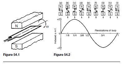
Introduction Electricity is produced by generators at power stations and then distributed by a vast network of transmission lines (called the National Grid system) to industry and for domestic use. It is easier and cheaper to generate alternating current (a.c.) than direct current (d.c.) and a.c. is more conveniently distributed than d.c. since its voltage […]
Continue reading…
Transistors
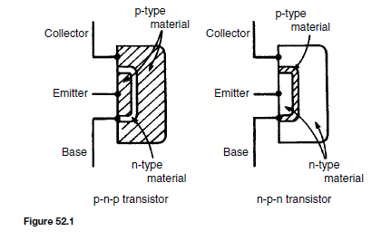
The Bipolar Junction Transistor The bipolar junction transistor consists of three regions of semiconductor material. One type is called a p-n-p transistor, in which two regions of p-type material sandwich a very thin layer of n-type material. A second type is called an n-p-n transistor, in which two regions of n-type material sandwich a very […]
Continue reading…
Electrical Measuring Instruments and Measurements
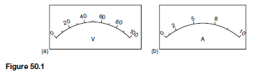
Introduction Tests and measurements are important in designing, evaluating, maintaining and servicing electrical circuits and equipment. In order to detect electrical quantities such as current, voltage, resistance or power, it is necessary to transform an electrical quantity or condition into a visible indication. This is done with the aid of instruments (or meters) that indicate […]
Continue reading…