The V-Curves of a Synchronous Motor
The magnitude of excitation current affects both the margin of stability and the reactive current of a synchronous motor. Let us analyse this relation by referring to the phasor/vector diagram of a phase of a synchronous motor connected to a large power system
(V = const), as shown in Fig 16. Given a constant retarding torque at the motor shaft, Tret = Tem its power P = Temɷrot will be likewise constant, so, as follows from Eq. (15.18) and Eq. (15.19), the products
E0 sin θ = ɷΨ0 sin θ = const
and
I cos φ = I act = const
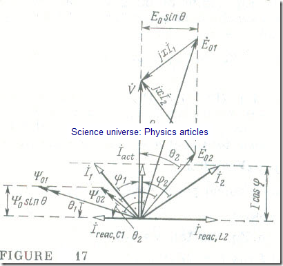
are always the same and independent of the excitation current. A combined phasor/vector diagram of a phase of a synchronous motor for Tret = const and for several values of the excitation (field) current If = VAr is shown in Fig 17. As If (excitation flux. linkage Ψ0) is reduced, the angle θ increases until the synchronous motor loses stability.
As follows from the phasor/vector diagram, the magnitude and effect of the stator current of a synchronous motor
İ = İact + İreac
depend on the excitation (field) current If When the field current is less than some limiting value, If < If.Iim (P), the stator current I has an inductive reactive component Ireac.L (φ > 0). When the field current exceeds some limiting value, If> If.Iim , the stator current has a capacitive reactive component Ireac. c (φ < 0). Hence, in the case of underexcitation the reactive power of a synchronous motor is inductive in its effect
QL = 3VIreac, L
In the case of overexcitation, it is capacitive in its effect
QC = 3VIreae. C
Accordingly, each phase of a synchronous motor connected to a large power system may be represented by an equivalent circuit consisting of a parallel combination of an equivalent resistive element whose resistance depends on the load torque, r = V/Iact = F (T1oad), and an equivalent inductive (capacitive) element whose inductance (capacitance) is a function of the load torque and the field current:
L = V/ɷIreac, L = F (If, Tload)
or
C = Ireac. C/ɷV = F (If, Tload)
If the load torque of the motor is zero, Tload = 0, then the equivalent circuit for a phase of a synchronous motor connected to a large power system will contain no resistive element, and the magnitude of the inductive (capacitive) element will be solely dependent on the field current.
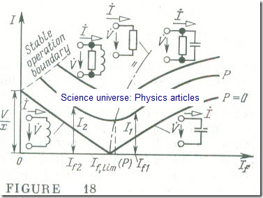
The plots relating the stator current or a synchronous motor connected to a large power system (V = const) to the field current for a constant load torque, Tload = const, are called the V–curves of the motor (Fig 18).
When no load torque is applied to the shaft of a synchronous motor (Tload = 0), then, on neglecting all forms of loss, it may be deemed that the stator current of a synchronous motor is purely reactive (see Fig 18, P = 0):
İ = İreac = (-Ė0+ V̇)/j = (V̇ + jɷΨ̇0 ) / j = F(If)


