Representing Algorithms-Flowcharts and Structure Diagrams
ALGORITHMS
An algorithm is a series of instructions or steps for the solution of a problem.
Examples of algorithms
1 A computer program.
2 A set of instructions in a kit telling you how to put the kit together.
3 A knitting pattern.
4 A cooking recipe.
5 A key of the type used in science to identify a specimen.
An algorithm is made up of three main types of component:
1 Sequence– a group of steps is carried out once each and in order.
2 Selection– a selection has two or more parts, but choice has to be made and only one of the parts is carried out.
3 Repetition (or iteration)-part of the algorithm is repeated, usually a fixed number of times or until some condition is met.
Example of a sequence
In the following recipe for Sweet and Sour Prawns steps 1 to 14 are to be carried out in order
and once each.
1 Place the prawns in a bowl with the sherry and seasonings.
2 Marinate for one hour.
3 Slice the onion.
4 Cut the pepper into wedges.
5 Put the oil in a saucepan.
6 Add the vegetables.
7 Fry gently until softened.
8 Add the pineapple.
9 Mix together the cornflour, soy sauce, vinegar and sugar and add.
10 Bring to the boil, stirring constantly.
11 Simmer for 3 minutes.
12 Add the prawns and sherry.
13 Bring to the boil.
14 Serve.
Example of selection
The following is a key for classifying vertebrate animals. Each of the numbered steps is a
selection with two parts. For a given animal only one of the parts will apply.
1 Does the animal have a backbone?
If YES it is a vertebrate-go to 2.
If NO it is an INVERTEBRATE.
2 Does it have internal gills AND fins?
If YES it is a FISH.
If NO go to 3.
3 Is part of its life history spent in water and part on land?
If YES it is an AMPHIBIAN.
If NO go to 4.
4 Does it have feathers?
If YES it is a BIRD?
If NO go to 5.
5 Does it have scales?
IF YES it is a REPTILE.
If NO go to 6.
6 It is a MAMMAL.
Example of repetition
The following is an extract from a knitting pattern. In the first row the sequence Purl 2, Knit
2 has to be repeated until the last 3 stitches in the row. There is another repetition, of Knit 2,
Purl 2, in the second row. Then these two rows have to be repeated until the knitted piece is 7 cm long.
1st row (RS facing) KI, * P2, K2, rep from * to last 3 sts, P2, KI
2nd row PI, * K2, P2, rep from * to last 3 sts, K2, PI.
Rep last 2 rows until rib measures 7 cm ending with a first row.
REPRESENTING ALGORITHMS USING DIAGRAMS
Structure diagrams
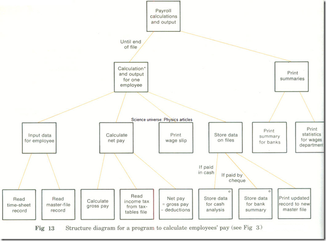
A structure diagram is a diagram which shows how an algorithm is broken down into more
and more detailed steps.
A structure diagram is ideal when an algorithm has been designed top down. It can then
show the refinement into more and more detailed steps.
Notation for structure diagrams
(Note: There are several methods of drawing structure diagrams. The one used in Fig.5 is based on the Jackson Method.)
1 All steps are shown in rectangles, each containing a brief statement of the step. (a) The detailed steps making up a step are shown below it and joined to it by lines. (b) A sequence is shown in order from left to right across the page.
2 Selection is shown by:
(a) Drawing a small circle in the top right of each of the choices and (b) Writing the condition for selecting that box just above it.
3 Repetition is shown by:
(a) Drawing an asterisk in the top right of the step being repeated and (b) Writing the condition for repeating just above it. (See Fig 6)
Example of a simple structure diagram
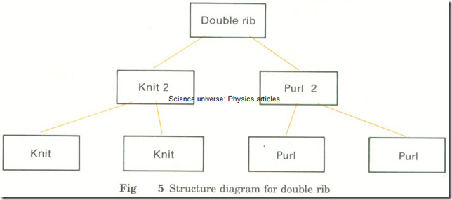
In the knitting pattern on page 81 the K2, P2 sequence is called a double rib. Double rib consists of Knit 2, Purl 2. Knit 2 consists of Knit, Knit.
Fig 5 Structure diagram for double rib
Example of a structure diagram showing repetition
In the knitting pattern on page 81 the 2nd row consists of Purl 1, a repeat of the double rib,
Fig 6 Structure diagram for first row of knitting pattern
Example of structure diagram showing selection
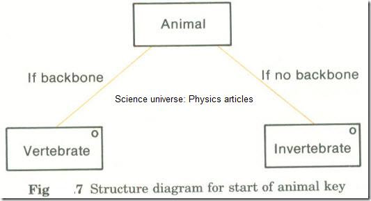
In the animal key on page 81 the selection between vertebrate and invertebrate would be represented as in Fig 7.
Fig 7 Structure diagram for start of animal key
Note: If a condition or a message is rather long, it can be replaced by a number and explained in the margin.
Flowcharts
In a flowchart of an algorithm:
1 The lines and arrows show the order in which steps are to be carried out.
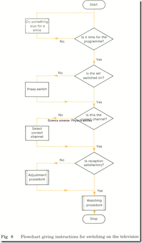
2 The messages in the symbols are the steps of the algorithm. (See Fig 8 )
Example of a flowchart of an algorithm
Fig 8 Flowchart giving instructions for switching on the television
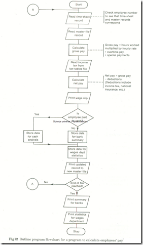
A program flowchart is a flowchart showing the sequence of operations performed by a computer program.
An outline program flowchart is a flowchart showing only the general operations carried out by a program. It should show:
1 all input and output operations,
2 the main modules of the program,
3 where execution of the program starts and stops.
A detailed program flowchart shows all operations carried out by a computer program. It should:
1 Show enough detail for someone to be able to write a program directly from it.
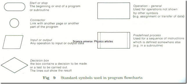
2 Avoid using messages aimed at a particular programming language. (See Fig 9 for the standard symbols used in program flowcharts.)
Fig 9 Standard symbols used in program flowchart
Examples of decision boxes
1 A decision-the box contains a question, and the flowlines out say ‘yes’ or ‘no’. (See Fig 10.)
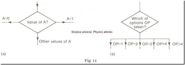
2 A test- the box contains the test and the flowlines out show the possible results. (See Fig 11.)
Notes on drawing program flowcharts
1 Use a template if possible- this has box shapes on it which you can draw round.
2 Draw all flowlines in either a vertical or a horizontal direction.
3 Use arrows where the direction is not clear. (If there are no arrows it is usually assumed that vertical lines are downwards and horizontal ones are left to right.)
4 Do not draw more than one line going in to a box.
5 Use ordinary English where possible.
6 Add notes in the right-hand margin if necessary.
7 Show only one entry point (e.g. a START symbol) and one exit point (e.g. a STOP symbol).
Example comparing a structure diagram and a program flowchart
The program represented in Figs 12 and 13 is used in the systems flowchart Fig 3 (labelled ‘Calculate pay, deduct tax, etc’). It calculates the pay of a group of employees.
Fig 12 Outline program flowchart for a program to calculate employees’ pay’
Fig 13 Structure diagram for a program to calculate employees’ pay

