counter
The term counter is used here to mean a digital-logic chip. A counter could be built from discrete transistors, but this approach is obsolete. Counters may also be devised from parts such as multiple relays, or a solenoid advancing a ratchet wheel, but such electro- mechanical devices are not included in this encyclopedia.
In this encyclopedia, a counter by definition has binary-weighted outputs with values 1, 2, 4, 8…. in decimal notation. The exception to this rule is a ring counter, which does not have binary-weighted outputs but is included here because its name identifies it as a counter. A shift register may be used as a ring counter, but is more versatile and has many other functions; hence it has a separate entry.
Gray code counters, in which successive outputs differ by only one binary digit, are not described in this encyclopedia.
What It Does
A counter can be used to count events, or can measure time in convenient intervals if it is connected with a component such as a quartz crystal that operates at a precise and reliable frequency. The counter receives input pulses (usually referred to as a clock input) and counts a pre- determined number of them before restarting from the beginning. It will repeat in this fashion so long as power is connected, and the clock pulses continue, and a reset signal is not supplied.
Almost all counters create some form of output during the count. Most commonly, the output is a pattern of high and low states expressing the number of clock pulses in binary code. Where a counter counts to a very high number before re- cycling, some intermediate binary digits may be omitted.
While standalone counter chips are not as widely used now as in the early days of computing, they still find application in industrial processes, small devices, and education, and can be used to control incremental devices such as stepper motors. They can be used in conjunction with microcontrollers.
Schematic Representation
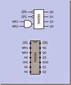
No specific logic symbol exists for a counter. It is most often shown in a schematic as a rectangle with clock input(s) and clear input(s) on the left and outputs on the right. An example appears in Figure 13-1, above a representation of the physical chip and its pinouts. The meaning of the abbreviations identifying the inputs, outputs, and control functions will be found in “How It Works” on page 132. Because the two MR inputs for this particular counter are ANDed inside the chip,
the AND symbol is included with the counter symbol.
Figure 13-1. Typical schematic representation of a counter, compared with the pinouts of the actual component.
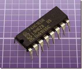
A counter chip is shown in Figure 13-2.
Figure 13-2. The 74HC163 shown in this photograph is a 4-bit synchronous counter capable of being preloaded with a starting value, and able to do a synchronous reset.
How It Works
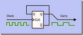
A counter is built from a chain of flip-flops, with each one triggering the next. JK, T-type, or D- type flip-flops may be used. For a thorough description of a flip-flop, see Chapter 11. In Figure 13-3, a D-type flip-flop is shown, triggered by each rising clock pulse.
Figure 13-3. When the complementary (NOT-Q) output from a D-type flip-flop is connected back to its input, the Q output frequency is half of the clock input frequency. See text for additional details.
Initially the Q output of the flip-flop is low, so its NOT-Q output (identified by Q with a bar above it) is high. This feeds back to the D input, but has no effect until the rising edge of the next clock pulse copies the high D input to the Q output. The Q output is now latched high while the NOT- Q output is latched low and feeds back to the D input. The triggering event has passed, so the low D input does not have any immediate effect. The rising edge of the next clock pulse copies the low state of the D input to the output, and changes the NOT-Q output to high, causing the cycle to repeat. As a result, the output frequency of the flip-flop is one-half of the input frequency from the clock. If the output is carried to the next flip-flop to become its clock input, once again the frequency will be divided by two.
Modulus and Modulo
The modulus of a counter is the number it will count up to, before it repeats. This is sometimes written incorrectly as modulo.
In fact, modulo is the name of an arithmetical operation, often abbreviated as MOD (usually capitalized, even though it is not an acronym). This operation consists of a division sum in which the remainder from the division is the result of the operation. Thus 100 modulo 5 gives a result of 0, because there is no remainder when 100 is divided by 5. But 100 modulo 7 gives a result of 2, because 2 is the remainder of the division operation.
To exacerbate the confusion, MOD is also used as an adjective referring to the modulus of a counter. Thus a MOD-4 counter has a modulus of 4, and a MOD-16 counter has a modulus of 16. As a general rule, when a counter is being described, modulo and MOD will mean the same thing as modulus. This may be confusing to people such as computer programmers who are already familiar with the correct usage of MOD as an arithmetical operator.
In a counter, to obtain a modulus that is not a power of two, logic gates inside the chip can intercept a particular value (such as 1010 binary, which is 10 decimal) and use this as a signal to restart the count at zero. External connections to the chip can achieve the same purpose.
Pin Identifiers
Abbreviations and acronyms are used in data- sheets to identify pin functions. These identifiers have not been standardized, and many variants exist.
CLK is the abbreviation most commonly used for the clock input, sometimes alternatively shown as CK or CP. If it is active-low, or if its falling edge will be active, a bar will be printed above it. Where a printed font does not permit an underscore to be placed in this way, CLK’ (the abbreviation followed by an apostrophe) may be used instead. Often two or more stages of a counter can be separately clocked, and the input pins will be identified with abbreviations such as CLK1 and CLK2, or 1CLK and 2CLK, or CKA and CKB, or CP1 and CP2, or similar.
Where a clock input is edge-triggered, this is indicated by a small triangle. The triangle can be seen in Figure 13-3.
CLR designates a pin which will clear the count and reset it back to zero. This signal is often active-low, indicated by a bar printed above the abbreviation.
In a schematic, a small circle, properly known as a bubble, may be placed at any input which is active-low. On a clock input, the circle indicates that it is falling-edge triggered. See Figure 11-16 for various implementations of symbols with flip- flop schematics.
The CLR operation may be synchronous (the pin state will not be recognized until the next clock pulse) or asynchronous (in which case the pin state overrides the clock and resets the counter immediately). MR stands for “Master Reset,” and has the same function as CLR.
Where two or more counters (or multiple stages within one counter) can be reset separately, more than one clear input will be shown, and may be identified with abbreviations such as CLR1 and CLR2, or MR1 and MR2.
Output pins will almost always be identified as Q0, Q1, Q2 … or QA, QB, QC … up to the maxi- mum necessary to express the modulus. If two or more counters are included in one chip, outputs may be prefixed with an appropriate number. Thus 2Q3 would be the third output in the second counter. Multiple counters in one chip are identified with numbers starting from 1.
Where internal flip-flops are shown, they will have identifiers such as FF1 or FF2. Each flip-flop will have its own clear function, identified as C or CD (the latter meaning “clear data”), and may have inputs labeled D1, D2, D3… in a D-type flip- flop or J and K in a JK flip-flop. See Chapter 11 for an explanation of flip-flop inputs and outputs.
The input to a counter is always imagined to be- gin from the left, and consequently the leftmost flip-flop shown in an internal schematic will ex- press the least significant bit of the current value of the count, even though a binary number is written with the least significant bit in the right- most place.
If a counter is capable of receiving parallel data as an input (explained below) it will have a pin labeled PE for parallel enable. It may also have a CE or CET pin, for count enable.
As is generally the case in logic chips, VCC or V+ are typically used to identify the positive power supply pin, while GND or V- will identify the negative-ground pin. NC means that a pin has no internal connection at all, and consequently re- quires no external connection.
Variants
change in a rapid but incremental sequence from the input to the output. This is also known as an asynchronous counter. Because the final state will not be valid until the clock pulse has rippled all the way through the counter (and through additional counters if they are cascaded together), a ripple counter will tend to suffer from a propagation delay of up to a microsecond. Ripple counters may also create output spikes or momentary transient count values that are invalid. Therefore, they are more suitable for applications such as driving a numeric display than for interfacing at high speed with other logic chips.
All counter chips use binary code internally, and the number of bits (binary digits) in the counter’s modulus will be the same as the number of internal flip-flops. A 4-bit counter (the usual mini- mum) will have a modulus of 24 which is 16. A 21- bit counter (the maximum typically available) will have a modulus of 221 which is 2,097,152. For higher moduli, counters can be chained together, each sending a carry signal to the next. This is known as a cascade.
Multiple counters, with different moduli, may be chained in a single chip. For example, in a digital clock that displays hours and minutes using the 60Hz frequency of an American domestic power supply as its timebase, the initial counting stage will have a modulus of 60, to count individual seconds. The next counting stages will have moduli of 60, 10, and 6, so that they can count from 00 to 59 minutes. Additional stages in the chip will tally hours.
A counter with a parallel input can be preloaded with an initial value (in binary code) from which it may count up or down. A parallel-enable pin may put the counter into a mode where the number can be jam loaded, meaning that it is jammed into the counter regardless of the clock state. Other types of counter are loaded synchronously.
Ripple versus Synchronous
In a ripple counter each internal flip-flop triggers the clock input of the next, so that their states In a synchronous counter, all the flip-flops are clocked simultaneously. A synchronous counter is better suited to operation at high speed.
Of the counter chips available today, about half are synchronous and half are asynchronous.
Ring, Binary, and BCD
A counter that activates output pins one at a time sequentially is said to have a decoded output. It is often referred to as a ring counter. It has the same number of output pins as its modulus. An example is the 4017B chip.
A binary counter is more common and has an encoded output, meaning that it will express the running total of the count in binary code through weighted outputs that typically have (decimal) values of 1, 2, 4, 8, and so on. A modulus-8 counter (often referred to as an octal counter) will require three outputs which represent the binary numbers 000, 001, 010, 011, 100, 101, 110, and 111
(decimal 0 through 7) before going back to 000 and repeating.
A modulus-16 counter, also known as a hexadecimal counter or a divide-by-16 counter, will have a binary output represented by four output pins, counting from 0000 through 1111 (decimal 0 through 15). Four-digit binary counters are very common, and their outputs are compatible with other components such as a decoder, which converts a binary-number input into a ring- counter-style output.
A decade counter is a modulus-10 binary counter. It is described as having a binary-coded decimal output (often expressed with the acronym BCD), using four weighted output pins which represent the numbers 0000, 0001, 0010, 0011, 0100, 0101, 0110, 0111, 1000, and 1001 (decimal 0 through
9) before repeating. Because this counter skips binary outputs from 1010 through 1111 (decimal 10 through 15), it is said to have a shortened modulus.
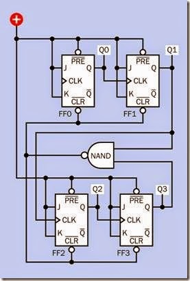
Figure 13-4 shows a schematic diagram of JK flip- flops in a decade ripple counter. The J and K in- puts are all tied to the positive power supply, as this causes the clock input to toggle the output high and low. Note that because the primary in- put is always shown at the left end of the component, the least significant output bit (Q0) is in the leftmost position.
To intercept binary 1010 (decimal 10), an internal NAND gate is used. Its output goes low when its two inputs, from Q1 and Q3, go high. The output from the NAND immediately activates the CLR function on all the flip-flops, so that as soon as the decade counter reaches 1010 (decimal 10), it resets itself to 0.
In this particular chip, the preload for each flip- flop is tied to the positive power supply, so that it is always inactive. In some counters, the pre- load feature of each flip-flop is accessible via pins outside the chip. This creates the potential hazard of preloading the counter with one of the numbers that it normally skips (for instance, 11 decimal in a decade counter). This is referred to as an invalid number or disallowed state. (This use of the term “state” refers only to the binary number stored in the counter’s flip-flops. It has noth- ing to do with the high-state or low-state voltages used to represent binary 0 or 1.)
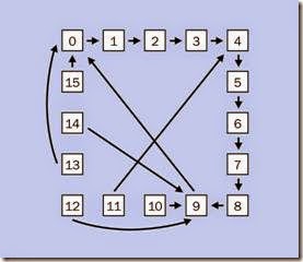
The counter’s datasheet should include a state diagram showing how the counter will deal with this situation. It may reset itself to a valid value after a maximum of two steps, but this can still cause confusion, depending on the application.
The state diagram for a 74HC192 counter is shown in Figure 13-5.
Figure 13-4. The internal logic of a synchronous decade counter that uses JK flip-flops.
Clock Sources
The clock input may be provided by a timer chip or by an RC network, which has the advantage of being able to run at a relatively low speed for purposes where this is desirable. It may alternatively be provided by a quartz crystal oscillating at a much higher frequency such as 1MHz. Successive counters may be necessary to reduce this value, depending on the application.
In some counters, the clock is built into the chip. More commonly, a resistor and capacitor may be used externally to establish a clock rate in con- junction with logic gates inside the chip. The datasheet for this type of component will include a formula for calculating the clock frequency from the resistor and capacitor values. The 4060B chip is an example.
Figure 13-5. A state diagram shows the transitions that a counter will make from each number to the next (in decimal notation), including the transitions which enable it to exit from disallowed states. This example is for a 74HC192 chip.
Rising Edge and Falling Edge
A counter may be designed to be triggered either by the rising edge or the falling edge of the clock input, or by its high or low logic state. Generally speaking, ripple counters use the falling edge, so that the final output from one counter can be- come the clock input of the next. In other words, when the most significant digit of the first counter changes from a high to low logic state, this transition toggles the least significant bit of the second counter.
Synchronous counters generally use the rising edge of the clock input. If multiple synchronous counters are cascaded, they must all share the same clock signal, and will all change their flip- flop states simultaneously.
Multiple Stages
It is common for a counter chip to contain two or more stages with differing moduli. To take a common example, a divide-by-2 stage and a divide-by-5 stage that are both present in a single chip can be used to create a decade counter by connecting external pins. The extra stages provide a choice of moduli if they are used individually.
Single and Dual
Counter chips may contain two counters of the same modulus. This is known as a dual counter. Dual 4-bit counter chips are common. Each counter can be used separately, or they can be cascaded, in which case the total modulus will be found by multiplying the individual moduli together.
High-State, Low-State, and Three-State Almost all counters use positive logic where a 1 is represented by a high state and 0 by a low state. Some counters allow an additional output state which has a high impedance and is equivalent to an open circuit. This feature is useful when two or more chips share the same output bus. It is discussed in the entry for shift registers in “Three-State Output” on page 126.
Descending Output
Most components only create an ascending count. The output can be converted to a de- scending count by passing each binary state through an inverter, but this will only work properly if the modulus is equal to the number of states. In a BCD counter, its inverted outputs will count from decimal 15 to decimal 6, not from decimal 9 to decimal 0.
A few counters are available which are designed to create a correct descending count. Other counters are available which allow the user to set the mode to ascending or descending. Examples are the 74×190 or 74×192 (where an acronym for the chip family will be substituted for the letter x).
A descending output is useful in combination with a parallel input, where a user may set an initial value from which the counter will descend to 0. With suitable logic, this can enable a user- specified delay period.
Programmable Counters
A programmable counter can usually allow a modulus ranging from 2 to more than 10,000. The counter counts down by dividing an initial number repeatedly with a value that is preset with binary inputs. An example is the 4059B chip.
Examples
Many counter specifications date back to the 4000 family of logic chips. Versions of them sub- sequently became available in the 74xx series, often with the old 4000 part number preceded by 74x (where x is replaced by a designation of the logic family). For example, a version of the 4518B dual BCD chip can be obtained as the 74HC4518. As is the case with all logic chips, this part number will be preceded by letter(s) desig- nating the particular manufacturer, with a suffix added to differentiate minor variants of the chip. The 74xx series has the advantage of higher speed and a greater ability to source or sink cur- rent at its output pins.
Most of the original CMOS chips, such as the 4518B, are still available, even in surface-mount versions. These offer the possible advantage of being able to use a higher power supply voltage.
Many counters offer multiple options such as different modulus values that can be selected by external pin connections. Some chips are tolerant of slow clock frequencies; others are not. Most are edge-triggered, but a few are level triggered. Some, such as the 4518B mentioned above, allow a choice of a rising-edge clock input and falling-edge clock input on different pins. For a specific application, it is really necessary to read a variety of datasheets to select the chip that is most suitable.
Values
As is the case with other logic chips, most counters in the through-hole 74xx series are intended
for 5VDC power supply while the older 4000 series may tolerate up to 18VDC. Surface-mount 74xx versions may use voltages as low as 2VDC.
See the section on logic gates in Chapter 10 for a discussion of acceptable high and low logic- input states. On the output side, the 4000 series chips are able to source or sink less than 1mA at 5VDC, but the 74HCxx series can usually manage around 20mA.
A few counters are capable of delivering more power through additional output stages that can drive LEDs. The 4026B decade counter is still being manufactured, capable of powering modest 7-segment displays. The 4033B has the addition- al option of blanking any leading zeros in a multi- digit display. Other chips that were designed for direct connection to LED numerals have become obsolete as the need for this application has di- minished. The 74C925, 74C926, 74C927, and 74C928 are examples. They may still be found from surplus outlets, but should not be specified in new circuit designs.
What Can Go Wrong
The entry that deals with problems affecting shift registers (see “What Can Go Wrong” on page 128), describes issues which also affect counters. The entry that deals with logic chips (see “What Can Go Wrong” on page 105), describes problems affecting all types of logic chips. In addition, the potential problems listed below are specific to counters.
Lock-Out
This is the condition which occurs if a counter with a shortened modulus is loaded with a binary state that is out of its range. Consult the data- sheet and study its state diagram to determine the most likely outcome if this problem occurs.
Asynchronous Artifacts
Because the flip-flops in an asynchronous (ripple) counter do not change simultaneously, they create very brief false outputs while the ripple
process is taking place. In a 4-bit counter, the bi- nary number 0111 (decimal 7) should be followed by 1000 (decimal 8). However, the right- most digit (i.e., the least significant bit) will change to a 0 initially, creating 0110 as a momentary binary output (decimal 6). The carry operation will then change the next digit to a 0, creating 0100 (decimal 4). The carry operation continues, changing the next digit to a 0, creating 0000. Finally the operation completes by creating 1000 as the correct output.
These intermediate states on the output pins are often referred to as glitches. Because they are extremely brief, they will be indetectable when a counter is used to drive a display. They can cause significant issues, however, if the outputs of the counter are connected with other logic chips.
Another type of asynchronous problem will occur if the clock speed is sufficiently high that a new pulse is received at the first flip-flop before the ripple of changing states has passed all the way through to the final flip-flop. This will result in a different brief invalid value on the output pins.
Noise
Old TTL-type counters, such as the 74LSxx series, are especially noise-sensitive. Adding a 0.1µF or 0.047µF bypass capacitor as close to the power supply pin as possible is recommended. Bread- boarding counters of this type may result in errors if a high-frequency clock is used, because conductors such as patch-cords are liable to pick up noise. Modern 74HCxx counters are preferable.

