vacuum-fluorescent display
The term vacuum-fluorescent display is seldom hyphenated, but the first two words are hyphenated here as they constitute an adjectival phrase. The acronym VFD is be- coming increasingly popular, although it is ambiguous, being also used to identify a variable frequency drive. In both instances, the acronym is printed without periods be- tween the letters.
The entry in this encyclopedia dealing with fluorescent lights does not include VFDs, because their purpose and design are very different. A VFD is an informational display, often showing numerals and letters, while a fluorescent light merely illuminates a room or work area. Although a VFD does use fluorescent phosphors, they are printed onto light-emitting segments of the display instead of being applied to the inside surfaces of a glass envelope.
A vacuum-fluorescent display or VFD superficially resembles a backlit monochrome LCD or an LED display, as it can represent alphanumeric characters by using segments or a dot matrix, and can also display simple shapes. It is often brighter than the other information display systems, and can emit an intense green phosphorescent glow that some people find aesthetically pleasing, even though a grid of very fine wires is superimposed internally over the displayed image.
There is no specific schematic symbol to represent a vacuum-fluorescent display.
How It Works
The display is mounted inside a sealed capsule containing a high vacuum. A widely spaced series of very fine wires, primarily made of tungsten, functions as a cathode, moderately heated to en- courage electron emission. The wires are often referred to as filaments.
A fluorescent light uses AC, and both of its electrodes are often confusingly referred to as cathodes. A VFD uses DC, and its cathode array has the function that one would expect, being connected with the negative side of the DC power supply.
Opposite the cathode, just a few millimeters away, is an anode that is subdivided into visible alphanumeric segments, symbols, or dots in a matrix. Each segment of the anode is coated with phosphors, and individual segments can be separately energized via a substrate. When electrons strike a positively charged anode segment, it emits visible light in a process of fluorescence. This behavior can be compared with that of a cathode-ray tube. However, the cathodes in a VFD are efficient electron emitters at a relatively low temperature, while the cathodes in a cathode- ray tube require substantial heaters.
Anode, Cathode, and Grid
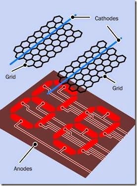
A grid consisting of a mesh of very fine wires is mounted in the thin gap between the filaments of the cathode and the segments of the anode. A simplified view of this arrangement is shown in Figure 25-1.
Figure 25-1. The basic elements of a vacuum-fluorescent display.
The polarity of the charge on the grid controls and diffuses electrons emitted by the cathode. If a grid section is negatively charged, it repels electrons and prevents them from reaching the
sections of the anode beneath it. If the grid section is positively charged, it encourages electrons to reach the anode. Thus, the grid functions in the same way as the grid in a triode vacuum tube, but its conductors are so thin, they are barely visible.
How to Use It
Electronic calculators used vacuum-fluorescent displays during the 1970s, before LED displays and LCDs became more competitive. Purely nu- meric VFD modules are still available as strings of digits, although they are becoming uncommon and have been replaced by alphanumeric dot- matrix modules where each VFD character is mounted in its own glass module on a separate substrate.
Figure 25-2 shows the interior of a Commodore calculator from the 1970s, with its nine-digit vacuum-fluorescent display enclosed in one glass capsule.
Figure 25-2. The vacuum-fluorescent display from a 1970s Commodore calculator.
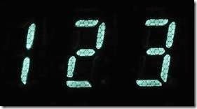
A closeup of three digits from the previous figure appears in Figure 25-3, showing the grid super- imposed above each numeral.
Figure 25-3. Three digits from the previous figure, showing the grid that controls their illumination.
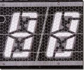
A tinted filter of the same color as the display is usually placed in front of it, to conceal some of its workings. Thus, the Commodore calculator used a green filter in front of its green numerals. Figure 25-4 shows two seven-segment numerals from another device, with the filter removed. This reveals not only the grid but also the horizontal wires that function as the cathode. Connections between the segments of the numerals and a backplane are also visible.
Figure 25-4. Seven-segment numerals viewed without a colored filter, revealing the cathode (horizontal wires) and the grid (wire mesh).
Modern Application
A modern VFD module is likely to be mated with a driver that converts 5VDC to the higher voltage (typically 50VDC to 60VDC) required for the dis- play. Built-in logic may offer the option to receive data via an 8-bit parallel bus or with SPI serial protocol, and will contain a character set. A typical display resolution is 128 x 64 pixels.
The combination of a grid and a segmented anode enables a VFD to be controlled by multiplexing. For instance, in a display of four seven- segment numerals, the same equivalent segments in all four numerals can be connected in parallel while a separate grid covers each numeral. When each grid is positively energized, it se- lects the corresponding numeral, and the on-off segment patterns appropriate to that numeral are supplied. This procedure is repeated for each numeral in turn. Persistence of vision makes it appear that they are all active simultaneously.
Variants
Color
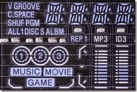
Although a VFD cannot provide a full-color display, selected anode segments can be coated with different phosphor colors, which can fluoresce simultaneously. Two or three individual colors are typically used, as in the display for a CD player where color helps to distinguish a variety of different functions. A closeup of a portion of the display from a CD player (with color filter re- moved) appears in Figure 25-5.
Figure 25-5. The lefthand section of a vacuum- fluorescent display from a CD player.
Character Sets and Pictorial Design
In the past, VFDs have combined seven-segment numerals in the same display as custom-shaped anodes. Solid-state gain meters in an audio amplifier, for instance, have used numerals beside a pictorial representation of gain levels resembling analog meters. The look and layout of a display of this type has been unique to a particular product.
Modern VFDs tend to use a generic dot-matrix display in which a character set in firmware dic-tates how patterns of dots are grouped to form numbers, letters, symbols, or icons.
The appearance of character sets generated with generic segments and dot-matrix arrays is thoroughly discussed and illustrated in the entry de- scribing liquid-crystal displays in Chapter 17. VFD alphanumeric modules are identical in vis- ual design to LCD modules, even though the internal electronics are different.
Comparisons
Two advantages of a VFD are that it functions well at low temperatures (unlike an LCD) and has sufficient brightness and contrast to be usable in sunlight (unlike many LED displays). It can be viewed from almost any angle.
Typical applications have included digital instrumentation in automobiles, information displays in audio and video consumer-electronics equipment, and numerical readouts in vending ma- chines, medical devices, and some digital clocks.
Because a VFD requires a relatively high voltage, has significant power consumption, can show only a limited range of fixed colors, and is more expensive than LED displays or LCDs, its popularity has declined since the end of the 1990s.
What Can Go Wrong
Fading
VFDs gradually fade with age, as a result of reduced electron emission from the electrodes or diminishing performance of the phosphor coatings. Increasing the working voltage can prolong the life of a display.


