Also known as a variable resistor; may be substituted for a rheostat.
When a voltage is applied across a potentiometer, it can deliver a variable fraction of that volt age. It is often used to adjust sensitivity, balance, input, or output, especially in audio equipment and sensors such as motion detectors.
A potentiometer can also be used to insert a variable resistance in a circuit, in which case it should really be referred to as a variable resistor, al though most people will still call it a potentiometer.
It can be used to adjust the power supplied to a circuit, in which case it is properly known as a rheostat, although this term is becoming obsolete. Massive rheostats were once used for pur poses such as dimming theatrical lighting, but solid-state components have taken their place in most high-wattage applications.
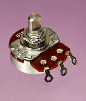
A full-size, classic-style potentiometer is shown in Figure 11-1.
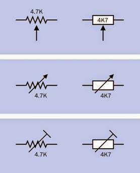
Schematic symbols for a potentiometer and other associated components are shown in Figure 11-2, with American versions on the left and European versions on the right in each case. The symbols for a potentiometer are at the top. The correct symbols for a variable resistor or rheostat are shown at center, although a potentiometer symbol may often be used instead. A
Figure 11-1. A generic or classic-style potentiometer, ap- proximately one inch in diameter.
preset variable resistor is shown at the bottom, often referred to as a trimmer or Trimpot. In these examples, each has an arbitrary rated resistance of 4,700Ω. Note the European substitution of K for a decimal point.
Figure 11-2. American (left) and European (right) symbols for a potentiometer, a rheostat, and a trimmer potentiometer, reading from top to bottom. The 4.7K value was chosen arbitrarily.
How It Works
A potentiometer has three terminals. The outer pair connect with the opposite ends of an inter nal resistive element, such as a strip of conductive plastic, sometimes known as the track. The third center terminal connects internally with a contact known as the wiper (or rarely, the pick- off), which touches the strip and can be moved from one end of it to the other by turning a shaft or screw, or by moving a slider.
If an electrical potential is applied between opposite ends of the resistive element, the voltage “picked off” by the wiper will vary as it moves. In this mode, the potentiometer works as a resistive voltage divider. For example, in a potentiometer with a linear taper (see “Variants,” coming up), if you attach the negative side of a 12V battery to the right-hand end terminal and the positive side to the left-hand end terminal, you will find an 8V
potential at the center terminal when the potentiometer has rotated clockwise through one- third of its range. In Figure 11-3, the base of the shaft (shown in black) is attached to an arm (shown in green) that moves a wiper (orange) along a resistive element (brown). The voltages shown assume that the resistive element has a linear taper and will vary slightly depending on wire resistance and other factors.
Because a potentiometer imposes a voltage reduction, it also reduces current flowing through it, and therefore creates waste heat which must be dissipated. In an application such as an audio circuit, small currents and low voltages generate negligible heat. If a potentiometer is used for heavier applications, it must be appropriately rated to handle the wattage and must be vented to allow heat to disperse.
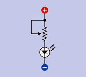
To use a potentiometer as a variable resistor or rheostat, one of its end terminals may be tied to the center terminal. If the unused end terminal is left unconnected, this raises the risk of picking up stray voltages or “noise” in sensitive circuits. In Figure 11-4, a potentiometer is shown adjusting a series resistance for an LED for demonstration purposes. More typically, a trimmer would be used in this kind of application, since a user is unlikely to need to reset it.
Variants
Linear and Log Taper
If the resistive element in a potentiometer is of constant width and thickness, the electrical potential at the wiper will change in ratio with the rotation of the wiper and shaft (or with movement of a slider). This type of potentiometer is said to have a linear taper even though its element does not actually taper.
For audio applications, because human hearing responds nonlinearly to sound pressure, a potentiometer that has a linear taper may seem to have a very slow action at one end of its scale and an abrupt effect at the other. This problem used to be solved with a non-uniform or tapered re
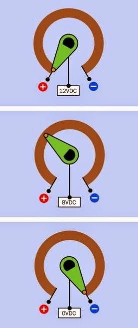 Figure 11-3. Inside a potentiometer. See text for details .
sistive element. More recently, a combination of resistive elements has been used as a cheaper option. Such a potentiometer is said to have an audio taper or a log taper (since the resistance
Figure 11-4. A potentiometer can be used to adjust a series resistance, as shown in this schematic. Tying the wiper to one of the end terminals reduces the risk of picking up electrical noise.
may vary as a logarithm of the angle of rotation). A reverse audio taper or antilog taper varies in the opposite direction, but this type has become very uncommon.
Classic-style Potentiometer
This consists of a sealed circular can, usually be tween 0.5” and 1” in diameter, containing a resistive strip that is shaped as a segment of a circle. A typical example is shown in Figure 11-1, al though miniaturized versions have become more common. A shaft mounted on the can turns the internal wiper that presses against the strip. For panel-mount applications, a threaded bush ing at the base of the shaft is inserted through a hole in the front panel of the electronics enclosure, and a nut is tightened on the bushing to hold the potentiometer in place. Often there is also a small offset index pin that, when paired with a corresponding front panel hole, will keep the pot from spinning freely.
Many modern potentiometers are miniaturized, and may be packaged in a box-shaped plastic
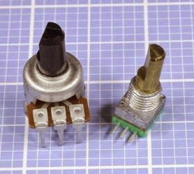
enclosure rather than a circular can. Their power ratings are likely to be lower, but their principle of operation is unchanged. Two variants are shown in Figure 11-5.
Figure 11-5. Two modern miniaturized potentiometers. At left: 5K. At right: 10K. Both are rated to dissipate up to 50mW.
The three terminals on the outside of a potentiometer may be solder lugs, screw terminals, or pins for direct mounting on a circuit board. The pins may be straight or angled at 90 degrees.
The resistive element may use carbon film, plastic, cermet (a ceramic-metal mixture), or resistive wire wound around an insulator. Carbon-film po tentiometers are generally the cheapest, where as wire-wound potentiometers are generally the most expensive.
Wire-wound potentiometers may handle more power than the other variants, but as the wiper makes a transition from one turn of the internal wire element to the next, the output will tend to change in discrete steps instead of varying more smoothly.
In a potentiometer with detents, typically a spring-loaded lever in contact with notched internal wheel causes the shaft to turn in discrete steps that create a stepped output even if the resistive element is continuous.
The shaft may be made of metal or plastic, with its length and width varying from one component to another. A control knob can be fitted to the end of the shaft. Some control knobs are push-on, others have a set screw to secure them. Shafts may be splined and split, or round and smooth, or round with a flat surface that matches the shape of a socket in a control knob and reuces the risk of a knob becoming loose and turning freely. Some shafts have a slotted tip to enable screwdriver adjustment.
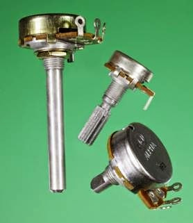
Some shaft options for full-size potentiometers are shown in Figure 11-6.
Figure 11-6. Three shaft options for potentiometers.
Multiple-Turn Potentiometer
To achieve greater precision, a track inside a potentiometer may be manufactured in the form of a helix, allowing the wiper to make multiple turns on its journey from one end of the track to the other. Such multiple-turn potentiometers typically allow 3, 5, or 10 turns to move the wiper from end to end. Other multiple-turn potentiometers may use a screw thread that advances a wiper along a linear or circular track. The latter is com
parable with a trimmer where multiple turns of a screwdriver are used to rotate a worm gear that rotates a wiper between opposite ends of a circular track.
Ganged Potentiometer
Two (or rarely, more) potentiometers can be stacked or combined so that their resistive elements and wipers share the same shaft but can use different voltages or have different taper. Each resistance-wiper assembly is known as a cup, and the potentiometers are said to be ganged.
Flat ganged potentiometers combine two resistive elements in one enclosure. Some dual ganged potentiometers are concentric, meaning that the pots are controlled separately by two shafts, one inside the other. Suitable concentric knobs must be used. You are unlikely to find these potentiometers sold as components in limited quantities.
Switched Potentiometer
In this variant, when the shaft is turned clockwise from an initial position that is fully counter- clockwise, it flips an internal switch connected to external terminals. This can be used to power-up associated components (for example, an audio amplifier). Alternatively, a switch inside a potentiometer may be configured so that it is activated by pulling or pushing the shaft.
Slider Potentiometer
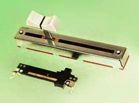
Also known as a slide potentiometer. This uses a straight resistive strip and a wiper that is moved to and fro linearly by a tab or lug fitted with a plastic knob or finger-grip. Sliders are still found on some audio equipment. The principle of operation, and the number of terminals, are identical to the classic-style potentiometer. Sliders typically have solder tabs or PC pins. In Figure 11-7, the large one is about 3.5” long, designed for mounting behind a panel that has a slot to allow the sliding lug to poke through. Threaded holes at either end will accept screws to fix the slider behind the panel. A removable plastic finger-grip
(sold separately, in a variety of styles) has been pushed into place. Solder tabs underneath the slider are hidden in this photo. The smaller slider is designed for through-hole mounting on a circuit board.
Figure 11-7. Slider potentiometers.
Trimmer Potentiometer
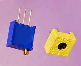
Often referred to as Trimpots, this is actually a proprietary brand name of Bourns. They are usu ally mounted directly on circuit boards to allow fine adjustment or trimming during manufacturing and testing to compensate for variations in other components. Trimmers may be single- turn or multi-turn, the latter containing a worm gear that engages with another gear to which the wiper is attached. Trimmers always have lin ear taper. They may be designed for screwdriver adjustment or may have a small knurled shaft, a thumb wheel, or a knob. They are not usually accessible by the end user of the equipment, and their setting may be sealed or fixed when the equipment is assembled. In Figure 11-8, the beige Spectrol trimmer is a single-turn design, whereas the blue trimmer is multi-turn. A worm gear inside the package, beneath the screw head, engages with an interior gear wheel that rotates the wiper.
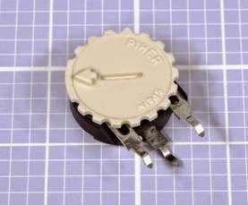
In Figure 11-9, a 2K trimmer potentiometer has a knurled dial attached to allow easy finger adjustment, although the dial also contains a slot for a flat-blade screwdriver.
Figure 11-8. Like most trimmers, these are designed for through-hole mounting on a circuit board.
Figure 11-9. A trimmer potentiometer with a knurled dial to facilitate finger adjustment.
How to Use it
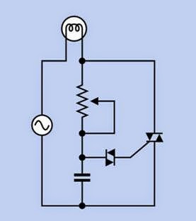
Potentiometers are widely used in lamp dimmers and on cooking stoves (see Figure 11-10). In these applications, a solid-state switching device such as a triac (described in Volume 2) does the actual work of moderating the power to the lamp or the stove by interrupting it very rapidly. The potentiometer adjusts the duty cycle of the power interruptions. This system wastes far less pow er than if the potentiometer controlled the lighting or heating element directly as a rheostat. Since less power is involved, the potentiometer can be small and cheap, and will not generate significant heat.
Figure 11-10. Typical usage of a potentiometer in conjunction with a diac, triac, and capacitor to control the bright-
ness of an incandescent bulb, using an AC power supply.
Diacs and triacs are discussed in Volume 2.
The classic-style potentiometer was once used
universally to control volume, bass, and treble on audio equipment but has been replaced increasingly by digital input devices such as tactile switches (see “Tactile Switch” (page 34)) or ro tational encoders (see Chapter 8), which are more reliable and may be cheaper, especially when assembly costs are considered.
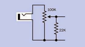
Because true logarithmic potentiometers have become decreasingly common, a linear potentiometer in conjunction with a fixed resistor can be used as a substitute, to control audio input. See Figure 11-11.
Figure 11-11. In this circuit, a 100K linear potentiometer is used in conjunction with a 22K resistor to create an approximately logarithmic volume control for an audio sys- tem with input coming from a mono jack socket at left.
A potentiometer may be used to match a sensor or analog input device to an analog-digital converter, or it can calibrate a device such as a temperature or motion sensor.
What Can Go Wrong
Wear and Tear
Since classic-style potentiometers are electro mechanical devices, their performance will deteriorate as one part rubs against another. The long open slot of a slider potentiometer makes it especially vulnerable to contamination with dirt, water, or grease. Contact-cleaner solvent, lubricant-carrying sprays, or pressurized “duster” gas may be squirted into a potentiometer to try to extend its life. Carbon-film potentiometers are the least durable and in audio applications will eventually create a “scratchy” sound when they are turned, as the resistive element deteriorates.
If the wiper deteriorates to the point where it no longer makes electrical contact with the track, and if the potentiometer is being used as a vari able resistor, two failure modes are possible, shown in Figure 11-12. Clearly the right-hand schematic is a better outcome. This is an argument for always tying the wiper to the “unused” end of the track.
If you are designing a circuit board that will go through a production process, temperature variations during wave soldering, and subsequent
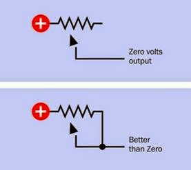 Figure 11-12. If the wiper of a potentiometer breaks (indicated by the loose arrow head) as a result of wear and tear, and the potentiometer is being used as a variable resistor, the voltage from it will drop to zero (top schematic) unless the wiper has been tied to one end of the track
(bottom schematic).
washing to remove flux residues, create hostile conditions for potentiometers, especially sliders where the internal parts are easily contaminated. It will be safer to hand-mount potentiometers after the automated process.
Knobs that Don’t Fit
Control knobs are almost always sold separately from potentiometers. Make sure the shaft of the potentiometer (which may be round, round- with-flat, or knurled) matches the knob of your choice. Note that some shaft diameters are ex pressed in inches, while others are metric.
Nuts that Get Lost
For panel-mounted potentiometers, a nut that fits the thread on the bushing is almost always included with the potentiometer; an additional nut and lock washer may also be supplied. Be cause there is no standardization of threads on potentiometers, if you lose a nut, you may have some difficulty finding an exact replacement.
A Shaft that Isn’t Long Enough
When choosing a shaft length, if in doubt, buy a potentiometer with a long shaft that you can cut to the desired length.
Sliders with No Finger Grip
Slider potentiometers are often sold without a knob or plastic finger-grip, which must be ordered separately and may be available in different styles. The finger-grip usually push-fits onto the metal or plastic tab or lug that moves the slider to and fro.
Too Big to Fit
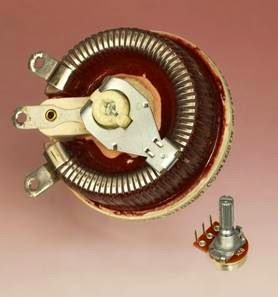
Check the manufacturer’s datasheet if you need to know the physical size of the potentiometer. Photographs may be misleading, as a traditional- style potentiometer that is 0.5” in diameter looks much the same as one that is 1” in diameter. High- wattage potentiometers will be more costly and physically large (2 to 3 inches in diameter). See Figure 11-13.
Overheating
Be sure to leave sufficient air space around a high-wattage potentiometer. Carefully calculate the maximum voltage drop and current that you may be using, and choose a component that is appropriately rated. Note that if you use the potentiometer as a rheostat, it will have to handle more current when its wiper moves to reduce its resistance. For example, if 12VDC are applied through a 10-ohm rheostat to a component that has a resistance of 20 ohms, current in the circuit will vary from 0.4 amps to 0.6 amps depending on the position of the rheostat. At its maximum setting, the rheostat will impose a 4V voltage drop and will therefore dissipate 1.6 watts from the full length of its resistive element. If the rheostat is reset to impose only a 4-ohm resistance, the voltage drop that it imposes will be 2V, the current in the circuit will be 0.5 amps, and the rheostat will therefore dissipate 1 watt from 4/10ths of the length of its resistive element. A
wire-wound potentiometer will be better able to handle high dissipation from a short segment of its element than other types of rheostat. Add a fixed resistor in series with a rheostat if necessary to impose a limit on the current.
Figure 11-13. The large potentiometer is approximately 3” in diameter, rated at 5 ohms, and able to handle more than 4 amps. The small potentiometer is 5/8” diameter, rated at 2K and 1/4 watt, with pins designed for through- hole insertion in a circuit board, and a grooved shaft that accepts a push-on knob. Despite the disparity in size, the principle of operation and the basic features are identical.
When using a trimmer potentiometer, limit the current through the wiper to 100mA as an absolute maximum value.
The Wrong Taper
When buying a potentiometer, remember to check the specification to find out whether it has linear or audio/log taper. If necessary, attach a meter, with the potentiometer set to its center position, to verify which kind of taper you have. While holding the meter probes in place, rotate the potentiometer shaft to determine which way an audio/log taper is oriented.

