Capacitance
In This Chapter:
✔ Capacitance
✔ Parallel-Plate Capacitor
✔ Capacitors in Combination
✔ Energy of a Charged Capacitor
✔ Charging a Capacitor
✔ Discharging a Capacitor
Capacitance
A capacitor is a system that stores energy in the form of an electric field. In its simplest form, a capacitor consists of a pair of parallel metal plates separated by air or other insulating material.
The potential difference V between the plates of
a capacitor is directly proportional to the charge Q on either of them, so the ratio Q/V is always the same for a particular capacitor. This ratio is called the capacitance C of the capacitor:
The unit of capacitance is the farad (F), where 1 farad = 1 coulomb/ volt. Since the farad is too large for practical purposes, the microfarad and picofarad are commonly used, where A charge of 10−6 C on each plate of 1-mF capacitor will produce a potential difference of V = Q/C = 1 V between the plates.
Parallel-Plate Capacitor
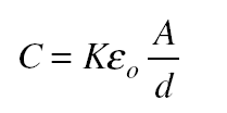
A capacitor that consists of parallel plates each of area A separated by the distance d has a capacitance of The constant ε0 is the permittivity of free space; its value is
 The quantity K is the dielectric constant of the material between the capacitor plates; the greater K is, the more effective the material is in diminishing an electric field.
Note!
For free space, K = 1; for air, K = 1.0006; a typical value for glass is K = 6; and for water, K = 80.
Capacitors in Combination
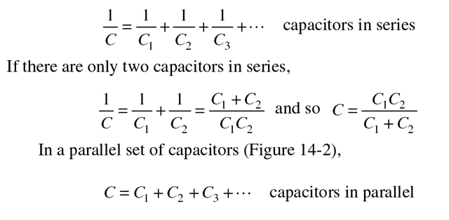
The equivalent capacitance of a set of connected capacitors is the capacitance of the single capacitor that can replace the set without changing the
Figure 14-1
properties of any circuit it is part of. The equivalent capacitance of a set of capacitors joined in series (Figure 14-1) is
Solved Problem 14.1 Find the equivalent capacitance of three capaci- tors whose capacitances are 1, 2, and 3 mF that are connected in: (a) se- ries and (b) parallel.
Solution.
(a) n series, the equivalent capacitance can be found by:
![Capacitance ]_Page_096_Image_0002 Capacitance ]_Page_096_Image_0002](http://lh6.ggpht.com/-EN8edlFX9KI/VE5zGZma6JI/AAAAAAAArs8/i0X4cNFri88/Capacitance%252520%25255D_Page_096_Image_0002_thumb.jpg?imgmax=800)
(b) n parallel, the equivalent capacitance can be found by:
Energy of a Charged Capacitor
To produce the electric field in a charged capacitor, work must be done to separate the positive and negative charges. This work is stored as electric potential energy in the capacitor. The potential energy W of a capacitor of capacitance C whose charge is Q and whose potential difference is V given by
Charging a Capacitor
When a capacitor is being charged in a circuit such as that of Figure 14-3, at any moment the voltage Q/C across it is in the opposite direction to the battery voltage V and thus tends to oppose the flow of additional charge. For this reason, a capacitor does not acquire its final charge the instant it is connected to a battery or other source of emf. The net potential difference when the charge on the capacitor is Q is V − (Q/C), and the current is then
As Q increases, its rate of increase I = ∆Q/∆t decreases. Figure 14-4 shows how Q, measured in percent of final charge, varies with time when a capacitor is being charged; the switch of Figure 14-3 is closed at t = 0.
The product RC of the resistance R in the circuit and the capacitance C governs the rate at which the capacitor reaches its ultimate charge of Q0 = CV. The product RC is called the time constant T of the circuit. Af-
ter a time equal to T, the charge on the capacitor is 63 percent of its final value.
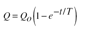
The formula that governs the growth of charge in the circuit of Fig- ure 14-3 is
where Qo is the final charge CV and T is the time constant RC. Figure 14-4 is a graph of that formula. It is easy to see why Q reaches 63 percent of Qo in time T. When t = T, t/T = 1 and
Discharging a Capacitor
When a charged capacitor is discharged through a resistance, as in Fig- ure 14-5, the decrease in charge is governed by the formula
where again T = RC is the time constant. The charge will fall to 37 per- cent of its original value after time T (Figure 14-6). The smaller the time constant T, the more rapidly a capacitor can be charged or discharged.
Figure 14-4
Solved Problem 14.2 A 20-mF capacitor is connected to a 45-V battery through a circuit whose resistance is 2000 W. (a) What is the final charge on the capacitor? (b) How long does it take for the charge to reach 63 per- cent of its final value?
Figure 14-5
Figure 14-6


![Capacitance ]_Page_096_Image_0001 Capacitance ]_Page_096_Image_0001](http://lh3.ggpht.com/-HIDqh31BzZ4/VE5y8r2CqlI/AAAAAAAArsM/IZsHhxaSxb4/Capacitance%252520%25255D_Page_096_Image_0001_thumb.jpg?imgmax=800)

![Capacitance ]_Page_098_Image_0001 Capacitance ]_Page_098_Image_0001](http://lh6.ggpht.com/-v042HIihqe4/VE5zVoM90lI/AAAAAAAAruM/KTlNH7XGnuU/Capacitance%252520%25255D_Page_098_Image_0001_thumb%25255B1%25255D.jpg?imgmax=800)

![Capacitance ]_Page_099_Image_0002 Capacitance ]_Page_099_Image_0002](http://lh3.ggpht.com/-TtK7RpsS9u8/VE5zhDn8ugI/AAAAAAAArvM/VHbkLdxxojI/Capacitance%252520%25255D_Page_099_Image_0002_thumb%25255B1%25255D.jpg?imgmax=800)

![Capacitance ]_Page_099_Image_0001 Capacitance ]_Page_099_Image_0001](http://lh3.ggpht.com/-5XgfIveNdwo/VE5zngz-Q4I/AAAAAAAArvs/V0Awz_IjkSI/Capacitance%252520%25255D_Page_099_Image_0001_thumb%25255B1%25255D.jpg?imgmax=800)
![Capacitance ]_Page_100_Image_0001 Capacitance ]_Page_100_Image_0001](http://lh3.ggpht.com/-FBG-iopBvYg/VE5zr2F1iGI/AAAAAAAArv8/oLPP0TmONCQ/Capacitance%252520%25255D_Page_100_Image_0001_thumb%25255B1%25255D.jpg?imgmax=800)