8.1 Potential Flow
BASICS
When a body is moving in an otherwise stationary fluid, there is no vorticity present in the undisturbed fluid. To create a steady flow, a uniform flow with the body’s velocity is superimposed on the flow field so that the vorticitfree flow moves by the stationary body, as in a wind tunnel. For high Reynolds-number flows, the viscous effects are concentrated in the boundary layer and the wake (the wake includes the separated region). For a streamlined body and over the front part of a blunt body, the flow outside the boundary layer is free of viscous effects so it is an inviscid flow. The solution of the inviscid flow problem provides the velocity field and the pressure field. The pressure is not significantly influenced by the boundary layer so the pressure integrated over the body’s surface will provide the lift. The velocity at the surface of the body2 from the inviscid flow solution will be the velocity at the outer edge of the thin boundary layer needed in the boundary-layer solution (to be presented in Sec. 8.5). So, before the boundary layer can be analyzed on a body, the inviscid flow must be known.
A potential flow (or irrotational flow), is one in which the velocity field can be expressed as the gradient of a scalar function, that is,
where f is the velocity potential. For a potential flow, the vorticity is zero:
This can be shown to be true by expanding in rectangular coordinates and using Eq. (8.7).
To understand why vorticity cannot exist in regions of an irrotational flow, con- sider the effect of the three types of forces that can act on a cubic fluid element: the pressure and body forces act through the center of the element, and consequently, cannot impart a rotary motion to the element. It is only the viscous shear forces that are able to give rotary motion to fluid particles. Hence, if the viscous effects are nonexistent, vorticity cannot be introduced into an otherwise potential flow.
If the velocity is given by Eq. (8.7), the continuity equation (5.8) for an incompressible flow provides
![]() which is the famous Laplace equation. In rectangular coordinates it is written as
which is the famous Laplace equation. In rectangular coordinates it is written as
 With the required boundary conditions, this equation could be solved. But, rather than attempting to solve the resulting boundary-value problem directly, we will restrict our interest to plane flows, identify several simple flows that satisfy Laplace equation, and then superimpose those simple flows to form more complex flows of interest. Since Laplace equation is linear, the superimposed flows will also satisfy Laplace equation.
First, however, we will define another scalar function that will be quite useful in our study. For the plane flows of interest, the stream function y, is defined by
so that the continuity equation (5.8) with ∂w/∂ z = 0 (for a plane flow) is satisfied for all plane flows. The vorticity [see Eqs. (8.8) and (3.14)] then provides
 The stream function also satisfies the Laplace equation. So, from the above equations we have.
The equations between f and y in Eq. (8.14) form the Cauchy-Riemann equations and f and y are referred to as harmonic functions. The function f + iy is the complex velocity potential. The mathematical theory of complex variables is thus applicable to this subset of fluid flows: steady, incompressible, inviscid plane flows.
Three items of interest contained in the above equations are:
• The stream function is constant along a streamline.
• The streamlines and lines of constant potential intersect at right angles.
• The difference of the stream functions between two streamlines is the flow rate q per unit depth between the two streamlines, i.e., q = ψ 2 − ψ1.
EXAMPLE 8.5
Show that y is constant along a streamline.
Solution
A streamline is a line to which the velocity vector is tangent. This is expressed in vector form as V × dr = 0, which, for a plane flow (no z variation), using dr = dx i + dy j takes the form udy − vdx = 0. Using Eq. (8.11), this becomes
This is the definition of dy from calculus, thus dy = 0 along a streamline, or, in other words, y is constant along a streamline.
SEVERAL SIMPLE FLOWS
Several of the simple flows to be presented are much easier understood using polar (cylindrical) coordinates. The Laplace equation, the continuity equation, and the expressions for the velocity components for a plane flow (see Table 5.1) are
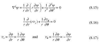 where the expressions relating the velocity components to the stream function are selected so that the continuity equation is always satisfied. We now define four simple flows that satisfy the Laplace equation:
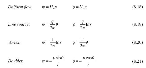 These simple plane flows are shown in Fig. 8.8. If a y-component is desired for the uniform flow, an appropriate term is added. The source strength q in the line source is the flow rate per unit depth; adding a minus sign creates a sink. The vortex strength
Γ is the circulation about the origin, defined as
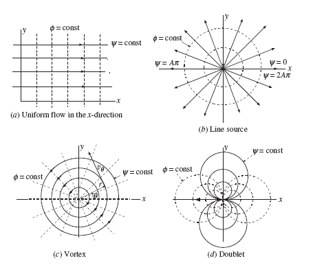 Figure 8.8 Four simple plane potential flows.
where L is a closed curve, usually a circle, about the origin with clockwise being positive. The heavy arrow in the negative x-direction represents the doublet strength m in Fig. 8.8d. (A doublet can be thought of as a source and a sink of equal strengths separated by a very small distance.)
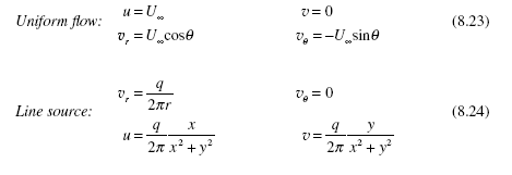
The velocity components are used quite often for the four simple flows presented. They follow for both polar and rectangular coordinates:
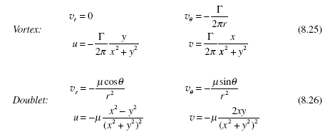 These four simple flows can be superimposed to create more complicated flows of interest. This will be done in the following section.
EXAMPLE 8.6
If the stream function of a flow is given as ψ = Aθ, determine the potential function φ .
Solution
We use Eq. (8.17) to relate the stream function to the potential function assuming polar coordinates because of the presence of θ :
Since we are only interested in the derivatives of the potential functions needed to provide the velocity and pressure fields, we simply let the constant be zero and thus
So, we see that the potential function can be found if the stream function is known. Conversely, the stream function can be found if the potential function is known.
SUPERIMPOSED FLOWS
The simple flows just defined can be superimposed to create complicated plane flows. Divide a surface, such as an airfoil, into a large number of segments and position sources or sinks (or doublets) at the center of each segment; in addition, add a uniform flow and a vortex. Then, adjust the various strengths so that the normal velocity component at each segment is zero and the rear stagnation point is located at the trailing edge. Obviously, a computer program would be used to create such a flow. We will not attempt it in this book but will demonstrate how flow around a circular cylinder can be created.
Superimpose the stream functions of a uniform flow and a doublet:
Thus, two stagnation points occur at q = 0° and 180°. The streamline pattern would appear as in the sketch of Fig. 8.9. The circular streamline represents the cylinder, which is typically a solid, and hence our interest is in the flow outside the circle. For a real flow, there would be a separated region on the rear of the cylinder but the flow over the front part (perhaps over the whole front half, depending on the Reynolds number) could be approximated by the potential flow shown in the figure. The velocity that exists outside the thin boundary layer that would be present on a real
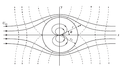 Figure 8.9 Potential flow around a circular cylinder. (The dashed lines are lines of constant f.)
cylinder would be approximated as the velocity on the cylinder of the potential flow, that is, it would be given by
 The pressure that would exist on the cylinder’s surface would be found by applying Bernoulli’s equation between the stagnation point (V = 0) where the pressure is p0 and some general point at rc and θ:
This pressure would approximate the actual pressure for high Reynolds-number flows up to separation. For low Reynolds-number flows, say below Re ≈ 50, viscous effects are not confined to a thin boundary layer so potential flow does not approximate the real flow.
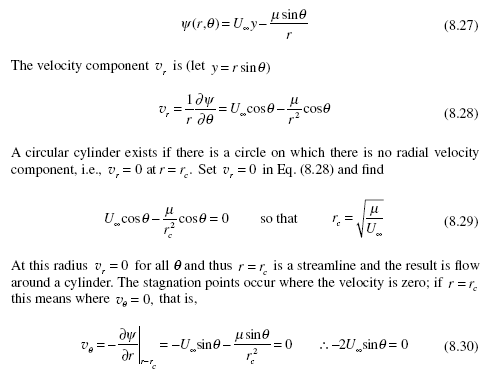
To create flow around a rotating cylinder, as in Fig. 8.10, add a vortex to the stream function of Eq. (8.27) [use the cylinder’s radius of Eq. (8.29)]:
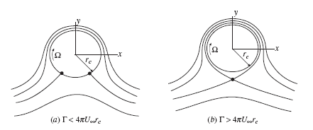 Figure 8.10 Flow around a rotating cylinder.
The cylinder’s radius remains unchanged since a vortex does not affect vr . The stagnation points change, however, and are located by letting vθ = 0 on r = rc:
![]() (8.35) is not valid (this would give sinθ > 1 ), so the stagnation point exists off the cylinder as shown in Fig. 8.10b. The radius is found by setting the velocity components equal to zero and the angle q = 270°. The pressure on the surface of the rotating cylinder is found using Bernoulli’s equation to be
(8.35) is not valid (this would give sinθ > 1 ), so the stagnation point exists off the cylinder as shown in Fig. 8.10b. The radius is found by setting the velocity components equal to zero and the angle q = 270°. The pressure on the surface of the rotating cylinder is found using Bernoulli’s equation to be
If p dA is integrated around the surface of the cylinder, the component in the flow direction, the drag, would be zero and the component normal to the flow direction, the lift, would be
 It turns out that this expression for the lift is applicable for all cylinders including the airfoil. It is known as the Kutta-Joukowski theorem; it is exact for potential flows and is an approximation for real flows.
EXAMPLE 8.7
A 20-cm-diameter cylinder rotates clockwise at 200 rpm in an atmospheric air stream flowing at 10 m/s. Locate any stagnation points and find the minimum pressure.
Solution
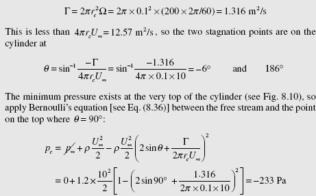
First, find the circulation. It is Γ= 0∫L V ⋅ ds which is the velocity rc Ω multiplied by 2πrc , since V is in the direction of ds on the cylinder’s surface:
using P= 1.2 kg/m3 for atmospheric air. (If the temperature is not given, assume
standard conditions.)
8.2 Boundary-Layer Flow
GENERAL INFORMATION
The observation that for a high Reynolds-number flow all the viscous effects can be confined to a thin layer of fluid near the surface gives rise to boundary-layer theory. Outside the boundary layer the fluid acts as an inviscid fluid. So, the potential flow theory of the previous section provides both the velocity at the
outer edge of the boundary layer and the pressure at the surface. In this section we will provide the integral and differential equations needed to solve for the velocity distribution in the boundary layer. But, those equations are quite difficult to solve for curved surfaces, so we will restrict our study to flow on a flat plate with zero pressure gradient.
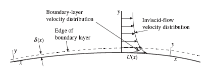
The outer edge of a boundary layer cannot be observed, so we arbitrarily assign its thickness d (x), as shown in Fig. 8.11, to be the locus of points where the velocity is 99 percent of the free-stream velocity U(x) (the velocity at the surface from the inviscid flow solution). The pressure at the surface is not influenced by the presence of the thin boundary layer, so it is the pressure on the surface from the inviscid flow. Note that the xy-coordinate system is oriented so that the x-coordinate is along the surface; this is done for the boundary-layer equations and is possible because the boundary layer is so thin that curvature terms do not appear in the describing equations.
A boundary layer is laminar near the leading edge or near a stagnation point. It undergoes transition at xT to a turbulent flow if there is sufficient length, as shown in Fig. 8.12. This transition occurs when the critical Reynolds number U x /v = 5 × 10³
on smooth, rigid flat plates in a zero pressure-gradient flow with low free-stream
Figure 8.13 Laminar and turbulent boundary-layer profiles.
fluctuation intensity3 and U x /n = 3 × 10⁵ for flow on rough flat plates or with high free-stream fluctuation intensity (intensity of at least 0.1). The transition region from laminar to turbulent flow is relatively short and is typically ignored so a turbulent flow is assumed to exist at the location of the first burst.
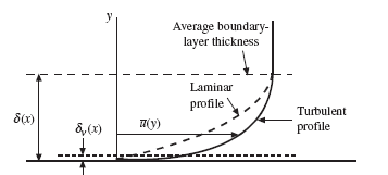
The turbulent boundary layer thickens more rapidly than a laminar boundary layer and contains significantly more momentum (if it has the same thickness), as observed from a sketch of the velocity profiles in Fig. 8.13. It also has a much greater slope at the wall resulting in a much larger wall shear stress. The instantaneous turbulent boundary layer varies randomly with time and position and can be 20 percent thicker or 60 percent thinner at any position at an instant in time or at any time at a given position. So, we usually sketch a time-average boundary-layer thickness. The viscous wall layer with thickness dv, in which turbulent bursts are
thought to originate, is quite thin compared to the boundary-layer thickness, as
shown.
It should be kept in mind that a turbulent boundary layer is very thin for most
|
applications. On a flat plate with U
= 5 m/s, the boundary layer would be about 7 cm
thick after 4 m. If this were drawn to scale, the fact that the boundary layer is very thin would be quite apparent. Because the boundary layer is so thin and the velocity varies from zero at the wall to U(x) at the edge of the boundary layer, it is possible to approximate the velocity profile in the boundary layer by assuming a parabolic or cubic profile for a laminar layer and a power-law profile for a turbulent layer. With the velocity profile assumed, the integral equations, which follow, give the quantities of interest.
THE INTEGRAL EQUATIONS
An infinitesimal control volume of thickness dx is shown in Fig. 8.14 with mass fluxes in (b) and momentum fluxes in (d). The continuity equation provides the mass flux m top that crosses into the control volume through the top; it is
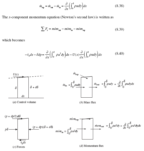 Figure 8.14 The infinitesimal control volume for a boundary layer.
where we have neglected4 pdd and dpdd since they are of smaller order than the remaining terms; we also used mo·mtop = U (x)m· top . Divide by (–dx) and obtain the von Karman integral equation:
Ordinary derivatives have been used since after the integration only a function of x remains (d is a function of x). Also, the density r is assumed constant over the boundary layer.
For flow on a flat plate with zero pressure gradient, i.e., U(x) = U∞ and ∂ p/∂ x = 0, Eq. (8.41) can be put in the simplified form
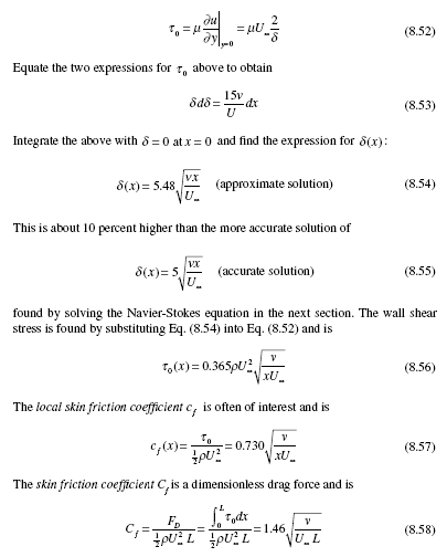
If a velocity profile u(x, y) is assumed for a particular flow, Eq. (8.42) along with![]() allows both d (x) and t0(x) to be determined. Two additional lengths are used in the study of boundary layers. They are the displacement thickness dd and the momentum thickness q defined by
allows both d (x) and t0(x) to be determined. Two additional lengths are used in the study of boundary layers. They are the displacement thickness dd and the momentum thickness q defined by
The displacement thickness is the distance the streamline outside the boundary layer is displaced because of the slower moving fluid inside the boundary layer. The momentum thickness is the thickness of a fluid layer with velocity U that possesses the momentum lost due to viscous effects; it is often used as the characteristic length for turbulent boundary-layer studies. Note that Eq. (8.42) can be written as
 LAMINAR AND TURBULENT BOUNDARY LAYERS
The boundary conditions that must be met for the velocity profile in a boundary layer on a flat plate with a zero pressure gradient are
For a laminar boundary layer, we can either solve the x-component Navier-Stokes equation or we can assume a profile such as a parabola. Since the boundary layer is so thin, an assumed profile gives rather good results. Assume the parabolic profile
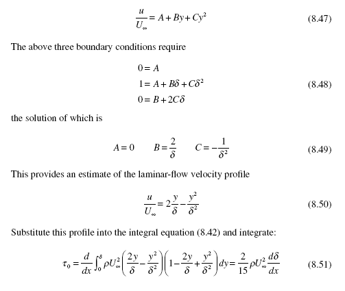 The wall shear stress is also given by
The more accurate coefficients for t0, cf , and Cf are 0.332, 0.664, and 1.33, so the assumption of a parabolic velocity profile for laminar boundary-layer flow has an error of about 10 percent.
Turbulent Boundary Layers
For a turbulent boundary layer we often assume a power-law velocity profile5 as we did for flow in a pipe. It is
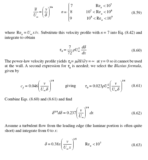 Substitute this into the Blasius formula and find the local skin friction coefficient to be
 The above formulas can actually be used up to Re ≅ 108 without substantial error.
If there is a significant laminar part of the boundary layer, it should be included. If transition occurs at Re = 5 × 10⁵, then the skin friction coefficient should be modified as
For a rough plate, recall that Re = 3 × 10⁵; the constant of 1700 in Eq. (8.66) should be replaced with 1060.
The displacement and momentum thicknesses can be evaluated using the power- law velocity profile to be
There are additional quantities often used in the study of turbulent boundary layers. We will introduce two such quantities here. One is the shear velocity uτ defined to be
 It is a fictitious velocity and often appears in turbulent boundary-layer relation- ships. The other is the thickness dv of the highly fluctuating viscous wall layer, displayed in Figs. 8.12 and 8.13. It is in this very thin layer that the turbulent bursts
are thought to originate. It has been related to the shear velocity through experimental observations by
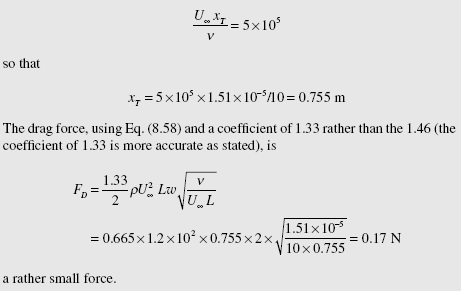
Atmospheric air at 20°C flows at 10 m/s over a smooth, rigid 2-m-wide, 4-m-long flat plate aligned with the flow. How long is the laminar portion of the boundary layer? Predict the drag force on the laminar portion on one side of the plate.
Solution
Assuming the air to free of high-intensity disturbances, use the critical Reynolds number to be 5 × 10⁵, i.e.,
Water at 20°C flows over a 2-m-long, 3-m-wide flat plate at 12 m/s. Estimate the shear velocity, the viscous wall-layer thickness, and the boundary-layer thick- ness at the end of the plate (assume a turbulent layer from the leading edge). Also, predict the drag force on one side of the plate.
Solution
The Reynolds number is Re = U∞ x/ν = 12 × 2 /10-6 = 2.4 × 10⁷.So, with n = 7 Eq. (8.64) provides
LAMINAR BOUNDARY-LAYER DIFFERENTIAL EQUATIONS
The laminar flow solution given in the preceding section was an approximate solution. In this section we will present a more accurate solution using the x-component Navier Stokes equation. It is, for horizontal plane flow (no z-variation),
We can simplify this equation and actually obtain a solution. First, recall that the boundary layer is very thin so that there is no pressure variation normal to the
boundary layer, i.e., the pressure depends on x only and it is the pressure at the wall from the potential flow solution. Since the pressure is considered known, the unknowns in Eq. (8.70) are u and v. The continuity equation
![]() also relates u and v. So, we have two equations and two unknowns. Consider Figs. 8.12 and 8.13; u changes from zero to U over the very small distance d, resulting in very large gradients in the y-direction, whereas u changes quite slowly in the x-direction (holding y fixed). Consequently, we conclude that
also relates u and v. So, we have two equations and two unknowns. Consider Figs. 8.12 and 8.13; u changes from zero to U over the very small distance d, resulting in very large gradients in the y-direction, whereas u changes quite slowly in the x-direction (holding y fixed). Consequently, we conclude that
The two acceleration terms on the left side of the equation are retained, since v may be quite small but the gradient ∂u/∂y is quite large. Equation (8.73) is the Prandtl boundary-layer equation.
For flow on a flat plate with dp/dx = 0, and in terms of the stream function y (recall that u = ∂ψ /∂ y and v = −∂ψ /∂ x), Eq. (8.73) takes the form
![image_thumb[5] image_thumb[5]](http://lh3.ggpht.com/-Nv_nmGTxLZ4/VGTzB7M7eOI/AAAAAAAA0CE/wyl0L4IEIEA/image_thumb%25255B5%25255D_thumb.png?imgmax=800) This equation appears more formidable than Eq. (8.74), but if we let
This equation appears more formidable than Eq. (8.74), but if we let
![image_thumb[6] image_thumb[6]](http://lh6.ggpht.com/-fo97tLJk5hg/VGTzEuZ_-GI/AAAAAAAA0CU/dIpxtHW0kLw/image_thumb%25255B6%25255D_thumb.png?imgmax=800) The numerical solution to the boundary-value problem is presented in Table 8.5. The last two columns allow the calculation of v and t0, respectively. We defined the
The numerical solution to the boundary-value problem is presented in Table 8.5. The last two columns allow the calculation of v and t0, respectively. We defined the
![image_thumb[7] image_thumb[7]](http://lh4.ggpht.com/-MFUhu0H7MDo/VGTzHRYagTI/AAAAAAAA0Ck/gnBmkRK_Jhk/image_thumb%25255B7%25255D_thumb.png?imgmax=800) boundary-layer thickness to be that thickness where u = 0.99U∞ and we observe that this occurs at h = 5. So, from this numerical solution,
boundary-layer thickness to be that thickness where u = 0.99U∞ and we observe that this occurs at h = 5. So, from this numerical solution,
Air at 30°C flows over a 2-m-wide, 4-m-long flat plate with a velocity of 2 m/s and dp/dx = 0. At the end of the plate, estimate (a) the wall shear stress, (b) the maximum value of v in the boundary layer, and (c) the flow rate through the boundary layer. Assume laminar flow over the entire length.
Solution
The Reynolds number is ![]() so laminar flow is reasonable.
so laminar flow is reasonable.
(a) The wall shear stress (this requires F ′′ at the wall) at x = 4 m is
(b) The maximum value of v requires the use of (h F ′ – F). Its maximum value occurs at the outer edge of the boundary layer and is 0.860. The maximum value of v is
1. Estimate the drag coefficient for air at 10°C flowing around a 4.1-cm-diameter golf ball traveling at 35 m/s.
(A) 0.25
(B) 0.86
(C) 0.94
(D) 1.2
2. A fluid flows by a flat circular disk with velocity V normal to the disk with Re > 103. Estimate the drag coefficient if the pressure is assumed constant over the face of the disk. Assume the pressure is zero on the backside.
(A) 1.1
(B) 1.0
(C) 0.9
(D) 0.8
3. Atmospheric air at 20°C is flowing at 10 m/s normal to a 10-cm-wide, 20-cm-long rectangular plate. The drag force is nearest
A) 2.95 N
(B) 2.41 N
(C) 1.76 N
(D) 1.32 N
4. A 20-cm-diameter smooth sphere is rigged with a strain gage calibrated to measure the force on the sphere. Estimate the wind speed in 20°C air if the gage measures 0.5 N.
(A) 21 m/s
(B) 25 m/s
(C) 29 m/s
(D) 33 m/s
5. A 2.2-m-long hydrofoil with chord length of 50 cm operates 40 cm below the water’s surface with an angle of attack of 4°. For a speed of 15 m/s, the lift is nearest
(A) 75 kN
(B) 81 kN
(C) 99 kN
(D) 132 kN
6. Estimate the takeoff speed for an aircraft with conventional airfoils if the aircraft with payload weighs 120 000 N and the effective wing area is
20 m2 assuming a temperature of 30°C. An angle of attack at takeoff of
8° is desired.
(A) 100 m/s
(B) 95 m/s
(C) 90 m/s
(D) 85 m/s
7. Find the associated stream function if the potential function is φ = 10 y in a potential flow.
(A) 10x
(B) 10y
(C) −10x
(D) −10y
8. A flow is represented by ψ = 10 ln(x2 + y2 ) . Find the pressure along the negative x-axis if atmospheric air is flowing and p = 0 at x = −∞.
(Α) −120/x2
(B) −160/x2
(C) −200/x2
(D) −240/x2
9. A uniform flow V = 10i m/s is superimposed on a doublet with strength 40 m3/s. The velocity distribution v (θ) on the cylinder is
(A) 10 sinθ
(B) 20 sinθ
(C) 40 sinθ
(D) 80 sinθ
10. A turbulent boundary layer is studied in a zero pressure-gradient flow on a flat plate. Atmospheric air at 20°C flows over the plate at 10 m/s. How far from the leading edge can turbulence be expected if the free-stream fluctuation intensity is low?
(A) 60 cm
(B) 70 cm
(C) 80 cm
(D) 90 cm
11. Given ![]() where
where ![]() and U∞ = 1 m/s. The drag force on one side of a 2-m-wide, 4-m-long plate, over which 20°C atmospheric air flows, is nearest (A) 0.013 N
and U∞ = 1 m/s. The drag force on one side of a 2-m-wide, 4-m-long plate, over which 20°C atmospheric air flows, is nearest (A) 0.013 N
(B) 0.024 N
(C) 0.046 N
(D) 0.067 N
12. A laminar boundary layer of 20°C water moving at 0.8 m/s exists on one side of a 2-m-wide, 3-m-long flat plate. At x = 3 m, vmax is nearest
(A) 0.008 m/s
(B) 0.006 m/s
(C) 0.0004 m/s
(D) 0.0002 m/s
Quiz No. 2
1. Estimate the drag coefficient for air at 0°C moving past a 10-cm-diameter, 4-m-high pole at 2 m/s.
2. Atmospheric air at 20°C is flowing at 10 m/s normal to a 10-cm-diameter, 80-cm-long smooth cylinder with free ends. Calculate the drag force.
3. A 220-cm-square sign is impacted straight on by a 50 m/s 10°C wind. If the sign is held by a single 3-m-high post imbedded in concrete, what moment would exist at the base of the post?
4. A sensor is positioned downstream a short distance from a 4-cm-diameter cylinder in a 20°C atmospheric airflow. It senses vortex shedding at a frequency of 0.16 Hz. Estimate the airspeed.
5. A 2000-kg airplane is designed to carry a 4000-N payload when cruising near sea level. For a conventional airfoil with an effective wing area of 25 m2, estimate the stall speed at elevation of 2000 m.
6. Find the associated potential function if the stream function is ψ = 20xy in a potential flow.
7. A flow is represented by ψ = 10 ln(x2 + y2 ) m2/s. Find the x-component of the acceleration at (−4, 0).
8. Locate any stagnation points in the flow represented by
9. A body is formed by the streamline that separates the source flow of strength q = 10π m2/s from a uniform flow parallel to the x-axis of 10 m/s. Locate the positive y-intercept of the body formed by the streamline that separates the source flow from the uniform flow.
10. Assume a linear velocity profile in a laminar boundary layer on a flat plate with a zero pressure gradient. Find d (x).
11. If the walls in a wind tunnel are parallel, the flow will accelerate due to the boundary layers on each of the walls. If a wind tunnel using 20°C atmospheric air is square, how should one of the walls be displaced outward for a zero pressure gradient to exist if U = 10 m/s? Assume turbulent flow.
12. Atmospheric air at 20°C flows over a 3-m-long and 2-m-wide flat plate at 16 m/s. Assume a turbulent flow from the leading edge and calculate drag force on one side of the plate.
13. A long cigar-shaped dirigible is proposed to take rich people on cruises.
It is proposed to be 1000 m long and 150 m in diameter. How much horsepower is needed to move the dirigible through sea-level air at 12 m/s if the drag on the front and rear is neglected. Use the drag coefficient of Eq. (8.67).









![image_thumb[1] image_thumb[1]](http://lh5.ggpht.com/-DhxYI1ZR55c/VGTy3m-K-3I/AAAAAAAA0BE/fQfD6wfmq5Y/image_thumb%25255B1%25255D_thumb.png?imgmax=800)
![image_thumb[2] image_thumb[2]](http://lh3.ggpht.com/-2o9p--1jMOA/VGTy6Pl2zRI/AAAAAAAA0BU/YpEpOtmNEVQ/image_thumb%25255B2%25255D_thumb.png?imgmax=800)
![image_thumb[4] image_thumb[4]](http://lh4.ggpht.com/-fciZRGTd08k/VGTy_OSzFzI/AAAAAAAA0B0/ucupY9N756o/image_thumb%25255B4%25255D_thumb.png?imgmax=800)
![image_thumb[8] image_thumb[8]](http://lh3.ggpht.com/-azB2FI53UCg/VGTzKPbqO5I/AAAAAAAA0C0/MRDd52-CiBM/image_thumb%25255B8%25255D_thumb.png?imgmax=800)
![image_thumb[9] image_thumb[9]](http://lh6.ggpht.com/-Oy6OiRVJ2KQ/VGTzPKhhqwI/AAAAAAAA0DU/BOL7rJpaeuo/image_thumb%25255B9%25255D_thumb.png?imgmax=800)
![image_thumb[11] image_thumb[11]](http://lh4.ggpht.com/-8sxNBCRdqo0/VGTzSKjXVSI/AAAAAAAA0Dk/liwoUqwBCWs/image_thumb%25255B11%25255D_thumb.png?imgmax=800)