Magnetic Forces
Magnetic fields exert forces on moving charges. If these charges are confined to wires then the fields can be thought of as exerting forces on current-carrying wires. The vector equation for the force is ![]()
where l is the length of the wire taken in the direction of the current. In most instances it is not necessary to do a formal vector cross product because the direction of the current and the magnetic field are perpendicular. The one instance where this becomes important is in considering the torque on a current-carrying wire. This problem is central to several topics and is taken up as a separate exercise.
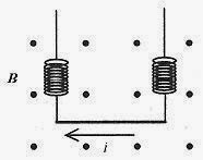
34-1 A typical problem illustrating the force on a current-carrying wire is the problem of a wire of 0.010kg and 1.0m in length suspended by springs in a B field of strength 30T directed out of the page. What current will cause zero tension in the springs?
Fig. 34-1
Solution: First consider the direction of the current. The force due to the magnetic field has to be up so the current has to be from right to left. With the right hand, form I × B with i in both directions to verify this conclusion. The value of the current that makes for zero tension in the springs occurs when the force due to the magnetic field balances gravity. This is a force-balance problem.
34-2 Another problem illustrating this force is a rod or bar resting on current-carrying rails with a perpendicular magnetic field. Take the field as 0.50 gauss (approximately the earth’s field) and the separation as 3.0m and calculate the current needed through the bar of mass 0.20kg with coefficient of friction 0.070 to make it slide along the rails.
Fig. 34-2
Solution: The orientation of current (either direction in the bar) and magnetic field is such that the force produced by the il × B will slide the bar along the rails. Verify this with the right-hand rule. The force opposing this sliding is μmg so this is a force-balance problem.
A Current-Carrying Loop in a B Field
The study of torque on a current-carrying loop leads to the definition of the magnetic moment of a circulating current, the understanding of the meter movement (voltmeter and current meter), and electric motors and generators. A loop of wire placed in a magnetic field and oriented as shown in Fig. 34-3 will have no torque or maximum torque, depending on the orientation (rotation) of the loop with respect to the magnetic field.
Fig. 34-3
As shown in the middle diagram the piece of wire on the right carrying a current, i, represented by the tail of the current arrow, has a force to the right (l × B) producing no torque. The piece of wire on the left produces a force to the left also producing no torque. In the diagram on the right the forces are in the same direction but for this orientation of the coil the torque is a maximum.
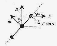
Figure 34-4 shows the torque for angles other than for zero or maximum torque. The torque is the component of this force at right angles to the line connecting the two sides of the coil times b/2 (the lever arm) times 2 (two wires).
Fig. 34-4
The appropriate component of the force is F sinα. The vector, m, the magnetic moment, is normal to the plane of the coil and points in the direction of the thumb when the fingers are curled naturally in the direction of the current in the coil. The angle between m and B is the same as the angle between force and lever arm. ![]() The product ab is the area,A, of the loop. The sin α term implies a cross product and if iA is taken as the magnitude of m, the magnetic moment, with the direction as defined in Fig. 34-4 then the vector equation for the torque is
The product ab is the area,A, of the loop. The sin α term implies a cross product and if iA is taken as the magnitude of m, the magnetic moment, with the direction as defined in Fig. 34-4 then the vector equation for the torque is ![]()
34-3 Find an expression for the torque on a circular coil of radius α carrying a current I placed at an angle to a magnetic field.
Fig. 34-5
Solution: The definition of the magnetic moment and the expression for the torque based on the magnetic moment is most convenient. The magnetic moment is m = I A = πa2I. The magnitude of the torque is T = mBsin α = πa2 IBsin α and the direction is the direction determined by m × B.
<><><><><><><><><><><><>
34-4 Find the maximum torque on a circular coil of 0.050m radius with current of 0.50A and in a magnetic field of 0.0050T.
Solution The maximum torque is![]()
<><><><><><><><><><><><>
34-5 The plane of a 10 turn rectangular loop of wire 3.0cm by 4.0cm carrying 2.0A is at an angle of 60° with respect to a magnetic field of 20 T. What is the torque on the loop in this position?
Solution: First calculate the magnetic moment noting that the current is not due to one loop but ten loops. m =I A = 10.2.0A.12×10-4 m2 = 2.4×10⁻² A.m2. Refer to Fig. 34-5 and note that if the angle between the plane of the coil and the magnetic field is 60°, then the angle between m and B is 30°, so the torque is ![]()
<><><><><><><><><><><><>
34-6 An interesting problem is to ask the question, “What dimensions of rectangle will produce maximum torque for the same length of wire?”
Solution: Take a rectangle with length l, width w,2 and perimeter equal to p=2l+2w. The perimeter relating l to w is the constraint in the problem. The torque is T = mB = I AB = IlwB. Before looking for a maximum we need to write l or w in terms of the constraint p.
Now take two derivatives of T with respect to w
The first derivative is zero (indicating a maximum or minimum) when p = 4w and putting this requirement in for p in the constraint equation (2l + 2w = 4w) requires that l = w. The rectangle must be a square. The second derivative is always negative indicating that the curve is everywhere concave down and that this point is a maximum.
d’Arsonval Meter Movement
A schematic of a d’Arsonval galvanometer is shown in Fig. 34-6. The torque on a loop in a magnetic field offset by the torque of a spiral spring as shown here is the basis for mechanical meter movements. Galvanometers are mid-reading meters. Current meters use parallel (with the coil) resistors to change the scale of the meter. Voltmeters use large series resistors to take the small currents necessary to activate the meter to measure voltage.
Fig. 34-6
The plane of the coil is parallel to the magnetic field so that a small current in the coil produces a torque on the coil which is offset by the torque of the spiral spring. With this arrangement, the rotation of the coil is proportional to the current. The external magnetic field (supplied by the permanent magnet) is curved (shaped) so the field is parallel to the plane of the coil through an angle of typically sixty degrees. Meter movements are rated as to how much current causes full scale deflection. A movement with a full scale deflection corresponding to 1.0μA is typical.
Energy Storage in Magnetic Materials
Magnetic dipoles placed in a magnetic field experience a torque. A simple model of a magnetic dipole is a molecule with a circulating current. These dipoles are rotated depending on the restoring torque of the material (structure). Picture a collection of magnetic dipolar molecules in a crystalline structure rotated by an external magnetic field thus stressing the structure. Consider the work done on a magnetic dipole by the application of an external magnetic field. This work is equivalent to the energy stored in the dipole-field combination.
The energy of the system is taken as zero when m and B are at right angles (α= 90°). The energy at a position α, analogous to both the electrical and mechanical relationship between torque, angle, and energy, is 
34-7 A coil of 5.0 × 8.0 cm dimensions and carrying a current of 0.0020A is rotated 45° by a 20T magnetic field from parallel to the plane of the field to an angle of 45° with respect to the field (see Fig. 34-5). Calculate the energy of the system.
Solution: The energy of the system is ![]() This is the energy stored in the system. An external agent would have to perform this amount of work to move the dipole (coil) back to parallel with the external magnetic field.
This is the energy stored in the system. An external agent would have to perform this amount of work to move the dipole (coil) back to parallel with the external magnetic field.


