The NAND Gate
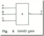
The NAND gate. Fig .6, performs the inverse logical function to the AND gate. The output of a NAND gate is at 0 only if all of the inputs to the gate are at 1. The truth table of 2-input and 3-input NAND gates are given by Table 8,6. The Boolean expressions for the two NAND gates are given by equations (8.6) and (8.7) respectively.
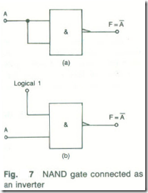
The NOT function can be produced using a NAND gate in either of two different ways. Referring to the truth table of the 2-input NAND gate it can be seen that:
(a) if the inputs A and B are connected together so that A = B, Fig . 7(a), the output will always be inverted, and
(b) if either input is held at the logical 1 voltage level, Fig. 7(b), the output will always be NOT the logical state of the other input.
There are a number of NAND gales available in the various TTL sub-families:
7400 quad 2-input NAND gates
7410 triple 3-input NAND gates
7420 dual 4-input.NAND gates
7430 single 8-input NAND gate.
The NOR Gale
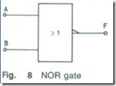
The NOR gate. Fig. 8, performs the inverse of the logical OR function. This means that the output F of a NOR gate is at logical 1 only when all of its inputs are at logical 0. The truth tables for both 2-input and 3-input NOR gates are given by Table 7. The Boolean expressions for the two gates are given by
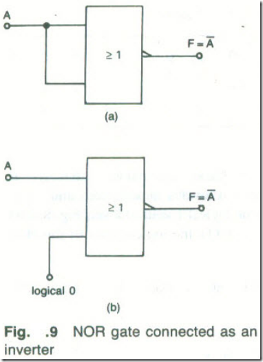
The NOT function can be generated by a NOR gate if either (a) both its input terminals are connected together, Fig. 9(a), or (b) one input is connected to the logical 0 voltage level, Fig .9(b).
The NOR gates in the TTL family are:
7402 quad 2-input NOR gates
7427 triple 3-input NOR gates.
Table 7 2-input and 3-input NOR gates
Example 2
The inputs to a 3-input NOR gate are two at binary 0 and the third at binary
1. What is the logical state of the output of the gate?
Solution
![]() so if any of the inputs is at 0 the output will be at 0 .
so if any of the inputs is at 0 the output will be at 0 .
Therefore, F = 0 (Ans.)
Exclusive-OR Gate
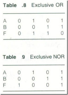
The exclusive-OR gate has two input terminals and one output terminal. The output will be at binary I whenever the states of the two inputs are not the same. If both inputs are at 1 or both inputs are at 0 the output of the gate is at 0. The truth table of an exclusive-OR gate is given by Table 8, and the Boolean equation that describes the operation of the gate is given by
This is often written as
Exclusive-NOR Gate
An exclusive-NOR gate has two input terminals and one output terminal. The output will be at binary 1 only when both inputs are at the same logic state. Whenever the inputs are at different logical states the output will be at logic 0. The truth table of an exclusive-NOR gate is given by Table .9 and the Boolean expression for the gate is given by equation
This is often written as
Example 3
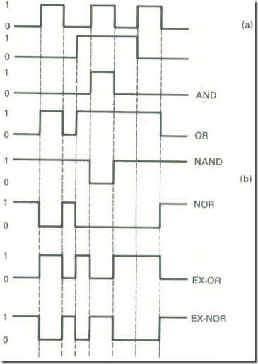
The waveforms given in Fig .10(a) are applied to the input terminals of a 2-input gate. Draw the output waveform if the gate is (a) AND; (b) OR; (c) NAND; (d) NOR; NOR; (e) exclusive-OR or (f) exclusive-NOR.
solution
The output waveforms are shown by fig .10(b)
Digital Integrated Circuits
In practice, the vast majority of the gates employed in digital circuitry are members of either the TTL or the CMOS logic families. Some TTL examples, showing IC package pin connections are given in Fig .11(a). The TTL family includes the standard 74 series, the low-power Schottky 74LS series, the advanced Schottky 74AS series and , the advanced low-power Schottky 74ALS series. The examples given in Fig. 11(a) have representatives in each series.
The CMOS logic family includes the standard 4000 series, the high-speed HCMOS series and the advanced CMOS series. Some examples of the 4000 series gates are given by Fig.11(b).
It is normally preferable for economic reasons for one circuit to employ ICs from only one logic family. The choice of the logic family is based on a number of factors, such as power dissipation and speed of operation.


