Introduction
The superposition theorem states:
‘In any network made up of linear impedances and containing more than one source of e.m.f. the resultant current flowing in any branch is the phasor sum of the currents that would flow in that branch if each source were considered separately, all other sources being replaced at that time by their respective internal impedances’
Using the Superposition Theorem
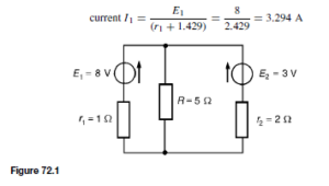
The superposition theorem, which was introduced in chapter 53 for d.c. circuits, may be applied to both d.c. and a.c. networks. A d.c. network is shown in Figure 72.1 and will serve to demonstrate the principle of application of the superposition theorem.
To find the current flowing in each branch of the circuit, the following six-step procedure can be adopted:
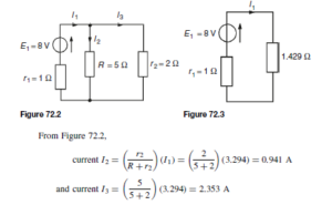
(i) Redraw the original network with one of the sources, say E2, removed and replaced by r2 only, as shown in Figure 72.2.
(ii) Label the current in each branch and its direction as shown in Figure 72.2, and then determine its value. The choice of current direction for I1 depends on the source polarity which, by convention, is taken as flowing from the positive terminal as shown.
R in parallel with r2 gives an equivalent resistance of ![]() as shown in the equivalent network of Figure 72.3.
as shown in the equivalent network of Figure 72.3.
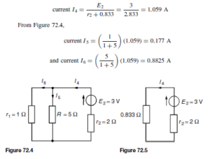
 (iii) Redraw the original network with source E1 removed and replaced by r1 only, as shown in Figure 72.4.
(iv) Label the currents in each branch and their directions as shown in Figure 72.4, and determine their values.
R and r1 in parallel gives an equivalent resistance of ![]() as shown in the equivalent network of Figure 72.5.
as shown in the equivalent network of Figure 72.5.
From Figure 72.5,
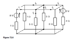
(v) Superimpose Figure 72.2 on Figure 72.4, as shown in Figure 72.6.
(vi) Determine the algebraic sum of the currents flowing in each branch. (Note that in an a.c. circuit it is the phasor sum of the currents that is required). From Figure 72.6, the resultant current flowing through the 8 V source is given by![]() (discharging, i.e. flowing from the positive terminal of the source).
(discharging, i.e. flowing from the positive terminal of the source).
The resultant current flowing in the 3 V source is given by I3 – I4 =2.353 – 1.059 = 1.29 A (charging, i.e. flowing into the positive terminal of the source).
The resultant current flowing in the 5 Q resistance is given by I2 C I5 =0.941 C 0.177 = 1.12
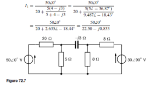
Using the superposition theorem in Figure 72.7 will demonstrate its use with an a.c. network.
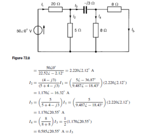
(i) The network is redrawn with the 306 90° V source removed, as shown in Figure 72.8.
(ii) Currents I1 to I5 are shown labelled in Figure 72.8. From Figure 72.8, two 8 Q resistors in parallel give an equivalent resistance of 4 Q. Hence
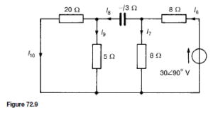
(iii) The original network is redrawn with the 506 0° V source removed, as shown in Figure 72.9.
(iv) Currents I6 to I10 are shown labelled in Figure 72.9. From Figure 72.9, 20 Q in parallel with 5 Q gives an equivalent resistance of: ![]() 4
4
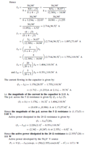
Total power developed, P = P1 + P2 = 117.1 + 74.7 = 191.8 W
(This value may be checked by summing the I2R powers dissipated in the four resistors).
The superposition theorem is straightforward to apply, but is lengthy.
The´venin’s and Norton’s theorems (described in chapter 73) produce the same results more quickly.

