Mesh-current Analysis
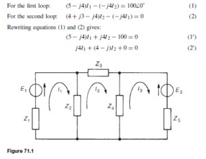
Mesh-current analysis is merely an extension of the use of Kirchhoff’s laws, explained in chapter 70. Figure 71.1 shows a network whose circulating cur- rents I1, I2 and I3 have been assigned to closed loops in the circuit rather than to branches. Currents I1 , I2 and I3 are called mesh-currents or loop-currents.
In mesh-current analysis the loop-currents are all arranged to circulate in the same direction (in Figure 71.1, shown as clockwise direction). Kirchhoff’s second law is applied to each of the loops in turn, which in the circuit of Figure 71.1 produces three equations in three unknowns that may be solved for I1 , I2 and I3 . The three equations produced from Figure 71.1 are:
The branch currents are determined by taking the phasor sum of the mesh currents common to that branch. For example, the current flowing in impedance Z2 of Figure 71.1 is given by (I1 ð I2) phasorially. The method of mesh-current analysis is often called Maxwell’s theorem.
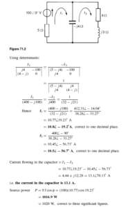
For example, for the a.c. network shown in Figure 71.2, using mesh- current analysis:
Nodal Analysis
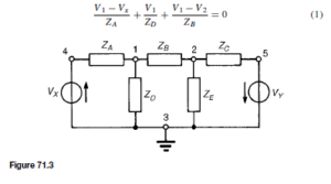
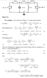
A node of a network is defined as a point where two or more branches are joined. If three or more branches join at a node, then that node is called a principal node or junction. In Figure 71.3, points 1, 2, 3, 4 and 5 are nodes, and points 1, 2 and 3 are principal nodes.
A node voltage is the voltage of a particular node with respect to a node called the reference node. If in Figure 71.3, for example, node 3 is chosen as the reference node then V13 is assumed to mean the voltage at node 1 with respect to node 3 (as distinct from V31 ). Similarly, V23 would be assumed to mean the voltage at node 2 with respect to node 3, and so on. However, since the node voltage is always determined with respect to a particular chosen reference node, the notation V1 for V13 and V2 for V23 would always be used in this instance.
The object of nodal analysis is to determine the values of voltages at all the principal nodes with respect to the reference node, for example, to find voltages V1 and V2 in Figure 71.3. When such voltages are determined, the currents flowing in each branch can be found.
Kirchhoff’s current law is applied to nodes 1 and 2 in turn in Figure 71.3 and two equations in unknowns V1 and V2 are obtained which may be simultaneously solved using determinants.
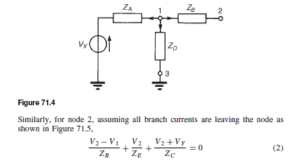
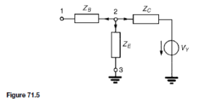
The branches leading to node 1 are shown separately in Figure 71.4. Let us assume that all branch currents are leaving the node as shown. Since the sum of currents at a junction is zero,
In equations (1) and (2), the currents are all assumed to be leaving the node. In fact, any selection in the direction of the branch currents may be made –the resulting equations will be identical. (For example, if for node 1 the current flowing in ZB is considered as flowing towards node 1 instead of away, then the equation for node 1 becomes
which if rearranged is seen to be exactly the same as equation (1)). Rearranging equations (1) and (2) gives:
Equations (3) and (4) may be solved for V1 and V2 by using determinants. Current equations, and hence voltage equations, may be written at each principal node of a network with the exception of a reference node. The number of equations necessary to produce a solution for a circuit is, in fact, always one less than the number of principal nodes.
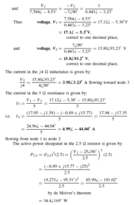
Thus the magnitude of the active power dissipated in the 2.5 Z resistance is 34.4 W.
Whether mesh-current analysis or nodal analysis is used to determine currents in circuits depends on the number of loops and nodes the circuit contains. Basically, the method that requires the least number of equations is used.


