Maximum Power Transfer Theorems
A network that contains linear impedances and one or more voltage or current sources can be reduced to a The´venin equivalent circuit as shown in chapter 73. When a load is connected to the terminals of this equivalent circuit, power is transferred from the source to the load.
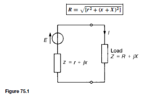
A Thevenin equivalent circuit is shown in Figure 75.1 with source internal impedance, z D (r C jx) Q and complex load Z D (R C jX) Q.
The maximum power transferred from the source to the load depends on the following four conditions:
1. When the load is purely resistive (i.e. X D 0) and adjustable, maximum power transfer is achieved when
2.When both the load and the source impedance are purely resistive (i.e. X = x = 0), maximum power transfer is achieved when R = r (This is, in fact, the d.c. condition explained in Chapter 53, page 340).
3. When the load resistance R and reactance X are both independently adjustable, maximum power transfer is achieved when
4. When the load resistance R is adjustable with reactance X fixed, maximum power transfer is achieved when
The maximum power transfer theorems are primarily important where a small source of power is involved — such as, for example, the output from a telephone system.
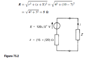
For example, for the circuit shown in Figure 75.2 the load impedance Z is a pure resistance. The value of R for maximum power to be transferred from the source to the load is determined as follows:
From condition 1, maximum power transfer occurs when R D jzj, i.e. when
Thus maximum power delivered, P = I2 R = (2.683)2 (25) = 180 W In another example, if the load impedance Z in Figure 75.2 consists of variable resistance R and variable reactance X, the value of Z that results in maximum power transfer is determined as follows:
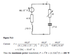
and maximum power delivered to the load, P = I2R = (4)2 (15) = 240 W In a further example, in the network shown in Figure 75.3 the load consists
of a fixed capacitive reactance of 7 Q and a variable resistance R. The value of R for which the power transferred to the load is a maximum is determined as follows:
From condition (4), maximum power transfer is achieved when
Impedance Matching
It is seen from the previous section that when it is necessary to obtain the maximum possible amount of power from a source, it is advantageous if the circuit components can be adjusted to give equality of impedances. This adjustment is called ‘impedance matching’ and is an important consideration in electronic and communications devices, which normally involve small amounts of power. Examples where matching is important include coupling an aerial to a transmitter or receiver, or coupling a loudspeaker to an amplifier.
The mains power supply is considered as infinitely large compared with the demand upon it, and under such conditions it is unnecessary to consider the conditions for maximum power transfer. With transmission lines (see chapter 83), the lines are ‘matched’, ideally, i.e. terminated in their characteristic impedance.
With d.c. generators, motors or secondary cells, the internal impedance is usually very small and in such cases, if an attempt is made to make the load impedance as small as the source internal impedance, overloading of the source results.
A method of achieving maximum power transfer between a source and a load is to adjust the value of the load impedance to match the source impedance,
which can be done using a ‘matching-transformer’.
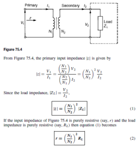
A transformer is represented in Figure 75.4 supplying a load impedance ZL . Small transformers used in low power networks are usually regarded as ideal (i.e. losses are negligible), such that
(This is the case introduced in chapter 60, page 419)
Thus by varying the value of the transformer turns ratio, the equivalent input impedance of the transformer can be ‘matched’ to the impedance of a source to achieve maximum power transfer.
For example, a generator has an output impedance of (450 + j60) Q. The turns ratio of an ideal transformer necessary to match the generator to a load of (40 + j19) Q for maximum transfer of power is determined as follows:
Let the output impedance of the generator be z, where z = (450 + j60) Q or 453.986 7.59° Q and the load impedance be ZL , where ZL = (40 + j19) Q
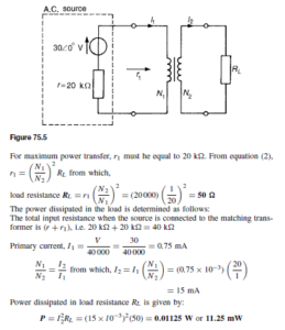
In another example, let an ac. source of 306 0° V and internal resistance 20 kQ be matched to a load by a 20 : 1 ideal transformer. The network diagram is shown in Figure 75.5. The value of the load resistance for maximum power transfer is determined as follows:

