Introduction
The laws that determine the currents and voltage drops in d.c. networks are:
(a) Ohm’s law (see chapter 40), (b) the laws for resistors in series and in parallel (see chapter 43), and (c) Kirchhoff’s laws. In addition, there are a number of circuit theorems that have been developed for solving problems in electrical networks. These include:
(i) the superposition theorem
(ii) The´venin’s theorem
(iii) Norton’s theorem
(iv) the maximum power transfer theorem
Kirchhoff’s Laws
Kirchhoff’s laws state:
(a) Current Law. At any junction in an electric circuit the total current flowing towards that junction is equal to the total current flowing away from the junction, i.e.
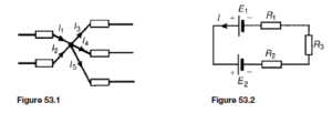
Thus, referring to Figure 53.1:
(b) Voltage Law. In any closed loop in a network, the algebraic sum of the voltage drops (i.e. products of current and resistance) taken around the loop is equal to the resultant e.m.f. acting in that loop.
Thus, referring to Figure 53.2:
(Note that if current flows away from the positive terminal of a source, that source is considered by convention to be positive. Thus moving anticlockwise around the loop of Figure 53.2, E1 is positive and E2 is negative)
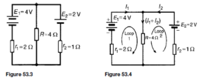
For example, using Kirchhoff’s laws to determine the currents flowing in each branch of the network shown in Figure 53.3, the procedure is as follows:
1. Use Kirchhoff’s current law and label current directions on the original circuit diagram. The directions chosen are arbitrary, but it is usual, as a starting point, to assume that current flows from the positive terminals of the batteries. This is shown in Figure 53.4 where the three branch currents are expressed in terms of I1 and I2 only, since the current through R is (I1 + I2)
2. Divide the circuit into two loops and apply Kirchhoff’s voltage law to
each. From loop 1 of Figure 53.4, and moving in a clockwise direction as indicated (the direction chosen does not matter), gives
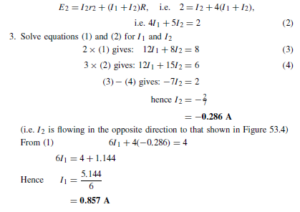
From loop 2 of Figure 53.4, and moving in an anticlockwise direction as indicated (once again, the choice of direction does not matter; it does not have to be in the same direction as that chosen for the first loop), gives:
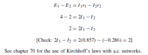
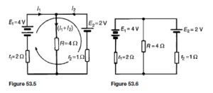
Note that a third loop is possible, as shown in Figure 53.5, giving a third equation which can be used as a check:
The Superposition Theorem
The superposition theorem states:
In any network made up of linear resistances and containing more than one source of e.m.f., the resultant current flowing in any branch is the algebraic sum of the currents that would flow in that branch if each source was considered separately, all other sources being replaced at that time by their respective internal resistances.
For example, to determine the current in each branch of the network shown in Figure 53.6, using the superposition theorem the procedure is as follows:
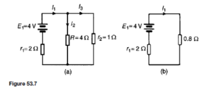
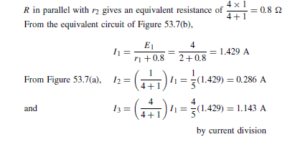
1. Redraw the original circuit with source E2 removed, being replaced by r2 only, as shown in Figure 53.7(a)
2. Label the currents in each branch and their directions as shown in Figure 53.7(a) and determine their values. (Note that the choice of current
directions depends on the battery polarity, which, by convention is taken as flowing from the positive battery terminal as shown)
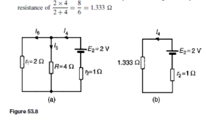
3. Redraw the original circuit with source E1 removed, being replaced by r1 only, as shown in Figure 53.8(a)
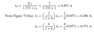
4. Label the currents in each branch and their directions as shown in Figure 53.8(a) and determine their values. r1 in parallel with R gives an equivalent
From the equivalent circuit of Figure 53.8(b),
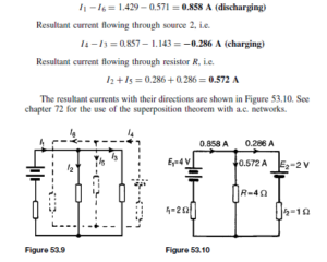
5. Superimpose Figure 53.8(a) on to Figure 53.7(a) as shown in Figure 53.9.
6. Determine the algebraic sum of the currents flowing in each branch.
Resultant current flowing through source 1, i.e.
General d.c. Circuit Theory
The following points involving d.c. circuit analysis need to be appreciated before proceeding with problems using The´venin’s and Norton’s theorems:
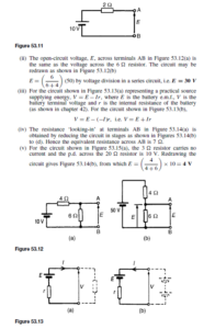
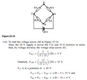
(i) The open-circuit voltage, E, across terminals AB in Figure 53.11 is equal to 10 V, since no current flows through the 2 Q resistor and hence no voltage drop occurs.
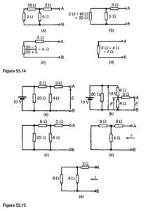
(vi) If the 10 V battery in Figure 53.15(a) is removed and replaced by a short-circuit, as shown in Figure 53.15(c), then the 20 Q resistor may be removed. The reason for this is that a short-circuit has zero resistance, and 20 Q in parallel with zero ohms gives an equivalent resistance of i.e. 0 Q. The circuit is then as shown in Figure 53.15(d), which is redrawn in Figure 53.15(e). From Figure 53.15(e), the equivalent resistance across AB,
Hence the voltage between AB is VA Ł VB D 15 Ł 4 D 11 V and cur- rent would flow from A to B since A has a higher potential than B.
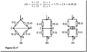
(viii) In Figure 53.17(a), to find the equivalent resistance across AB the circuit may be redrawn as in Figures 53.17(b) and (c). From Figure 53.16(c), the equivalent resistance across
The´venin’s Theorem
The´venin’s theorem states:
The current in any branch of a network is that which would result if an e.m.f. equal to the p.d. across a break made in the branch, were introduced into the branch, all other e.m.f.’s being removed and represented by the internal resistances of the sources.
The procedure adopted when using The´venin’s theorem is summarised below. To determine the current in any branch of an active network (i.e. one containing a source of e.m.f.):
(i) remove the resistance R from that branch,
(ii) determine the open-circuit voltage, E, across the break,
(iii) remove each source of e.m.f. and replace them by their internal resistances
and then determine the resistance, r, ‘looking-in’ at the break,
(iv) determine the value of the current from the equivalent circuit shown in
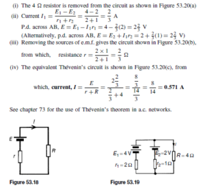
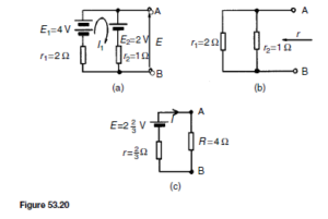
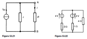
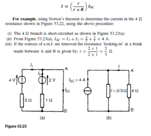
For example, using The´venin’s theorem to determine the current in the 4 Q resistor shown in Figure 53.19, using the above procedure:
Constant Current Source
A source of electrical energy can be represented by a source of e.m.f. in series with a resistance. In the above section, the The´venin constant-voltage source consisted of a constant e.m.f. E in series with an internal resistance r. However this is not the only form of representation. A source of electrical energy can also be represented by a constant-current source in parallel with a resistance. It may be shown that the two forms are equivalent. An ideal constant-voltage generator is one with zero internal resistance so that it supplies the same voltage to all loads. An ideal constant-current generator is one with infinite internal resistance so that it supplies the same current to all loads.
Note the symbol for an ideal current source (BS 3939,1985), shown in Figure 53.21.
Norton’s Theorem
Norton’s theorem states:
The current that flows in any branch of a network is the same as that which would flow in the branch if it were connected across a source of electrical energy, the short-circuit current of which is equal to the current that would flow in a short-circuit across the branch, and the internal resistance of which is equal to the resistance which appears across the open-circuited branch terminals.
The procedure adopted when using Norton’s theorem is summarised below.
To determine the current flowing in a resistance R of a branch AB of an active network:
(i) short-circuit branch AB
(ii) determine the short-circuit current ISC flowing in the branch
(iii) remove all sources of e.m.f. and replace them by their internal resistance (or, if a current source exists, replace with an open-circuit), then determine the resistance r, ‘looking-in’ at a break made between A and B
(iv) determine the current I flowing in resistance R from the Norton equivalent network shown in Figure 53.21, i.e.
(iv) From the Norton equivalent network shown in Figure 53.23(b) the current in the 4 Q resistance is given by:
See chapter 73 for the use of Norton’s theorem in a.c. networks.
The´venin and Norton Equivalent Networks
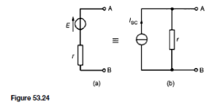
The The´venin and Norton networks shown in Figure 53.24 are equivalent to each other. The resistance ‘looking-in’ at terminals AB is the same in each of the networks, i.e. r
If terminals AB in Figure 53.24(a) are short-circuited, the short-circuit current is given by
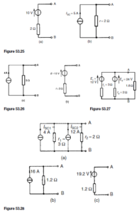
. If terminals AB in Figure 53.24(b) are short-circuited, the short-circuit current is ISC. For the circuit shown in Figure 53.24(a) to be equivalent to the circuit in Figure 53.24(b) the same short-circuit current must flow. Thus ISC = r For example, the circuit of Figure 53.25(a) is equivalent to the circuit of Figure 53.25(b).
Similarly, the circuit of Figure 53.26(a) is equivalent to the circuit of Figure 53.26(b).
In another example, the circuit to the left of terminals AB in Figure 53.27 is converted to an equivalent The´venin circuit as follows:
For the branch containing the 12 V source, converting to a Norton equivalent circuit gives
For the branch containing the 24 V source, converting to a Norton equivalent circuit gives
Thus Figure 53.28(a) shows a network equivalent to Figure 53.27.
From Figure 53.28(a) the total short-circuit current is 4 C 12 D 16 A and
Thus Figure 53.28(a) simplifies to Figure 53.28(b).
The open-circuit voltage across AB of Figure 53.28(b), E= (16)(1.2) = 19.2 V, and the resistance ‘looking-in’ at AB is 1.2 Q. Hence the The´venin equivalent circuit is as shown in Figure 53.28(c).
When the 1.8 Q resistance is connected between terminals A and B of Figure 53.28(c), the current I flowing is given by: ![]()
Maximum Power Transfer Theorem
The maximum power transfer theorem states:
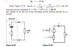
The power transferred from a supply source to a load is at its maximum when the resistance of the load is equal to the internal resistance of the source. Hence, in Figure 53.29, when R = r the power transferred from the source to the load is a maximum.
For example, a d.c. source has an open-circuit voltage of 30 V and an internal resistance of 1.5 Q as shown in Figure 53.30.
From the maximum power transfer theorem, for maximum power dissipation,

