speaker
The term speaker is a diminution of loudspeaker. The full word is now so rarely used, some catalogs do not recognize it as a search term. This encyclopedia acknowledges contemporary usage by using speaker rather than loudspeaker.
A fully assembled consumer product can be referred to as a “speaker,” but it also contains one or more individual components that are described as “speakers.” To resolve this ambiguity, referring to the components as drivers is helpful, but this practice can create more ambiguity because other types of components are also called “drivers.” The only real guide to the meaning of speaker is the context in which it is used.
For the purposes of this entry, a speaker is a sound reproduction device, distinguished from a typical electromagnetic transducer by being larger and more powerful, with a more linear frequency response. A transducer may be used as a noise-creating device to provide an alert, informing the user of the status of a piece of equipment. Because some speakers have been miniaturized for use in handheld products, they may be used as transducers, allowing some overlap between the two categories.
Because this encyclopedia assigns more emphasis to electronic components than to consumer products, this entry provides only a superficial overview of fully assembled speakers, and deals more with the drivers inside them, their principles of operation, and the general topic of sound reproduction.
What It Does
A speaker converts fluctuations of an electric signal into pressure waves that the human ear per- ceives as sound. It can be used for entertainment purposes or to provide information in the form of spoken words or distinctive sounds (as in the case of a miniature speaker in a cellular phone, playing a ring tone).
The internationally accepted schematic symbol for a speaker is shown in Figure 30-1.
Figure 30-1. Only one symbol exists to represent a speaker. This is it.
How It Works
For a summary of basic concepts and terminology relating to sound and its reproduction, see “Audio Basics” on page 261 in the previous entry.
Construction
A speaker contains a diaphragm or cone with a coil attached to it. Fluctuations of current through the coil interact with a permanent mag- net, causing the speaker to emit pressure waves that are proportionate with the current. The de- sign is similar in concept to that of a headphone, shown diagrammatically in Figure 29-3. The primary difference is that a speaker of around 2” or more will use a cone rather than a flat diaphragm. The cone shape is more rigid and creates a more directional sound.
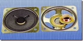
A 2” speaker rated for 1/4W with a 63Ω coil is shown in Figure 30-2, undamaged on the left but with its cone cut out on the right. The neck of the cone, which is normally inserted in the circular groove in the speaker magnet, is shown with the inductive coil wrapped around it.
Figure 30-2. On the left is a 2” speaker. On the right, its cone has been cut away to reveal the magnet, with a circular groove in it. The neck of the cone, which normally slides into the groove, is shown removed.
A speaker with a cone 4” in diameter is shown from the rear in Figure 30-3.
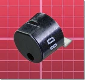
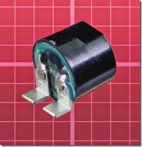
A miniature surface-mount speaker is shown from the front and from the rear in Figures 30-4 and 30-5. It measures just under 0.4” diameter and was made for Motorola. Its power rating is 50mW.
Figure 30-3. The back side of a speaker with a cone measuring approximately 4” in diameter. Its magnet is the large round section that is uppermost. This unit is rated for 4W and has an impedance of 8Ω.
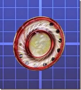
A speaker designed for a cellular phone is shown in Figure 30-6. Note the close resemblance in de- sign to the driver used in an earbud, shown in Figure 29-6 in the previous entry.
In the past, speaker cones were made from tough, fibrous paper. Modern cones are more likely to be plastic, especially in small sizes.
Figure 30-4. Front view of a surface-mount speaker measuring less than 0.4” diameter.
Figure 30-5. Rear view of the speaker shown in the previous figure.
Figure 30-6. A miniature speaker measuring slightly more than 1/2” diameter and only 0.13” thick, designed for use in a cellular phone. It has an impedance of 150Ω.
Multiple Drivers
Generally speaking, a large-diameter speaker cone is more effective than a small cone at moving the greater volumes of air associated with re- production of bass notes. However, the inertia of a large cone impairs its ability to vibrate at high frequencies.
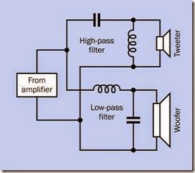
To address this problem, a large speaker and a small speaker often share a single enclosure. A crossover network using coils and capacitors pre- vents low frequencies from reaching the small speaker and high frequencies from reaching the large speaker. The basic principle is shown in the simplified schematic in Figure 30-7.
Figure 30-7. The basic principle of a crossover network.
Because the crossover network must be “tuned” to match the characteristics of the speakers, and because the combined sound pressure of the speakers must be relatively consistent over a wide range of frequencies, an actual network usually includes additional components.
Because the audio output from an amplifier consists of alternating current, polarized capacitors cannot be used. Polyester capacitors are common.
The small speaker in a pair is known as a tweeter while the large speaker is a woofer. Although these appellations were whimsically coined, they have endured.
More than two speakers may be combined in an enclosure, in a wide variety of configurations.
Venting
A speaker radiates pressure waves from the back side of its cone as well as from the front, and be- cause the waves from front and back are opposite in phase, they will tend to cancel each other out.
In a miniature speaker, this problem can be ad- dressed simply by sealing the section of the en- closure at the rear. For larger components, a more efficient enclosure can be designed with a vent or reflex port at the front. Pressure waves from the back of the speaker are diverted over a sufficient distance inside the cabinet so that by the time they emerge through the port, they are approximately in phase with low frequencies from the front of the speaker, although the back wave will lag the front wave by one wavelength.
This design is referred to as a bass-reflex enclosure, and was almost universal in high-fidelity components until amplifiers became increasing- ly powerful during the 1960s. At that point, Acoustic Research, located in Massachusetts, marketed a product line in which speaker enclosures were sealed, the argument being that when an amplifier can deliver 100W per channel, efficiency is no longer an issue, and a sealed en- closure can eliminate compromises associated with a bass-reflex design.
Acoustic Research referred to their concept as “air suspension,” as the cushion of air in the sealed cavity helped to protect the speaker by limiting its excursion. This configuration is now often referred to as a closed-box speaker. Some audiophiles argue that it must always be inherently superior to a bass-reflex design, partly because of the one-wavelength lag time associated with a reflex port. However, as in many aspects of sound reproduction, the debate is inconclusive.
Resonance
The enclosure for a speaker will tend to have a dominant resonant frequency. This should be lower than the lowest frequency that the speaker will reproduce; otherwise, the resonance will emphasize some frequencies relative to others, creating unwanted peaks in the response.
One reason why high-quality speakers tend to be physically heavy is to reduce their resonant frequency. A modern Thiel speaker assembly, for instance, uses a front panel of particle board that is a full 2” thick. However, heavy enclosures are expensive to transport and inconvenient to locate or relocate in the home.
To address this problem, a tweeter and a woofer can be mounted in separate boxes. The enclo- sure for the tweeter can be very small, light- weight, and suitable for placement on a shelf, while the heavy box for the woofer can go on the floor. Human senses have difficulty locating the source of low-frequency sound, so the woofer can be located almost anywhere in a room. In fact, its single speaker can serve both stereo channels.
This configuration has become the default for computer speakers. It is also used in home- theater systems, where the woofer has now be- come a subwoofer capable of very low frequency reproduction.
Miniature Speakers
If an electronics project has an audio output, and the circuit board will be sharing an enclosure with a small speaker, the size of the box and the material from which it is fabricated will affect the sound quality significantly. A box made from thin hardwood may add resonance that sounds pleasing, if the speaker is being used just for sim- ple electronic tones. By comparison, a metal box may sound “tinny.” A box fabricated from a plastic such as ABS will be relatively neutral, provided the plastic is reasonably thick (1/4” being preferable).
Variants
Electrostatic Speaker
The principle of an electrostatic speaker is the same as that of an electrostatic headphone. A charged membrane is stretched between two grids in front of it and behind it that act as electrodes. Because the membrane is so light, it responds with very little latency, and its large sur- face area creates a diffused sound that many audiophiles find pleasing. However, a high voltage is required to drive electrostatic speakers, and they are not cheap.
Powered Speakers
A unit containing its own driver electronics is referred to as a powered speaker, and is used almost universally with desktop computers, because the computer itself does not contain a power amplifier. Powered speakers may also enable a more versatile crossover network.
A subwoofer may have its own amplifier allowing control of the cutoff frequency above which the speaker will not attempt to reproduce sound. The electronics can include protection for a speaker against being overdriven.
Wireless Speakers
A wireless link between a stereo receiver and its speakers will eliminate the speaker wires that are normally necessary. However, the speakers themselves must be powered, and will have to be wired to electric outlets.
Innovative Designs
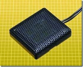
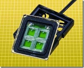
The need for small speakers in consumer products such as laptop computers has encouraged innovative designs. The speaker in Figure 30-8 is just 1” square, and its shape is easier to accommodate in a small product than the traditional circular speaker. In Figure 30-9, the interior of the same speaker shows that inductive coils are ap- plied to a square plastic diaphragm.
Figure 30-8. A speaker 1” square, suitable for use with a small electronic device.
Figure 30-9. The speaker from the previous figure, opened to show its inductive coils applied to a square plastic diaphragm.
Values
The typical impedance for speakers in audio systems is 8Ω. Small speakers may have a higher impedance, which can be useful when driving them from devices that have limited power, such as a TTL-type 555 timer.
In the United States, the diameter of a circular speaker is usually expressed in inches. Speakers larger than 12” are rare for domestic use. A 4” speaker used to be considered minimal because of its limited low-end frequency response, but much smaller speakers have become common in portable devices.
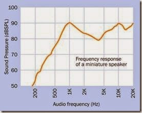
The low-end frequency response of a miniature loudspeaker designed to be surface-mounted on a circuit board will be very poor. The graph in Figure 30-10 was derived from data supplied by the manufacturer.
Figure 30-10. Frequency response for a speaker measuring 15mm x 15mm x 5mm. Small dimensions and lack of an enclosure result in a negligible low-end response.
Power rating for speakers is in watts, measured on a root-mean-square (RMS) basis.
Sensitivity is measured in decibels, at a distance of one meter, while a speaker is reproducing a single constant tone with a power input of 1W. A speaker assembly designed for undemanding home use may be rated at 85dB to 95dB.
Efficiency is a measure of sound power output divided by electrical power input. A value of 1% is typical.
What Can Go Wrong
Damage
As is the case with headphones, the most common problem affecting a speaker is damage caused by overdriving it. Because a low frequency requires larger excursions of a speaker cone to transmit an amount of energy comparable to that of a high frequency, loud bass notes can be hazardous to the cone. On the other hand, if an amplifier generates distortion (perhaps because it, too, is being overdriven), the harmonics cre- ated by the distortion can damage high- frequency speakers.
Magnetic Field
Even a small speaker (measuring 2” or less) con- tains a magnet that is sufficiently powerful to cause problems if it is in close proximity to other components, especially if sensors such as reed switches or Hall-effect switches are being used. Initial circuit testing should be done with the speaker as far away as possible, to eliminate it as a source of interference.
Vibration
Solder joints will be stressed if they are subjected to low-frequency vibration from a speaker. Loose parts may rattle, and parts that are bolted into place may become unbolted. The speaker itself may become loose. Thread-locker such as Loc- Tite should be applied to nuts before they are tightened.


