neon bulb
The terms neon bulb, neon indicator, and neon lamp tend to be used interchangeably. In this encyclopedia, a neon bulb is defined as a glass capsule containing two electrodes in neon gas (or a combination of gases in which neon is present). A neon lamp is an assembly containing a neon bulb, usually using a plastic tube with a tinted transparent cap at one end. A neon indicator is a miniature neon lamp that is usually panel-mounted.
Large-scale neon tubes used in signage are not included in this encyclopedia.
What It Does
When voltage is applied between two electrodes inside a neon bulb, the inert gas inside the bulb emits a soft red or orange glow. This color may be modified by using a tinted transparent plastic cap, known as a lens, in a neon lamp assembly.
A neon bulb is usually designed for a power sup- ply of 110V or higher. It functions equally well with alternating or direct current.
The schematic symbols in Figure 19-1 are commonly used to represent either a neon bulb or a neon lamp. They are all functionally identical. The black dot that appears inside two of the symbols indicates that the component is gas filled. The position of the dot inside the circle is arbitrary. Even though all neon bulbs are gas filled, the dot is often omitted.
Figure 19-1. Any of these symbols may represent a neon bulb or a neon lamp. The dot in two of the symbols indicates that the component is gas filled. All neon bulbs are gas filled, but the dot is often omitted.
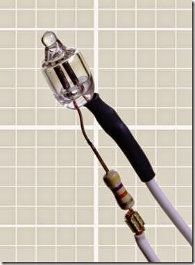
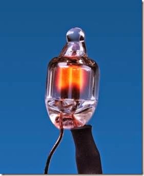
The photograph in Figure 19-2 shows a neon bulb with a series resistor preattached to one lead. Many bulbs are sold in this configuration, because a resistor must be used to limit current through the bulb. The bulb has no polarity and can be used on an AC or DC power supply. The same bulb is shown in its energized state in Figure 19-3.
Figure 19-2. A typical neon bulb with series resistor attached to one lead.
 How It Works
Construction
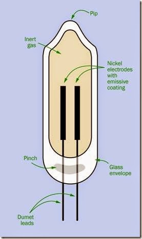
The parts of a neon bulb are illustrated in Figure 19-4. When the bulb is fabricated, it begins as a glass tube. The leads are made of dumet, consisting of a copper sheath around a nickel iron core. This has the same coefficient of expansion as glass, so that when the glass is heated and melted around the leads, it forms a seal that should be unaffected by subsequent temperature fluctuations. This area is known as the pinch in the tube.
Nickel electrodes are welded onto the leads be- fore the leads are inserted into the tube. The electrodes have an emissive coating that reduces the minimum operating voltage. The glass tube is filled with a combination of neon and argon gases, or pure neon for higher light output (which reduces the life of the component). The top end of the glass tube is heated until it melts, and is pinched off. This creates a distinctive protrusion known as the pip.
Figure 19-3. The same bulb from the previous photo- graph, energized with 115VAC.
Ionization
When a voltage is applied between the leads to the bulb, the gas becomes ionized, and electrons and ions are accelerated by the electric field. When they hit other atoms, these are ionized as well, maintaining the ionization level. Atoms are excited by collisions, moving their electrons to higher energy levels. When an electron returns from a higher level to a ground state, a photon is emitted.
This process begins at the starting voltage (also known as the striking voltage, the ignition volt- age, or the breakdown voltage) usually between 45V and 65V for standard types of bulb, or be- tween 70V and 95V for high-brightness types.
When the bulb is operating, it emits a soft radiance known as a glow discharge with a wave- length ranging from 600 to 700 nanometers.
Figure 19-4. The parts of a neon bulb. See text for details.
The ionization of the gas allows current to flow through it. This will continue even if the power supply is reduced by 10 to 20 volts to a level known as the maintaining voltage.
Negative Resistance
When the glow discharge persists below the starting voltage, this is a form of hysteresis, meaning that the neon bulb tends to “stick” in its on state. It remains on while its power supply de- creases to the maintaining voltage, but once it
switches off, it will “stick” in its off state until the power supply increases again above the maintaining voltage to the starting voltage. The concept of hysteresis is discussed in the entry on comparators. See Figure 6-2.
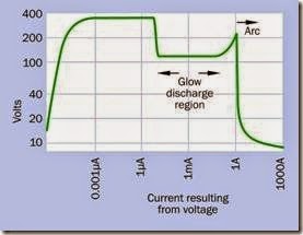
A neon bulb is said to have negative resistance. If the current is allowed to increase without restraint, the resistance eventually decreases while the current increases further. If this runaway behavior is not controlled, the bulb will destroy it- self.
This behavior is characteristic of gas-discharge tubes generally. A graph showing this appears in Figure 19-5. Note that both scales are logarithmic. Also note that the curve shows how current will be measured in response to voltage. If the voltage is reduced after it has increased, the transitional events shown by the graph will not recur in reverse order. This is especially true if arcing is allowed to begin, as it will almost certainly destroy the component.
Figure 19-5. A gas discharge tube, such as a neon bulb, is said to have a negative resistance, as current passing through it tends to increase uncontrollably after the gas is ionized and becomes conductive. (Derived from measurements made by David Knight, on a web page named after his radio ham call sign, G3YNH.)
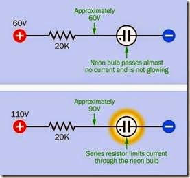
A neon bulb can be controlled very simply with a series resistor that maintains it in gas-discharge mode. To understand the operation of the resistor, consider the combination of the lamp and the resistor as a voltage divider, as shown in Figure 19-6. Before the lamp begins to pass cur- rent, it has an almost infinite resistance. There- fore, the voltage on both sides of the resistor will be approximately equal, the bulb passes almost no current, and it remains dark.
Figure 19-6. A series resistor is essential to limit the cur- rent through a neon bulb.
After the lamp begins to pass current, the requirement now is for the series resistor to reduce the voltage from the supply level (probably around 110V) to the maintaining level (probably around 90V). This means that the desired voltage drop is 20V, and if the manufacturer’s specification tells us that the lamp should pass 1mA (i.e.,
0.001 amps), R, the value of the series resistor, is given by Ohm’s Law:
R = 20 / 0.001
Thus, the value for R is 20K. In fact, the value of a resistor supplied with a neon bulb may range from 10K to 220K, depending on the characteristics of the bulb and the supply voltage that will be used.
Now if the bulb’s effective internal resistance falls radically, the resistor still limits the currrent. In a hypothetical worst-case scenario, if the bulb’s resistance drops all the way to zero, the resistor must now impose the full voltage drop of 110V, and the current, I, will be found by Ohm’s law:
I = 110 / 20,000 That is, about 5mA, or 0.005A.
Neon tubes used in signage require a more sophisticated voltage control circuit which is not included in this encyclopedia.
How to Use It
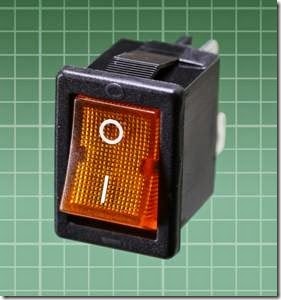
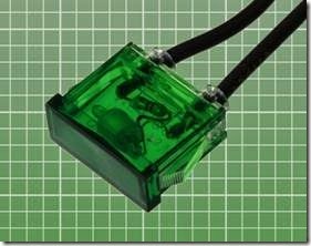
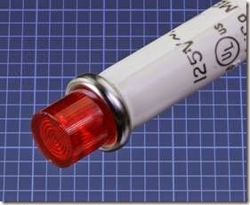
The use of a neon bulb for an indicator lamp is primarily limited to situations where domestic supply voltage (115VAC or 220VAC) is readily available. “Power on” lights are the obvious application, especially as neon indicators can accept AC. The switch shown in Figure 19-7 is illuminated by an internal neon bulb. The rectangular indicator in Figure 19-8 is designed to run on domestic supply voltage, and its internal bulb and resistor can be clearly seen through the green plastic. The assembly in Figure 19-9 is about 0.5” in diameter, which is the lower limit for neon indicators.
Figure 19-7. This power switch is illuminated by an internal neon bulb.
Figure 19-8. The neon bulb and its series resistor are visible inside this indicator.
Figure 19-9. A relatively small neon indicator lamp, de- signed for insertion in a hole 0.5” diameter.
Limited Light Output
Neon bulbs have a light output of around 0.06 lumens per milliamp of consumed power (standard brightness type) or 0.15 lumens per milliamp of consumed power (high brightness type).
Comparing this value with the intensity of LED indicators is difficult. Their light output is customarily measured in millicandelas (mcd), be- cause LED indicators almost always include a lens that focuses the light, and the candela is a measurement of luminous flux within an angle of dis-
persion. Moreover, because the intensity of neon indicators is not of great interest in most applications, datasheets usually do not supply an intensity value.
One way around the problem of comparisons is to use the standard of radiant luminous efficacy (LER), which is defined in the entry on incandescent lamps (see “Efficacy” on page 179). A standard-brightness neon bulb has an LER of about 50 lumens per emitted watt of luminous flux. A light-emitting diode may reach an LER of 100 lm/W. However, a neon bulb operates typi- cally around 1mA while an LED indicator may use 20mA. Therefore, a typical LED indicator may ap- pear to be 30 to 50 times brighter than a typical neon bulb.
Consequently, neon may be an inferior choice in a location where there is a high level of ambient light. Direct sunlight may render the glow of a neon indicator completely invisible.
Efficiency
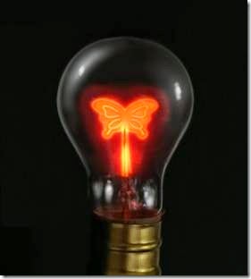
Because a neon bulb does not use a lot of power and generates negligible heat, it is a good choice where current consumption is a consideration (for example, if an indicator is likely to be on for long periods). The durability and low wattage of neon bulbs, and their convenient compatibility with domestic power-supply voltage, made them a favorite for night-lights and novelty lamps in the past. Figure 19-10 shows an antique bulb containing an ornamental electrode, while Figure 19-11 is a piece of folk art, approximately 1” in diameter, mounted on a plug-in plastic capsule containing a neon bulb.
Ruggedness
Neon bulbs are a good choice in difficult environments, as they are not affected by vibration, sudden mechanical shock, voltage transients, or frequent power cycling. Their operating temperature range is typically from -40 to +150 degrees Celsius, although temperatures above 100 degrees will reduce the life of the lamp.
Figure 19-10. In bygone decades, ornamental neon bulbs with specially shaped electrodes were popular.
Figure 19-11. Neon folk art survives in this hand-painted night-light sold in a Florida tourist shop.
Power-Supply Testing
When driven by DC current, only the negative electrode (the cathode) of a neon bulb will glow.
When AC current passes through the bulb, both terminals will glow.
If a bulb (with series resistor) is placed between the “hot” side of a domestic AC power supply and ground, the bulb will glow. If it is placed between the neutral side of the supply and ground, it will not glow.
These features enable a neon bulb to be used for simple power-supply testing.
Life Expectancy
The metal of the electrodes gradually vaporizes during everyday use of a neon bulb. This is known as sputtering and can be observed as the glass capsule becomes darkened by deposition of vaporized metal. The electrodes will have a more limited life in a lamp used with DC voltage, where sputtering affects only the cathode. Using AC, the electrodes take turns functioning as the cathode, and vaporization is distributed be- tween both of them.
Failure of a neon lamp can occur as sputtering erodes the electrodes to the point where the maintaining voltage will increase until it almost reaches the level of the power supply. At this point, the bulb will flicker erratically.
Failure can also be defined as a gradual reduction in brightness to 50% of rated light output, caused by accumulated deposition in the glass capsule. Because deposition occurs more heavily on the sides of the bulb, a longer apparent life is possible if the bulb is mounted so that it is viewed from the end.
Typically, neon bulbs are rated for 15,000 to 25,000 hours (two to three years of constant op- eration). However, the life can be greatly in- creased by a slight reduction in voltage, which may be achieved by substituting a series resistor with a slightly higher value.
The relationship between operating life and resistor value is shown below. If LA is the normal operating life, LB is the extended operating life,
RA is the normal resistor value, and RB is a higher resistor value:
LB = LA * ( RB / RA ) 3.3
For example, if a normal resistor value is 20K, and it is increased to 22K, the life of the lamp should increase by a factor of slightly more than 1.4.
Variants
A typical neon bulb terminates in leads, and a lamp assembly often has solder tabs, although it may have a base with a screw thread, flange, or bayonet pins for insertion into a compatible socket. A lamp assembly that does not use a base will either snap-fit into a hole of appropriate size and shape, or may be retained with a nut that engages with a plastic thread on the cylinder of the lamp.
Some neon bulbs or lamp assemblies terminate in pins for direct insertion into a printed circuit board.
Almost all neon bulbs operate either in the 100V to 120V range or in the 220V to 240V range.
Light intensity is expressed either as “standard” fied by their use of a numeral 5 that is a numeral 2 turned upside-down.
Nixie tubes typically require 170VDC. This creates a challenge for a power supply and switching, and can be a safety hazard.
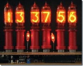
Figure 19-12 shows six Nixie-type tubes repurposed for use as a 24-hour digital clock.
Figure 19-12. A 24-hour clock using Nixie-type tubes. Source: Wikipedia, public domain.
What Can Go Wrong
or “extra-bright,” although datasheets usually do not define those terms.
Nixie Tubes
Nixie tubes, first marketed in 1955, were used to display numerals from 0 through 9 in the days before LEDs took over this capability. They are no longer being manufactured.
Each numeral was physically formed from metal and functioned as an electrode inside a tube filled with a neon-based gas mixture. The typo- graphical elegance of the digits and their aesthetically pleasing glow made Nixies enduringly popular. With a long lifespan, vintage tubes are still usable and can be purchased cheaply from sources such as eBay. Many originate in Russia, where Nixie-type displays were manufactured into the 1980s. The Russian tubes can be identiFalse Indication
Because a neon bulb requires so little power, it may be energized by induced voltages from else- where in a circuit, especially if inductive components such as transformers are used. To prevent this, a high-value resistor can be placed in parallel with the bulb, in addition to the series resistor that must always be used.
Failure in a Dark Environment Because a neon bulb requires a minimal amount of light to initiate its own photon emissions, it may take time to start glowing in a very dim environment, and may not light at all in total dark-ness. A few bulbs include a small amount of radioactive material that enables them to self-start in complete absence of ambient light.
Premature Failure with DC
The life expectancy quoted in datasheets for ne- on bulbs usually assumes that they are powered by AC. Because DC results in faster vaporization of the electrodes, the expected lifetime should be reduced by 50% if DC power will be used.
Premature Failure through Voltage Fluctuations
Because the deterioration of a neon bulb accelerates rapidly with current, a sustained voltage that passes slightly more current can radically reduce the expected lifespan.
Replacement
Replacement can be an issue with panel indicators, where disassembly of a device may be necessary to reach the bulb. Bear in mind, however, that an easily removable bulb becomes vulnerable to tampering.

