headphone:What It Does,How It Works,Audio Basics,Variants,Mechanical Design,Values,Intensity,Frequency Response,Distortion and Impedance.

headphone

The term headphone is used here to include almost any device that fits into or over the ear for the purpose of sound reproduction. (Hearing aids are not included.) Because headphones are used in pairs, the term is usually pluralized.

The term phones is fairly common as a colloquial diminution of headphones but is not used here.

An earphone used to be a single sound reproduction device designed for insertion into the ear, but has become rare. Pairs of earbuds are now common.

Because this encyclopedia assigns more emphasis to electronic components than to consumer products, this entry provides only a superficial overview of fully assembled headphones, and deals more with the drivers inside them, their principles of operation, and the general topic of sound reproduction.

What It Does

A headphone converts fluctuations of an electric signal into pressure waves that the human ear perceives as sound. It can be used for reproduction of music for entertainment purposes, or for speech in telecommunications, broadcasting, and audio recording.

Two symbols for headphones are shown in Figure 29-1. The symbol on the left shows a single headphone or earphone; when this symbol is flipped horizontally, it can represent a micro- phone. The pictographic symbol on the right has been used for many decades, but is still often found in schematics.

image

Figure 29-1. Schematic symbols for a single earphone or headphone (left) and a pair of headphones (right).

How It Works
Audio Basics

Sound is transmitted as pressure waves through a medium that is usually air but can be a gas, fluid, or solid. The speed of transmission will vary with the density and other attributes of the medium. Small hairs in the inner ears, known as cilia, vibrate in sympathy with pressure waves and transmit nerve impulses to the brain, which interprets the impulses as sound.

Three quantities describe the propagation of any type of wave, including a sound wave: its frequency (customarily represented with letter f ), its speed of propagation (represented with letter v, for velocity), and its wavelength from peak-to- peak (represented by the Greek letter lambda, which appears as this λ symbol).

The relationship is defined by a very simple equation:

v = λ * f

Velocity is usually measured in meters per second, wavelength in meters, and frequency in Hertz, abbreviated Hz. One cycle per second is 1Hz. The H is always capitalized, as it refers to the name of Heinrich Rudolf Hertz, the first scientist to prove the existence of electromagnetic waves. One thousand Hertz can be written as 1 kilo- Hertz, almost always abbreviated as 1kHz (note that the k is lowercase).

The human ear is often described as being able to detect sounds between 20Hz and 20kHz, al- though the ability to hear sounds above 15kHz is relatively unusual and diminishes naturally with age. Sensitivity to all frequencies can be impaired by long-term exposure to loud noise.

Naturally occurring sounds can be converted to fluctuations in voltage by a microphone, which will be found listed as a sensor in Volume 3 of this encyclopedia. Artificial sounds can be generated as voltage fluctuations by oscillators and other electronic circuits. In either case, the output fluctuations can range between an upper limit set by a positive supply voltage and a lower limit established by electrical ground (which is assumed to be 0 volts). Alternatively, the fluctuations can range between the positive supply voltage and an equal and opposite negative supply voltage, with 0V lying midway between the two. This op- tion can be less convenient electrically but is a more direct representation of sound, because sound waves fluctuate above and below ambient air pressure, which can be considered analogous to a ground state.

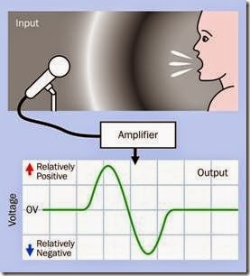
The concept of positive and negative sound waves is illustrated in Figure 29-2 (originally published in the book Make: More Electronics).

clip_image008

Figure 29-2. The use of positive and negative voltages to represent a wave of high sound pressure followed by a trough of lower pressure.

The topic of sound amplification is explored in detail in the entry on op-amps in Chapter 7.

A headphone inverts the function of a micro- phone by converting electricity back into air- pressure waves. This is done electromagnetically (moving a diaphragm in response to an electro- magnet) or electrostatically (moving a membrane in response to electrostatic force between two charged electrodes).

Variants
Moving Coil

The most enduringly popular type of headphone uses a coil attached to a diaphragm. This is known as a moving-coil headphone, as the coil moves with the diaphragm. It can also be referred to as having a dynamic driver or dynamic transducer, “dynamic” referring to the movement of the coil.

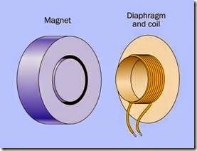
The moving-coil concept is illustrated in Figure 29-3. The coil slides into a deep, narrow, circular slot in a magnet that is attached to the plastic frame of the headphone. The diaphragm is supported at its edges by a flexible rim. Variations in current passing through the coil create a fluctuating magnetic field that interacts with the field of the fixed magnet, causing the diaphragm to move in and out. A very similar configuration is used in many loudspeakers. Detail modifications may be made to increase efficiency, reduce production costs, or enhance sound quality, but the principle remains the same.

clip_image010

Figure 29-3. The basic elements of a moving-coil head- phone.

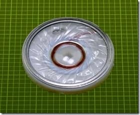
The internal element of a headphone is shown in Figure 29-4. A plastic diaphragm is visible, measuring slightly less than 2” in diameter. The mag- net and coil are concealed underneath.

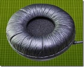
The element in the previous figure is normally enclosed in an assembly such as the one in Figure 29-5, which incorporates a soft padded rim to rest upon the ear.

In an effort to achieve a more balanced frequency response, some designs use two moving-coil drivers in each headphone, optimized for low frequencies and high frequencies, respectively.

Earbuds, described after the next section, often use a miniaturized version of the moving-coil design.

clip_image012

Figure 29-4. The sound reproducing element removed from a headphone.

clip_image014

Figure 29-5. The sound reproducing element from the previous figure is normally packaged inside this enclosure.

Other Types

Electrostatic headphones use a thin, flat diaphragm suspended between two grids that function as electrodes. A fluctuating potential between the grids, coupled with a reverse-phase voltage on the diaphragm, will vibrate the diaphragm, generating pressure waves. A relatively high voltage is necessary to achieve this, any- where from 100V to 1,000V, supplied through a conversion unit between the headphones and an amplifier. Electrostatic headphones are known for low distortion and an excellent high frequency response, at some extra cost.

Electret headphones work on a similar principle, except that the membrane is permanently charged, and a high voltage is not required. Electret headphones tend to be small, inexpensive, and not of high sound quality.

A balanced armature design, often referred to by the acronym BA, uses a pivoting magnet that is claimed to increase efficiency while reducing stress on a diaphragm. BA drivers can be extremely compact, contained within a sealed met- al enclosure measuring less than 10mm x 10mm x 5mm. They are commonly used in conjunction with in-ear earphones, described in the next section.

Mechanical Design

Circumaural headphones use large soft pads to encircle the ear and block external noise. Their size tends to make them heavy, requiring a well- designed headband to provide comfortable sup- port. Supra-aural headphones are smaller and lighter, resting on the ears instead of enclosing them. They cannot exclude ambient noise, and may have inferior bass response compared with the circumaural type.

Open-back headphones, also known as acoustically transparent, are favored by some audiophiles because their vented outer surfaces are thought to create a more natural sound, similar to that of a speaker. The open backs naturally allow ambient noise to intrude, but also allow the sound generated by the headphones to be heard by others in a room. Closed-back headphones contain their sound and provide more insulation against ambient noise.

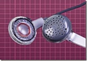
Earbuds rest just within the outer folds of the ear, facing inward like a pair of tiny speakers. They are easily dislodged and provide very little insulation against ambient noise. Their use became common after the introduction of Apple’s iPod. A pair of earbuds, one of them with its plastic cover removed, is shown in Figure 29-6.

clip_image016

Figure 29-6. A pair of earbuds, one with its cover re- moved to show the sound reproducing element, which closely resembles the diaphragm in a full-sized head- phone.

In-ear headphones are designed for insertion into the ear canal, often using a soft sheath that con- forms with the ear like an earplug. This sheath is disposable for hygienic reasons, and because it may lose some of its plasticity with use. It excludes most ambient noise, and by minimizing the air gap between the driver of the headphone and the ear drum enables a high quality of sound reproduction.

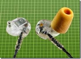
In-ear headphones are also known as in-ear monitors, IEMs, ear canal headphones, earphones, and canalphones. A pair of in-ear headphones is shown in Figure 29-7, one of them with its foam sheath removed. The rectangular silver-colored object in the headphone on the left contains a transducer to create sound pressure.

A headset consists of one or two headphones plus a flexible microphone that extends to the promiximity of the mouth of the user.

Noise-cancelling headphones, popularized by Bose, monitor external noise with a built-in microphone and generate sound of opposite phase, to provide some cancellation. They are particularly effective on jet aircraft, where back- ground noise tends to be consistent.

clip_image018

Figure 29-7. A pair of in-ear headphones, supplied with disposable foam plugs that conform flexibly with the ear canal. The headphone on the left is shown with its plug re- moved.

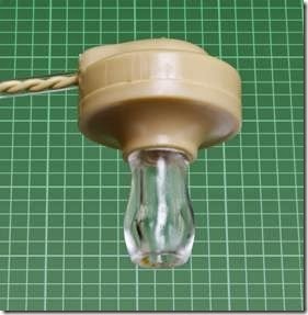
Although an earphone is almost obsolete, it is still obtainable from specialty suppliers. It has a high impedance, making it suitable for use with a crystal-set radio. An earphone is pictured in Figure 29-8.

clip_image020

Figure 29-8. A vintage earphone of the type suitable for use with a crystal-set radio.

Values
Intensity

Sound pressure is measured in decibels. For a complete explanation and discussion of weigh- ted and unweighted decibel scales, see “Sound Pressure” on page 251 in the transducer entry.

Frequency Response

A plot of sound pressure as a function of frequency shows the frequency response of a head- phone. Measuring the sound pressure meaning- fully is a challenge, because the ear canal will add coloration to the sound and can amplify some frequencies while masking others. Ideally, measurement should be done at the ear drum, but this is not feasible. Consequently, high-end head- phones are evaluated by making sound measurements inside simulated ear canals in a dummy human head.

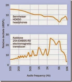
A comparison between a high-quality $500 audio product and a transducer that is sold as a component for less than $1 illustrates the difference in frequency response; see Figure 29-9. The Sennheiser headphones have a smooth response that rises toward the low end, compensating for the lack of bass response that tends to be a problem in headphones, and the relative in- sensitivity of the human ear to low frequencies. The fluctuations at the high end are within about 5dB.

By comparison, the Kobitone emphasizes the range between 3kHz and 4kHz because its primary task is to be heard, and these are the frequencies where human hearing is most sensitive. Its low-frequency response trails off (although is still much better than that of a piezoelectric transducer, where the low response typically diminishes by 40dB to 50dB). The low-frequency output of the Kobitone is actually impressive bearing in mind that the component is only 9mm in diameter. It draws 60mA at 5VAC.

clip_image022

Figure 29-9. Comparison between frequency responses of a $1 electromagnetic transducer intended as an audio alert and a $500 pair of headphones intended for sound reproduction. The upper graph is derived from a review online at headroom.com; the lower graph is from the manufacturer’s datasheet.

Some manufacturers of audio reproduction equipment prefer not to supply frequency response curves. Instead they may claim, for ex- ample, that the frequency response of a product ranges from 100Hz to 20kHz. This claim means very little unless it is accompanied by a range of sound pressure levels. If the frequency response is consistent within a range of, say, plus-or-minus 5dB, this may be acceptable. If the range is plus- or-minus 20dB, it is not acceptable. The ability to reproduce a high note or a low note is not useful if the sound is too faint to hear.

Distortion

The total harmonic distortion (THD) of any audio equipment measures its tendency to add spuri- ous harmonics of a single frequency. If head- phones are required to reproduce a pure 1kHz sinewave, they will also tend to create an addi- tional 3kHz tone that is an artifact. This can be caused by the mechanical behavior of a vibrating diaphragm. The human ear recognizes distortion as a fuzzy or rasping sound. A square wave the- oretically contains all the harmonics that are odd multiples of its fundamental frequency, and sounds extremely distorted.

THD should be less than 1% in good-quality au- dio devices.

Impedance

The electrical impedance of headphones is relevant in that it should match the output specifi- cation of the amplifier that drives them.

What Can Go Wrong
Overdriving

Headphones can be damaged by overdriving them. Because a low frequency requires larger excursions of a diaphragm to transmit the same energy as a high frequency, headphones are especially vulnerable to being damaged by bass at high volume.

Hearing Damage

Human hearing can be damaged by prolonged listening to headphones at a high volume. Some controversy remains regarding an acceptable limit for sound pressure.

Mismatched Impedance

If the impedance of headphones does not match the output of the amplifier driving them, distortion or a skewed frequency response can result. This is known as mismatching.

Incorrect Wiring

In most consumer products, a pair of head- phones will share a common ground. While the connections in a typical three-layer jack plug have been standardized, hand-wired repairs or extensions should be tested carefully. Incorrect wiring will cause unpredictable results.

Leave a comment

Your email address will not be published. Required fields are marked *

headphone:What It Does,How It Works,Audio Basics,Variants,Mechanical Design,Values,Intensity,Frequency Response,Distortion and Impedance.

headphone

The term headphone is used here to include almost any device that fits into or over the ear for the purpose of sound reproduction. (Hearing aids are not included.) Because headphones are used in pairs, the term is usually pluralized.

The term phones is fairly common as a colloquial diminution of headphones but is not used here.

An earphone used to be a single sound reproduction device designed for insertion into the ear, but has become rare. Pairs of earbuds are now common.

Because this encyclopedia assigns more emphasis to electronic components than to consumer products, this entry provides only a superficial overview of fully assembled headphones, and deals more with the drivers inside them, their principles of operation, and the general topic of sound reproduction.

What It Does

A headphone converts fluctuations of an electric signal into pressure waves that the human ear perceives as sound. It can be used for reproduction of music for entertainment purposes, or for speech in telecommunications, broadcasting, and audio recording.

Two symbols for headphones are shown in Figure 29-1. The symbol on the left shows a single headphone or earphone; when this symbol is flipped horizontally, it can represent a micro- phone. The pictographic symbol on the right has been used for many decades, but is still often found in schematics.

image

Figure 29-1. Schematic symbols for a single earphone or headphone (left) and a pair of headphones (right).

How It Works
Audio Basics

Sound is transmitted as pressure waves through a medium that is usually air but can be a gas, fluid, or solid. The speed of transmission will vary with the density and other attributes of the medium. Small hairs in the inner ears, known as cilia, vibrate in sympathy with pressure waves and transmit nerve impulses to the brain, which interprets the impulses as sound.

Three quantities describe the propagation of any type of wave, including a sound wave: its frequency (customarily represented with letter f ), its speed of propagation (represented with letter v, for velocity), and its wavelength from peak-to- peak (represented by the Greek letter lambda, which appears as this λ symbol).

The relationship is defined by a very simple equation:

v = λ * f

Velocity is usually measured in meters per second, wavelength in meters, and frequency in Hertz, abbreviated Hz. One cycle per second is 1Hz. The H is always capitalized, as it refers to the name of Heinrich Rudolf Hertz, the first scientist to prove the existence of electromagnetic waves. One thousand Hertz can be written as 1 kilo- Hertz, almost always abbreviated as 1kHz (note that the k is lowercase).

The human ear is often described as being able to detect sounds between 20Hz and 20kHz, al- though the ability to hear sounds above 15kHz is relatively unusual and diminishes naturally with age. Sensitivity to all frequencies can be impaired by long-term exposure to loud noise.

Naturally occurring sounds can be converted to fluctuations in voltage by a microphone, which will be found listed as a sensor in Volume 3 of this encyclopedia. Artificial sounds can be generated as voltage fluctuations by oscillators and other electronic circuits. In either case, the output fluctuations can range between an upper limit set by a positive supply voltage and a lower limit established by electrical ground (which is assumed to be 0 volts). Alternatively, the fluctuations can range between the positive supply voltage and an equal and opposite negative supply voltage, with 0V lying midway between the two. This op- tion can be less convenient electrically but is a more direct representation of sound, because sound waves fluctuate above and below ambient air pressure, which can be considered analogous to a ground state.

The concept of positive and negative sound waves is illustrated in Figure 29-2 (originally published in the book Make: More Electronics).

clip_image008

Figure 29-2. The use of positive and negative voltages to represent a wave of high sound pressure followed by a trough of lower pressure.

The topic of sound amplification is explored in detail in the entry on op-amps in Chapter 7.

A headphone inverts the function of a micro- phone by converting electricity back into air- pressure waves. This is done electromagnetically (moving a diaphragm in response to an electro- magnet) or electrostatically (moving a membrane in response to electrostatic force between two charged electrodes).

Variants
Moving Coil

The most enduringly popular type of headphone uses a coil attached to a diaphragm. This is known as a moving-coil headphone, as the coil moves with the diaphragm. It can also be referred to as having a dynamic driver or dynamic transducer, “dynamic” referring to the movement of the coil.

The moving-coil concept is illustrated in Figure 29-3. The coil slides into a deep, narrow, circular slot in a magnet that is attached to the plastic frame of the headphone. The diaphragm is supported at its edges by a flexible rim. Variations in current passing through the coil create a fluctuating magnetic field that interacts with the field of the fixed magnet, causing the diaphragm to move in and out. A very similar configuration is used in many loudspeakers. Detail modifications may be made to increase efficiency, reduce production costs, or enhance sound quality, but the principle remains the same.

clip_image010

Figure 29-3. The basic elements of a moving-coil head- phone.

The internal element of a headphone is shown in Figure 29-4. A plastic diaphragm is visible, measuring slightly less than 2” in diameter. The mag- net and coil are concealed underneath.

The element in the previous figure is normally enclosed in an assembly such as the one in Figure 29-5, which incorporates a soft padded rim to rest upon the ear.

In an effort to achieve a more balanced frequency response, some designs use two moving-coil drivers in each headphone, optimized for low frequencies and high frequencies, respectively.

Earbuds, described after the next section, often use a miniaturized version of the moving-coil design.

clip_image012

Figure 29-4. The sound reproducing element removed from a headphone.

clip_image014

Figure 29-5. The sound reproducing element from the previous figure is normally packaged inside this enclosure.

Other Types

Electrostatic headphones use a thin, flat diaphragm suspended between two grids that function as electrodes. A fluctuating potential between the grids, coupled with a reverse-phase voltage on the diaphragm, will vibrate the diaphragm, generating pressure waves. A relatively high voltage is necessary to achieve this, any- where from 100V to 1,000V, supplied through a conversion unit between the headphones and an amplifier. Electrostatic headphones are known for low distortion and an excellent high frequency response, at some extra cost.

Electret headphones work on a similar principle, except that the membrane is permanently charged, and a high voltage is not required. Electret headphones tend to be small, inexpensive, and not of high sound quality.

A balanced armature design, often referred to by the acronym BA, uses a pivoting magnet that is claimed to increase efficiency while reducing stress on a diaphragm. BA drivers can be extremely compact, contained within a sealed met- al enclosure measuring less than 10mm x 10mm x 5mm. They are commonly used in conjunction with in-ear earphones, described in the next section.

Mechanical Design

Circumaural headphones use large soft pads to encircle the ear and block external noise. Their size tends to make them heavy, requiring a well- designed headband to provide comfortable sup- port. Supra-aural headphones are smaller and lighter, resting on the ears instead of enclosing them. They cannot exclude ambient noise, and may have inferior bass response compared with the circumaural type.

Open-back headphones, also known as acoustically transparent, are favored by some audiophiles because their vented outer surfaces are thought to create a more natural sound, similar to that of a speaker. The open backs naturally allow ambient noise to intrude, but also allow the sound generated by the headphones to be heard by others in a room. Closed-back headphones contain their sound and provide more insulation against ambient noise.

Earbuds rest just within the outer folds of the ear, facing inward like a pair of tiny speakers. They are easily dislodged and provide very little insulation against ambient noise. Their use became common after the introduction of Apple’s iPod. A pair of earbuds, one of them with its plastic cover removed, is shown in Figure 29-6.

clip_image016

Figure 29-6. A pair of earbuds, one with its cover re- moved to show the sound reproducing element, which closely resembles the diaphragm in a full-sized head- phone.

In-ear headphones are designed for insertion into the ear canal, often using a soft sheath that con- forms with the ear like an earplug. This sheath is disposable for hygienic reasons, and because it may lose some of its plasticity with use. It excludes most ambient noise, and by minimizing the air gap between the driver of the headphone and the ear drum enables a high quality of sound reproduction.

In-ear headphones are also known as in-ear monitors, IEMs, ear canal headphones, earphones, and canalphones. A pair of in-ear headphones is shown in Figure 29-7, one of them with its foam sheath removed. The rectangular silver-colored object in the headphone on the left contains a transducer to create sound pressure.

A headset consists of one or two headphones plus a flexible microphone that extends to the promiximity of the mouth of the user.

Noise-cancelling headphones, popularized by Bose, monitor external noise with a built-in microphone and generate sound of opposite phase, to provide some cancellation. They are particularly effective on jet aircraft, where back- ground noise tends to be consistent.

clip_image018

Figure 29-7. A pair of in-ear headphones, supplied with disposable foam plugs that conform flexibly with the ear canal. The headphone on the left is shown with its plug re- moved.

Although an earphone is almost obsolete, it is still obtainable from specialty suppliers. It has a high impedance, making it suitable for use with a crystal-set radio. An earphone is pictured in Figure 29-8.

clip_image020

Figure 29-8. A vintage earphone of the type suitable for use with a crystal-set radio.

Values
Intensity

Sound pressure is measured in decibels. For a complete explanation and discussion of weigh- ted and unweighted decibel scales, see “Sound Pressure” on page 251 in the transducer entry.

Frequency Response

A plot of sound pressure as a function of frequency shows the frequency response of a head- phone. Measuring the sound pressure meaning- fully is a challenge, because the ear canal will add coloration to the sound and can amplify some frequencies while masking others. Ideally, measurement should be done at the ear drum, but this is not feasible. Consequently, high-end head- phones are evaluated by making sound measurements inside simulated ear canals in a dummy human head.

A comparison between a high-quality $500 audio product and a transducer that is sold as a component for less than $1 illustrates the difference in frequency response; see Figure 29-9. The Sennheiser headphones have a smooth response that rises toward the low end, compensating for the lack of bass response that tends to be a problem in headphones, and the relative in- sensitivity of the human ear to low frequencies. The fluctuations at the high end are within about 5dB.

By comparison, the Kobitone emphasizes the range between 3kHz and 4kHz because its primary task is to be heard, and these are the frequencies where human hearing is most sensitive. Its low-frequency response trails off (although is still much better than that of a piezoelectric transducer, where the low response typically diminishes by 40dB to 50dB). The low-frequency output of the Kobitone is actually impressive bearing in mind that the component is only 9mm in diameter. It draws 60mA at 5VAC.

clip_image022

Figure 29-9. Comparison between frequency responses of a $1 electromagnetic transducer intended as an audio alert and a $500 pair of headphones intended for sound reproduction. The upper graph is derived from a review online at headroom.com; the lower graph is from the manufacturer’s datasheet.

Some manufacturers of audio reproduction equipment prefer not to supply frequency response curves. Instead they may claim, for ex- ample, that the frequency response of a product ranges from 100Hz to 20kHz. This claim means very little unless it is accompanied by a range of sound pressure levels. If the frequency response is consistent within a range of, say, plus-or-minus 5dB, this may be acceptable. If the range is plus- or-minus 20dB, it is not acceptable. The ability to reproduce a high note or a low note is not useful if the sound is too faint to hear.

Distortion

The total harmonic distortion (THD) of any audio equipment measures its tendency to add spuri- ous harmonics of a single frequency. If head- phones are required to reproduce a pure 1kHz sinewave, they will also tend to create an addi- tional 3kHz tone that is an artifact. This can be caused by the mechanical behavior of a vibrating diaphragm. The human ear recognizes distortion as a fuzzy or rasping sound. A square wave the- oretically contains all the harmonics that are odd multiples of its fundamental frequency, and sounds extremely distorted.

THD should be less than 1% in good-quality au- dio devices.

Impedance

The electrical impedance of headphones is relevant in that it should match the output specifi- cation of the amplifier that drives them.

What Can Go Wrong
Overdriving

Headphones can be damaged by overdriving them. Because a low frequency requires larger excursions of a diaphragm to transmit the same energy as a high frequency, headphones are especially vulnerable to being damaged by bass at high volume.

Hearing Damage

Human hearing can be damaged by prolonged listening to headphones at a high volume. Some controversy remains regarding an acceptable limit for sound pressure.

Mismatched Impedance

If the impedance of headphones does not match the output of the amplifier driving them, distortion or a skewed frequency response can result. This is known as mismatching.

Incorrect Wiring

In most consumer products, a pair of head- phones will share a common ground. While the connections in a typical three-layer jack plug have been standardized, hand-wired repairs or extensions should be tested carefully. Incorrect wiring will cause unpredictable results.
Leave a comment

Your email address will not be published. Required fields are marked *