luorescent light
This entry deals primarily with fluorescent tubes (infrequently but sometimes described as fluorescent lamps), and compact fluorescent lamps (CFLs) that are marketed as a substitute for incandescent lamps. Cold-cathode fluorescent lamps (CCFLs) are also mentioned.
Vacuum fluorescent devices have a separate entry in this encyclopedia. A fluorescent tube or CFL does not contain a vacuum.
Although the diode(s) in a white LED area lighting unit are coated with a layer of fluorescent phosphors, they are not categorized here as fluorescent lights, and have their own entry.
A neon bulb resembles a fluorescent light in that it is a gas-discharge device, but the interior of its glass envelope is usually not coated with fluorescent phosphors, and there- fore it has its own entry.
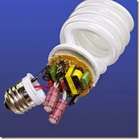
Fluorescent tubes or compact fluorescent lamps (CFLs) are primarily used for area lighting. A partially disassembled CFL appears in Figure 20-1, showing the control electronics that are normally hidden inside the base.
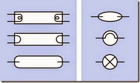
There is no standardized schematic symbol to represent a fluorescent light. Figure 20-2 shows three commonly used symbols for a fluorescent tube on the left, and three symbols for a CFL on the right. Note that two of the symbols for a CFL are the same as those for an incandescent lamp, shown in Figure 18-1.
How It Works
Luminescence is the emission of light as a result of a process that does not require heat. (The op- posite phenomenon is incandescence, in which heating causes an object to emit light; see Chapter 18 for a description of incandescent lamps.)
Fluorescence is a form of luminescence. It occurs when electrons in a material are energized and then make a transition back to ground level, at which point they radiate their energy as visible light. The incoming energy can consist of other light at a higher frequency. Some creatures, including species of arachnids and fish, will fluoresce when they are lit with ultraviolet light.
Figure 20-1. A compact fluorescent lamp with its base cut away to reveal the control electronics.
Figure 20-2. Schematic symbols to represent fluorescent tubes and bulbs are not standardized. See text for details.
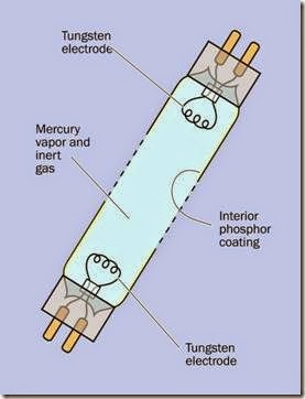
A fluorescent tube or lamp contains a very small amount of mercury vapor that can be stimulated to emit ultraviolet light. This encounters a thin layer of phosphors coating the inner surface of the glass enclosure. The light causes the phosphors to fluoresce, emitting a diffuse radiance in the visible spectrum.
The tube or lamp also contains one or more inert gases such as argon, xenon, neon, or krypton at about 0.3% of normal atmospheric pressure. Two electrodes inside the glass enclosure are made primarily from tungsten, which can be preheated to initiate ionization of the gas. Confusingly, both electrodes are often referred to as cathodes.
The function of the gas is not to emit light, but to conduct electric current, so that free electrons may encounter mercury atoms, raising their electrons briefly to a higher energy level. When one of these electrons reverts from its unstable energized state to its previous energy level, it emits a photon at an ultraviolet wavelength.
Figure 20-3 provides a diagram showing the interior of a fluorescent tube.
Figure 20-3. The basic parts of a fluorescent tube.
Ballast and Starter
Heating the tungsten electrodes is necessary but not sufficient to trigger ionization. A high- voltage pulse is also needed when the light is switched on. In a typical 48” tube, the pulse may range from 200V to 300V.
After current flow has been established, the gas, which is now a plasma, enters a phase of negative resistance. Current passing through it will tend to increase even if the voltage decreases. This process must be controlled to prevent the formation of an arc, which will destroy the electro- des. (A similar process occurs in any gas dis- charge tube, such as a neon bulb, and is de- scribed in a graph in Figure 19-5.)
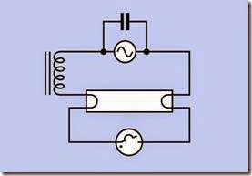
To heat the electrodes, ionize the gas, and then control the current, the fixture for a fluorescent tube contains components that are separate from the tube. In their simplest, traditional form, these components consist of a starter and a ballast. The starter is a neon bulb that contains a bimetallic strip serving as a normally closed switch. It allows current to flow through the electrodes in series, to heat them. The basic circuit is shown in Figure 20-4.
Figure 20-4. The traditional circuit to trigger ionization of the gas in a fluorescent tube uses a starter (shown at the bottom as a neon tube containing a bimetallic strip, which serves as a switch) and ballast (an inductive load, shown at left).
The starting process may not be immediately successful, in which case the starter may repeat several times in succession, causing the tube to flicker before its discharge becomes stable. In a cold environment, the tube will have more difficulty starting.
After the tube becomes conductive, current be- tween the electrodes bypasses the starter. At this point, the ballast limits the current to prevent an arc from forming. The simplest form of ballast is a coil that functions as an inductor.
In a more modern system, an electronic ballast replaces the starter-ballast combination. It not only applies the initial surge of high current but also raises the 50Hz or 60Hz frequency of the power supply to 10KHz or more. This increases the efficiency of the tube and eliminates any visible flickering of the light.
All compact fluorescent bulbs (CFLs) contain electronic ballasts. The small components visible in Figure 20-1 are the ballast.
Flicker
When a fluorescent tube uses a conventional ballast and is illuminated with 50Hz or 60Hz AC, the glow discharge stops each time the current flow passes through the zero point in its cycle. In fact, the ionized gas in the tube cannot conduct until it is close to the maximum voltage, and stops conducting when the voltage rolls off. Consequently, the voltage across the tube fluctuates in an approximate square wave, and the light output begins and ends very abruptly. Although this occurs 100 times per second on a 50Hz sup- ply and 120 times per second on a 60Hz supply, some people complain that the flicker is notice- able and can induce headaches.
The rapid on-off discharge is hazardous when it illuminates rotating parts in machinery, as a stroboscopic effect can make the parts seem to be stationary. To mitigate this effect, adjacent tubes in a fixture are powered by separate supplies that are out of phase. This is done either by using a three-phase power supply or by adding an LC circuit to the supply for one of the tubes.
Variants
The traditional type of ballast is also known as a rapid-start ballast. By preheating the electrodes, it reduces damage to them that otherwise tends to occur during the starting process. A tube de- signed for use with a rapid-start ballast has two contacts at each end, and is referred to as a bi- pin tube.
An electronic ballast is also known as an instant- start ballast. It does not preheat the electrodes, and a tube designed to work with it has only one pin at each end.
CCFLs
A cold cathode fluorescent lamp (CCFL) may resemble a miniature fluorescent tube, typically measuring 2mm to 5mm in diameter. The tube may be straight or bent into a variety of shapes. It works on the same principle as a full-size fluorescent tube, containing mercury vapor and one or more inert gases, with an interior coating of phosphors to enable fluorescence. CCFLs are available in many colors and many shades of white.
As its name implies, the electrodes in a CCFL are not heated to establish ionization. Instead, a very high voltage (1,000VAC or more) is applied, drop- ping to 500VAC to 600VAC after the flow of cur- rent has been established. Because CCFLs have been often used to backlight laptop computer screens, inverter circuits are commonly available that create a high-frequency output at a high voltage from an input that can range from 3VDC to 20VDC. The inverter also includes provision to dim the CCFL by using pulse-width modulation.
Some CCFLs are designed for illumination of small spaces—for example, the interior of a dis- play case. A few CCFLs look exactly like CFLs and can be used in light fixtures. Some may be compatible with the type of dimmer designed for in- candescent lamps.
A CCFL usually has a limited light output com- pared with that of a conventional fluorescent tube, but has the advantage of working better at low temperatures. Some are designed for signage and exterior lighting in cold-weather locations.
They have a relatively long lifetime of up to 60,000 hours. A hot-cathode fluorescent lamp may fail between 3,000 and 15,000 hours.
Any tube or bulb that uses unheated electrodes to ionize a gas is technically a cold-cathode de- vice, but will not be identified as a CCFL unless it also has an inner layer of phosphors to achieve fluorescence.
It is important to match a tube with the type of ballast installed in a fixture. This is not an issue with CFLs, as they have the appropriate ballast built in.
Sizes
Straight bi-pin tubes are sold in the United States in the following standard sizes:
• T5: 5/8” diameter. A more modern tube, but still with tungsten electrodes that serve to heat it.
• T8: 1” diameter. Very often 24” or 48” in length, consuming 18W or 36W respectively.
• T12: 1-1/2” diameter.
• T17: 2-1/8” diameter.
CFLs are sold in a very wide variety of configurations.
Comparisons
Fluorescent lights have significant advantages and disadvantages. On the plus side:
• After the fixture containing the ballast has been paid for, a tube is relatively cheap. A CFL or an LED light does not have this advantage, as the electronics are built in and will be dis- carded when the light fails.
• Fluorescent lights have a longer life than in- candescent bulbs.
• Fluorescent lights are available in a wide range of shades of white.
• Fluorescent tubes create a diffuse radiance that is ideal for general lighting using ceiling- mounted fixtures. They do not cast harsh shadows.
On the minus side:
• Fluorescents were traditionally more energy-efficient than any other light source, but LED area lighting is now more efficient in some designs. LEDs are expected to be- come more efficient in the future.
• A fluorescent tube with a traditional type of ballast may cause complaints of flickering. By comparison, an LED light uses DC, and an in- candescent bulb retains sufficient heat be- tween power cycles so that it does not ap- pear to flicker.
• Fluorescent flicker creates problems when shooting video.
• The fluorescent emission spectrum has sharp peaks that give the lighting an un- natural look.
• In applications that require a defined beam of light, a fluorescent source cannot be used.
• Conventional ballasts can create radio inter- ference, especially in the AM band.
• Because fluorescent tubes and bulbs contain mercury, they require proper disposal, which can incur fees.
• Even an instant-on fluorescent light tends to hesitate briefly when it is switched on.
• The lifespan of a fluorescent light is greatly reduced if it is cycled on and off frequently. An incandescent bulb is less severely affec- ted by cycling, and an LED light is not affec- ted at all.
• Fluorescent lights have difficulty starting at low temperatures.
Values
Brightness
The intensity of a fluorescent light is measured in lumens per watt. Because invisible wavelengths are of little interest when assessing brightness, luminous flux is used to describe apparent bright-
ness in the visible spectrum. The unit for luminous flux is the lumen. Additional information about light measurement is included in the entry describing incandescent lamps (see “Power” on page 177).
Spectrum
The spectrum of photons emitted from mercury vapor in a fluorescent light has wavelengths that peak at 253.7 nanometers and 185 nanometers. (A nanometer, customarily abbreviated as nm, is one-billionth of a meter.) These wavelengths are invisible, being in the ultraviolet range, but when the light is transposed into the visible spectrum by the layer of phosphors, “spikes” in the range of wavelengths are still present. For a comparison of output curves for incandescent, fluorescent, and LED lights, see the graph in Figure 18-4.
Various formulations for the phosphors in a tube or CFL attempt to modify the character of the light to suit the human eye, but none of them looks as “natural” as the radiance from an incandescent bulb, probably because the characteristics of incandescent light are very similar to those of sunlight.
What Can Go Wrong
Unreliable Starting
At a low temperature, the mercury inside a fluorescent tube may be slow to vaporize. At very low temperatures, vaporization may not be possible at all. Until the mercury vaporizes, fluorescence will not occur.
Terminal Flicker
As a tube ages, it may start to conduct current only in one direction, causing it to flicker visibly. As it ages more, the gas discharge becomes even less reliable, and the flicker becomes erratic. Eventually, the gas discharge fails completely. In this state, a tube may show only a dim light at each end, in proximity to the tungsten electrodes.
Cannot Dim
Neither the older style of “conventional” ballast nor a modern electronic ballast will respond appropriately to a dimmer of the type designed for incandescent bulbs. This may be an important factor when an incandescent bulb is swapped out for a CFL.
Burned Out Electrodes
Like the tungsten filament in an incandescent lamp, the tungsten electrodes in a fluorescent tube suffer progressive erosion. This is evident when a black tungsten deposit forms on the in- side of the tube at one or both ends.
Ultraviolet Hazard
Some critics of CFLs maintain that the complex shape of a coiled or zigzag tube tends to permit small imperfections in the internal phosphor coating, potentially allowing ultraviolet light to escape. If this occurs, and if a CFL is used in a desk fixture in close proximity to the user, ultraviolet light could elevate the risk of skin cancer.


