electroluminescence
The field of electroluminescent devices is sometimes referred to as EL. The same acronym can also be applied as an adjective to an individual electroluminescent device, as in, for example, “an EL panel.”
An organic light-emitting diode, more commonly known by its acronym OLED, is included in this entry because it is technically an electroluminescent device and its design concept is similar to that of an electroluminescent panel. Generic LEDs are also technically electroluminescent, but are not commonly described as such, and have their own entries in this encyclopedia under the subject categories LED indicator, LED area lighting, and LED display.
What It Does
An electroluminescent device configured as a panel, ribbon, or rope-light contains phosphors that emit light in response to a flow of electricity.
Panels can be used as backlights for LCD displays or, more often, as always-on low-power devices such as exit signs and night lights. Ribbons and rope lights (the latter being also known, more accurately, as light wires) are used mainly as recreational novelties. They can be battery powered through a suitable voltage converter. A battery- powered rope light can be wearable.
Thin-film OLED electroluminescent panels are used in small video screens in handheld devices. At the time of writing, OLED TV screens measuring 50” or more have been demonstrated, but are not yet economic for mass production.
No specific schematic symbol exists to represent any electroluminescent device or component.
How It Works
Luminescence is the emission of light as a result of a process that does not require heat. (The opposite phenomenon is incandescence, in which heating causes an object to emit light; see Chapter 18 for a description of incandescent lamps.)
Electroluminescence is luminescence resulting from stimulation by electricity. This very broad definition really includes devices such as LEDs, although they are hardly ever described in those terms. Electroluminescence generally refers to panels, films, or wires where electrodes are in direct contact with light emitters such as phosphors.
The exception is an organic LED, usually known by its acronym OLED, which is frequently de-scribed as an electroluminescent device, per- haps because its configuration as a sandwich of thin, flat layers resembles an electroluminescent panel. Two of the layers are semiconductors, and they interact as light-emitting diodes.
Phosphors
A phosphor is a compound such as zinc sulfide that will emit light when it receives an energy input from another light source or from electricity. Typically the compound must be mixed with an activator such as copper or silver.
For many decades, TV sets and video monitors were built around cathode-ray tubes in which the interior of the screen, at the front of the tube, was coated with phosphors. A beam of electrons that fluctuated in intensity generated a picture on the screen by drawing it as a series of lines.
Derivation
The term phosphor is derived from phosphorescence, which in turn comes from the name of the element phosphorous, which will glow when it oxidizes in moist air. (These terms were established before other forms of luminescence were discovered and understood. The behavior of phosphorous is really an example of chemiluminscence.)
For our purposes, a phosphor is a compound that is capable of fluorescence or electroluminescence.
Variants
Panels
Electroluminescent panels using phosphor powder, sometimes referred to as thick phosphor, are a popular choice where a constant, uniform, low light output is acceptable.
An electric potential is established between two films that act as electrodes, separated by a layer of phosphor crystals. Some manufacturers refer to this configuration as a light-emitting capacitor because the structure resembles a capacitor, even though that is not its purpose. The front film is transparent, allowing light to escape.
An electroluminescent panel can be powered by AC or DC but requires at least 75V. Its power consumption is self-limiting, so that no control electronics are required other than a voltage converter if battery power is used.
The phosphors generate a constant, evenly distributed luminescence over the entire area, al- though the output is not very intense. Applications include night-lights, exit signs, and back- lighting for wristwatches.
Panelescent electroluminescent lighting by Sylvania was used for instrument panel displays in some car models such as the Chrysler Saratoga (1960 through 1963) and Dodge Charger (1966 through 1967). It is still used for night-lights. Indiglo electroluminiscent displays are still widely used in wristwatches.
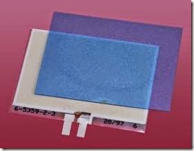
The interior components of a disassembled elec- troluminescent night-light are shown in Figure 26-1. The panel emits a natural pale green glow. A separate blue or green filter passes the glow while blocking other colors of incident light that would otherwise reflect off the panel.
Figure 26-1. The two interior components of an electroluminiscent night-light: the luminescent panel, and a separate translucent filter.
Electroluminescent night-lights were popular in the 1970s and 1980s, often featuring cartoon characters to appeal to children. Figures 26-2 and 26-3 show the same night-light in its daytime off- state and its night-time on-state, respectively.
Figure 26-2. A vintage Panelescent brand night-light, several decades old, in its off-state.
Figure 26-3. The same night-light, with its green radiance visible under conditions of low ambient light.
Advantages of electroluminescent panels include the following:
• Low current consumption. One US manufacturer claims that a single exit sign will use electricity costing less than 20 cents per year, while the annual cost of a night-light will be less than 3 cents per year.
• Long life, up to 50,000 hours.
• Self-regulating; no control circuitry required.
• Omnidirectional light output.
• Very wide operational temperature range, between approximately -60 and +90 de- grees Celsius.
• Can be plugged directly into a wall outlet. Disadvantages include:
• Limited light output.
• Very limited choice of colors.
• Not very efficient, 2 to 6 lumens per watt (al- though the low light output naturally entails low power consumption).
• Gradual reduction in phosphor performance over time.
• High voltage required: 60V to 600V. Ideal for plugging into a wall outlet, but requires a converter when used with battery-powered devices.
Flexible Ribbons
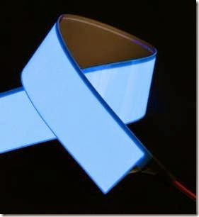
The light-emitting layers inside a night-light are somewhat flexible, and can be made more flexible by reducing their thickness. The result is an electroluminescent ribbon that has some novelty value, and may be used for customizing auto- mobiles. Figure 26-4 shows a ribbon about 1.5” wide and 12” long, designed for 12VDC power applied through an inverter.
Rope Light
A rope light or wire light may resemble a glow- stick. However, a glowstick generates light from chemiluminescence (chemical reactions that re- lease photons), while a rope light uses electricity.
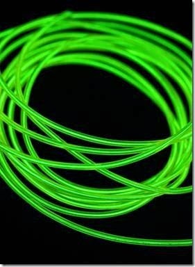
Figure 26-5 shows a rope light powered by two AA batteries connected through an inverter.
At the center of the rope light is a conductor that serves as one electrode. It is coated in phosphors, and the layer of phosphors is protected by a transparent sheath. One or more thin wires is wrapped around the sheath in a spiral, with large gaps between one turn and the next. These wires serve as the second electrode. The wires are en- closed in transparent insulation that forms an outer sheath.
Figure 26-4. A 12” length of electroluminescent ribbon.
When AC is applied between the electrodes, the layer of phosphors emits light that radiates out in the gaps between the thin wires. The color of the light can be modified by using tinted outer insulation.
OLED
An OLED uses two thin, flat electrodes, some- what like a thick-phosphor electroluminescent panel, except that it contains more layers and is capable of generating more light. The layers in an OLED are “organic” in that they consist of chemically organic molecules containing carbon and hydrogen atoms and generally do not contain heavy metals.
While an LCD video monitor or TV screen must have a separate backlight, an OLED generates its own light. This reduces the thickness of the dis- play to a few millimeters and makes it potentially more efficient.
The semiconductor layers are subdivided into pixels, each functioning as a light-emitting di- ode, while additional layers carry a matrix of conductors for pixel addressing. In an AMOLED, the conductors form an active matrix, while in a PMOLED, they form a passive matrix.
Figure 26-5. A length of glowing rope light, also known as a light wire.
In an active matrix, each pixel is backed with a thin-film transistor to store its state while the energizing voltage transitions. This is often de- scribed as a TFT display; but the term is interchangable with “active matrix.”
In a passive matrix, each pair of conductors simply supplies current to a pixel. This is cheaper and easier to fabricate but is less responsive.
The terms “active matrix” and “passive matrix” have the same meaning as when used to de- scribe a liquid-crystal display.
Monochrome OLED display modules with dot- matrix characters are currently available from China for just a few dollars. Although they appear superficially similar to LCD modules, they generate pure white-on-black characters.
Small full-color OLED screens are used in smart- phones and on camera backs, but at the time of writing, large OLED screens are not a mature technology, partly because of production costs. A great variety of chemicals and layer configurations have been tried, and the application of pixels to a substrate has been attempted with vacuum deposition through a shadow mask and with a system similar to inkjet printing. Pixels that emit red, green, and blue light have also been used. Filtered pixels have been used. One dominant process has not yet emerged.
Longevity and brightness have been problems. Where red, green, and blue diodes have been
used, the different colors deteriorate at different rates. While the human eye tolerates an overall reduction in brightness, it does not tolerate a slight color shift caused by blue pixels, for in- stance, losing brightness more rapidly than red pixels.
Because OLED screens promise to be thinner, lighter, and brighter, and may eliminate the need for a fragile glass substrate, there is a strong incentive to develop this technology, which seems likely to gain dominance in the future.
OLED panels may also become a source of diffuse, shadowless room lighting or office lighting when practical problems have been solved and costs have fallen significantly.


