audio indicator
An audio indicator is defined here as a noise-creation device that generates a simple tone or series of tones. Unlike a transducer, which requires an external source of AC to determine its audio frequency, an indicator contains its own electronics and requires only a DC power supply. Either of these components is often described as a beeper or buzzer.
While piezoelectric alerts formerly used crystals, only the more modern piezoelectric type that uses a ceramic wafer will be considered here.
What It Does
When DC power is applied to an audio indicator, in its simplest form it creates a continuous or intermittent tone of a fixed frequency. This is called an alert.
Audio alerts are used in microwave ovens, washer/dryers, automobiles, gasoline pumps, security devices, toys, phones, and many other consumer products. They are often applied with touch pads, to provide audio confirmation that a tactile switch has been pressed.
A few indicators are programmed to create a two-tone sound, or multiple-tone sequences.
See Figure 27-1 in the previous entry for an assortment of schematic symbols that may be used to represent either an alert or a transducer.
How It Works
from around 0.5” to 1.5” in diameter. The enclosure is sealed at the bottom but has a small hole at the top, so that sound can emerge from the upper side of the diaphragm without being partially cancelled by sound of opposite phase that is emitted from the underside of the diaphragm. The enclosure also contains electronics to generate one or more audio tones, and amplifies the sound by resonating with it, in the same way that the body of a guitar or violin amplifies a note being played on the strings.
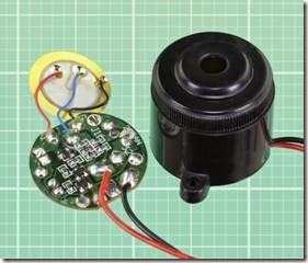
A PUI XL453 piezoelectric audio indicator is pictured in Figure 28-1, fully assembled on the right, and with its circuit board and diaphragm re- moved on the left. This indicator creates a pulsed tone at 3.5kHz with a sound pressure of 96dB. It draws 6mA at 12VDC and measures approximately 1” in diameter.
For more information about the measurement of sound frequency and pressure, see “Frequency A circular diaphragm is glued at its edges inside a cylindrical plastic enclosure, usually measuring Range” on page 251 and “Sound Pressure” on page 251 in the previous entry.
Figure 28-1. A typical piezoelectric audio indicator.
Externally, an audio indicator may be indistinguishable from a transducer. However, internally, an indicator is almost always a piezoelectric de- vice, in which a ceramic wafer is mounted on a thin brass diaphragm. The term piezo is derived from the Greek piezein, which means to squeeze or press.
A transducer (described in the previous entry) is a piezoelectric or electromagnetic alert that does not usually contain its own circuitry and must be driven by an external source of AC, which establishes the audio frequency.
The distinction between an indicator and a transducer is often unclear in parts catalogs, where all alerts may be identified as buzzers, even though they mostly beep rather than buzz.
Audio Frequency
For a discussion of audio frequency, see “Fre- quency Range” on page 251 in the previous en- try.
History
Probably the earliest form of electrically activated alert was the door bell, in which a 6VDC battery-powered solenoid pulled a springloaded lever terminating in a small hammer. The hammer struck the bell, but the motion of the lever also opened a pair of contacts, cutting off power to the solenoid. The lever sprang back to its rest position, which closed the contacts and repeated the cycle so long as power was supplied through an external pushbutton.
Subsequent systems used a small loudspeaker powered by AC house current through a step- down transformer. This created a buzzing sound and may have been the origin of the term “buzzer.”
Small components that made a beeping sound only became common when digital equipment required a simple, cheap way to confirm user in- put or attract attention to the status of a device.
Variants
Sound Patterns
Because an audio indicator contains its own electronics, the manufacturer has the freedom to create various patterns of sound output.
The default is a steady tone. Other common variants include an intermittent tone and a dual tone that fluctuates rapidly between two frequencies. This is sometimes referred to as a siren. A few variants can generate an output pat- tern consisting of several tones in sequence, or effects such as warbling or whooping sounds, which are used mainly in alarm systems.
Formats
Some audio indicators are available in surface- mount format, measuring 1/2” square or less. Be- cause the resonant frequency is related to the size of the component, surface-mount alerts usu- ally make a high-pitched beep.
Panel-mount and board-mount formats range from about 1/2” to 1.5” in diameter. A small audio alert designed to be mounted on a circuit board is shown in Figure 28-2, with its top removed on the right to expose the brass diaphragm glued around the edges. The same component is shown with its plastic enclosure removed completely in Figure 28-3.
Figure 28-2. An audio indicator approximately 0.5” in diameter, partially disassembled on the right, revealing its brass diaphragm.
Figure 28-3. The same indicator from the previous photograph, with its enclosure completely removed.
Values
For an explanation and discussion of sound pressure and its measurement in decibels, see “Sound Pressure” on page 251 in the previous entry.
Audio indicators generally have a sound pressure rating in dBSPL ranging between 65dBSPL to 95dBSPL, with just a few products that make more or less noise. At 120dB and above, most products are packaged as alarm sirens ready for installation, often with a small horn attached. Their power consumption can be 200mA or
more, and they are many times the price of a simple indicator designed for circuit-board mounting.
Voltage
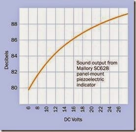
An audio indicator containing its own electronics will almost always be rated somewhere in the range from 5VDC to 24VDC. Sirens intended for use with burglar alarms are often designed for 12VDC or 24VDC, as these are popular values for security systems with battery backup. However, in addition to a rated voltage, a datasheet may specify a wide range of acceptable operating voltages. For example, an indicator with a rated voltage of 12VDC may have an operating voltage of 3VDC to 24VDC. Naturally, the sound intensity will vary with the voltage, but not as much as one might assume. The graph at Figure 28-4 shows that the sound output from an alarm, measured in decibels, increases by only 8dB when voltage increases by almost a factor of five. Of course, the decibel scale is not linear, but human perception of sound is not linear, either.
Figure 28-4. Variation of sound output relative to voltage, in a commonly used piezoelectric indicator.
Current
Typical piezoelectric indicators use less than 10mA (often as little as 5mA) and generate negligible heat.
Frequency
The most common frequencies for indicators range between 3kHz and 3.5kHz. Piezoelectric elements are inefficient for generating sounds below 1kHz.
Duty Cycle
Piezoelectric alerts generate very little heat and can be run on a 100% duty cycle.
If an alert will be pulsed briefly, the minimum pulse time is 50ms. A shorter duration will merely generate a clicking sound.
How to Use It
Appropriate Sound Intensity
An indicator should be chosen with reference to the environment in which it will be used. To be easily heard, it should be at least 10 dB louder than the ambient background noise.
Volume Control
Sound intensity can be reduced by reducing the voltage. Because an indicator does not consume much current, a trimmer can serve as a volume control. Alternatively, a rotary switch with a set of fixed-value resistors can select preset sound values.
However, in many indicators, variations in volt- age may have relatively little effect on sound output, as shown in Figure 28-4.
Wiring
An indicator requires DC voltage. Because the indicator contains a transistor, polarity of the power supply is important. If the indicator has leads attached, the one intended for connection to the positive side of the power supply will be red. If it has pins, the longer pin will be for the positive connection.
What Can Go Wrong
The potential problems in an indicator are the same as those for a transducer. See “What Can Go Wrong” on page 254 in the previous entry.


